Transcription
swagelok.comAn Installer’sPocket Guide for SwagelokTube Fittings
Table of ContentsIntermix/Interchange. . . . . . . . . . . . . . . . . . . . 10Metric Swagelok Tube Fittings . . . . . . . . . . . 10Installation Instructions Safety Precautions. . . . . . . . . . . . . . . . . . . . . . . . . . 11 Up to 1 in./25 mm Swagelok Tube Fittings . . . . . . . 12 Over 1 in./25 mm Swagelok Tube Fittings. . . . . . . . 13 Gaugeability. . . . . . . . . . . . . . . . . . . . . . . . . . . . . . . . 13 Reassembly. . . . . . . . . . . . . . . . . . . . . . . . . . . . . . . . 14 O-Seal Male Connectors. . . . . . . . . . . . . . . . . . . . . . 15 Caps and Plugs. . . . . . . . . . . . . . . . . . . . . . . . . . . . . 15 Pipe Thread Fittings. . . . . . . . . . . . . . . . . . . . . . . . . 15 Port Connectors . . . . . . . . . . . . . . . . . . . . . . . . . . . . 16 Positionable Elbows and Tees . . . . . . . . . . . . . . . . . 18 Tube Adapters. . . . . . . . . . . . . . . . . . . . . . . . . . . . . . 19 Weld Fittings . . . . . . . . . . . . . . . . . . . . . . . . . . . . . . . 20 Depth Marking Tool. . . . . . . . . . . . . . . . . . . . . . . . . . 20 Preswaging Tool. . . . . . . . . . . . . . . . . . . . . . . . . . . . . 21 Tools Required for Gaugeable PreswagingTool Instructions . . . . . . . . . . . . . . . . . . . . . . . . . . . . 22 Gaugeable Preswaging Tool Instructions. . . . . . . . . 23 Gaugeable Preswaging Tool, TubeFitting Installation . . . . . . . . . . . . . . . . . . . . . . . . . . . 24 Gaugeability. . . . . . . . . . . . . . . . . . . . . . . . . . . . . . . . 25Hydraulic Swaging Units Multihead (MHSU). . . . . . . . . . . . . . . . . . . . . . . . . . . 26 Air-Actuated (AHSU) . . . . . . . . . . . . . . . . . . . . . . . . . 27
Tubing Installation . . . . . . . . . . . . . . . . . . . . . . . . . . . . . . . . . 28 Selection . . . . . . . . . . . . . . . . . . . . . . . . . . . . . . . . . . 29 Gas Service. . . . . . . . . . . . . . . . . . . . . . . . . . . . . . 29 Fractional Carbon Steel Tubing . . . . . . . . . . . . . . 30 Metric Carbon Steel Tubing. . . . . . . . . . . . . . . . . 32 Fractional Stainless Steel Seamless Tubing. . . . 34 Metric Stainless Steel Seamless Tubing. . . . . . . 36 Fractional Copper Tubing. . . . . . . . . . . . . . . . . . . 38Ordering Information. . . . . . . . . . . . . . . . 39Straight FittingsUnions Union. . . . . . . . . . . . . . . . . . . . . . . . . . 40 Reducing Union. . . . . . . . . . . . . . . . . 42 Bulkhead Union . . . . . . . . . . . . . . . . . 44 Bulkhead Reducing Union. . . . . . . . . 44Male Connectors NPT. . . . . . . . . . . . . . . . . . . . . . . . . . . 45 ISO/BSP Tapered Thread (RT). . . . . 47 ISO/BSP Parallel Thread (RS). . . . . . 49 ISO/BSP Parallel Thread (RP). . . . . . 51 Bulkhead NPT . . . . . . . . . . . . . . . . . . 53 SAE/MS Straight Thread (ST). . . . . . 54 O-Seal (SAE/MS Straight Thread). . . 55 O-Seal (NPT) . . . . . . . . . . . . . . . . . . . 55 AN Fitting. . . . . . . . . . . . . . . . . . . . . . 56 AN Bulkhead Fitting. . . . . . . . . . . . . . 56 10-32 Thread . . . . . . . . . . . . . . . . . . . 57 M5 0.8 Thread . . . . . . . . . . . . . . . . 57 Metric Thread (RS). . . . . . . . . . . . . . . 57Weld Connectors Tube Socket Weld . . . . . . . . . . . . . . 58 Male Pipe Weld . . . . . . . . . . . . . . . . 58
Straight FittingsFemale Connectors NPT. . . . . . . . . . . . . . . . . . . . . . . . . . . 60 ISO/BSP Tapered Thread (RT). . . . . 62 ISO/BSP Parallel Thread (RJ) . . . . . . 63 ISO/BSP Parallel Thread (RP). . . . . . 63 ISO/BSP Parallel Thread(RG, Gauge) . . . . . . . . . . . . . . . . . . . . 64 Bulkhead NPT . . . . . . . . . . . . . . . . . . 65Reducers Reducer . . . . . . . . . . . . . . . . . . . . . . . 66 Long Reducer. . . . . . . . . . . . . . . . . . . 69 Bulkhead Reducer. . . . . . . . . . . . . . . 69Port Connectors Port Connector. . . . . . . . . . . . . . . . . . 70 Reducing Port Connector. . . . . . . . . 71Caps and Plugs Cap. . . . . . . . . . . . . . . . . . . . . . . . . . . 72 Plug. . . . . . . . . . . . . . . . . . . . . . . . . . . 73 Vent Protectors. . . . . . . . . . . . . . . . . . 7490 ElbowsUnions Union. . . . . . . . . . . . . . . . . . . . . . . . . . 75Male NPT. . . . . . . . . . . . . . . . . . . . . . . . . . . 76 ISO/BSP Tapered Thread (RT). . . . . 78 Reducing. . . . . . . . . . . . . . . . . . . . . . 80 Positionable, SAE/MSStraight Thread (ST). . . . . . . . . . . . . . 80 Positionable, ISO/BSPParallel Thread (PR). . . . . . . . . . . . . . 81Weld Tube Socket Weld . . . . . . . . . . . . . . . 82 Male Pipe Weld . . . . . . . . . . . . . . . . . 82Female NPT. . . . . . . . . . . . . . . . . . . . . . . . . . . 83
45 ElbowsMale NPT. . . . . . . . . . . . . . . . . . . . . . . . . . . 84 Positionable, SAE/MSStraight Thread (ST). . . . . . . . . . . . . . 84TeesUnions Union. . . . . . . . . . . . . . . . . . . . . . . . . . 85 Reducing Union. . . . . . . . . . . . . . . . . 86Male Branch, NPT (TTM) . . . . . . . . . . . . . . 88 Run, NPT (TMT). . . . . . . . . . . . . . . . . 89 Positionable Branch, SAE/MSStraight Thread (TTS). . . . . . . . . . . . . 90 Positionable Run, SAE/MSStraight Thread (TST). . . . . . . . . . . . . 90 Positionable Branch, ISO/BSPParallel Thread (TTR). . . . . . . . . . . . . 91 Positionable Run, ISO/BSPParallel Thread (TRT). . . . . . . . . . . . . 92Female Run, NPT (TFT). . . . . . . . . . . . . . . . . . 93 Branch, NPT (TTF). . . . . . . . . . . . . . 94 Cross, Union. . . . . . . . . . . . . . . . . . . . 95 Sanitary Flange Fittings. . . . . . . . . . . 96
Tube AdaptersMale NPT. . . . . . . . . . . . . . . . . . . . . . . . . . 97 ISO/BSP Tapered Thread (RT). . . . 98 ISO/BSP Parallel Thread (RS). . . . . 99 ISO/BSP Parallel Thread (RP). . . . 100 SAE/MS Straight Thread (ST). . . . 100 O-Seal (SAE/MSStraight Thread). . . . . . . . . . . . . . . 101 AN Thread. . . . . . . . . . . . . . . . . . . . 101 Pipe Weld. . . . . . . . . . . . . . . . . . . .101Female NPT. . . . . . . . . . . . . . . . . . . . . . . . . 102 ISO/BSP Tapered Thread (RT). . . 103 ISO/BSP Parallel Thread (RP). . . . 103 ISO/BSP Parallel Thread(RG, Gauge) . . . . . . . . . . . . . . . . . . 104 ISO/BSP Parallel Thread (RJ) . . . . 105 AN Thread. . . . . . . . . . . . . . . . . . . . 105Part Numbering Tube Fitting Part Numbers. . . . . . 106 Tube Adapter Part Numbers . . . . . 109
Replacement PartsNuts Female . . . . . . . . . . . . . . . . . . . . . . . 111 Knurled Female . . . . . . . . . . . . . . . . 112 Male . . . . . . . . . . . . . . . . . . . . . . . . 112Ferrules Front. . . . . . . . . . . . . . . . . . . . . . . . 113 Back. . . . . . . . . . . . . . . . . . . . . . . . 114 Nut-Ferrule Sets, Packages. . . . . . 115 Ferrule Sets, Ferrule-Paks . . . . . 116ISO/BSP Parallel Gaskets Steel and Stainless Steel(RS Fitting) . . . . . . . . . . . . . . . . . . . 117 Copper (RP and RS Fitting). . . . . . 118 Copper and Nickel(RG, Gauge Fitting). . . . . . . . . . . . . 118 PTFE (RJ Fitting). . . . . . . . . . . . . . . 118O-Rings Buna N (O-SealStraight Threads). . . . . . . . . . . . . . 119 Buna N (O-Seal Pipe Threads) . . . 119 Fluorocarbon FKM(Positionable Fittings,ISO/BSP Parallel Threads). . . . . . . 120 Fluorocarbon FKM(SAE/MS Straight Threads). . . . . . 120Tools and Accessories Bulkhead Retainers. . . . . . . . . . . . 121 Gap Inspection Gauges. . . . . . . . . 122 Depth Marking Tools. . . . . . . . . . . 124 Preswaging Tools. . . . . . . . . . . . . . 125 Inserts for SoftPlastic Tubing. . . . . . . . . . . . . . . . . 126
About SwagelokSwagelok is a leading developer and provider offluid system products, assemblies, and servicesfor the oil and gas, chemical and petrochemical,semiconductor, transportation, and powerindustries. With millions of our products in usearound the world and a growing offering ofservices, Swagelok has long been synonymouswith exceptional quality and reliability.Our expertise in materials science and productdesign, combined with an extensive global salesand service network, enables us to be a highlyvalued resource for our customers, even in themost demanding applications, for experience,insight, and support. We are committed tofostering a culture that promotes our core valuesof innovation, continuous improvement, respect,quality, customer focus, and integrity.We are pleased to provide this global edition ofthe An Installer’s Pocket Guide for Swagelok TubeFittings. This is up to date at the time of printing,with its revision number shown on the back page.Subsequent revisions will supersede the printedversion and will be posted on the Swagelok websiteand in the Swagelok electronic Desktop TechnicalReference (eDTR) tool.Visit swagelok.com to locate your Swagelokrepresentative and obtain information on features,technical information and product references,and the variety of services available only throughauthorized Swagelok sales and service centers.Markets ServedOil and gas; chemical/petrochemical;semiconductor; transportation; power; food,beverage, and dairy; biopharmaceutical; pulpand paper; analytical instrumentation; processinstrumentation
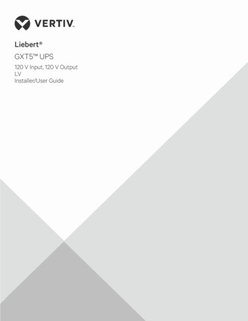
InstallationIntermix/Interchange with OtherManufacturers’ ComponentsElbows and TeesStraight FittingsThis practice can be dangerous. Leak-tight sealsthat will withstand high pressure, vibration, vacuum,and temperature changes depend on closetolerances and consistent, exacting quality control inconjunction with good design principles. The criticalinteraction of precision parts is essential for reliabilityand safety.Components of other manufacturers may look likeSwagelok tube fitting components—but they cannotbe manufactured in accordance with Swagelokengineering standards, nor do they benefit frominnovations in design and manufacture defined bymore than 36 active Swagelok tube fitting patentsissued since 1989.Metric Swagelok Tube FittingsMetric tube fittings have a stepped shoulder on thebody hex.Swagelokfractionaltube stubAdaptersSwagelokmetrictube endStepped identificationshouldersNo shoulderPartsSwagelokmetric tubeendsAccessoriesStepped identificationshouldersShaped fittings, such as elbows, crosses, and tees,are stamped MM for metric tubing and have no stepon the forging.10
Installation InstructionsInstallationSwagelok tube fittings 1 in./25 mm and smaller canbe installed quickly, easily, and reliably with simplehand tools.Over 1 in./25 mm sizes require use of a hydraulicswaging unit to swage the ferrules onto the tubing.Safety Precautions Do not bleed system by loosening fitting nut orStraight Fittingsfitting plug. Do not assemble and tighten fittings whensystem is pressurized. Make sure that the tubing rests firmly onElbows and Teesthe shoulder of the tube fitting body beforetightening the nut. Use the correct Swagelok gap inspectiongauge to ensure sufficient pull-up upon initialinstallation. Always use proper thread sealants on taperedpipe threads. Do not mix materials or fitting components fromvarious manufacturers—tubing, ferrules, nuts,and fitting bodies. Never turn fitting body. Instead, hold fitting bodyand turn nut. Avoid unnecessary disassembly of unusedfittings. Use only long reducers in female Swagelok endconnections.See the instructions starting on the next page forinstallation of Swagelok tube fittings, O-seal maleconnectors, caps and plugs, port connectors,tube adapters, positionable elbows and tees, weldfittings, depth marking tool, and preswaging tool.AdaptersPartsAccessories11
Swagelok Tube FittingsInstallationUp to 1 in./25 mmStraight FittingsSafe practices and proper installation are imperativeto the performance of the Swagelok tube fitting,especially in critical applications.For 5/8, 3/4, 7/8 and 1 in.; 16, 18, 20, 22 and 25 mmtube fittings, in all materials except for aluminum andbrass, it is a best practice to preswage the ferrulesonto the tube adapter using a Swagelok multiheadhydraulic swaging unit (MHSU) to lower installationtime and increase ease of installation (see MultiheadHydraulic Swaging Unit (MHSU), Setup andOperating Instructions, MS-12-37).AdaptersElbows and TeesFully insert the tube into the fittingand against the shoulder; rotatethe nut finger-tight.High-pressureapplicationsand highsafety-factorsystems:Further tightenthe nut until thetube will not turn by hand or move axially in the fitting.PartsMark the nut at the6 o’clock position.AccessoriesWhile holding thefitting body steady,tighten the nut one andone-quarter turns tothe 9 o’clock position.For 1/16, 1/8, and3/16 in.; 2, 3, and4 mm tube fittings,tighten the nut threequarters turn to the 3 o’clock position.12
Swagelok Tube FittingsInstallationOver 1 in./25 mmStraight Fittings1. Preswage the ferrules onto the tube using aSwagelok multihead hydraulic swaging unit(MHSU).2. Apply the lubricant packaged with the fittinglightly to the body threads and the rear surfaceof the back ferrule.3. Insert the tube with preswaged ferrules into thefitting until the front ferrule seats against thefitting body; rotate the nut finger-tight.4. Mark the nut at the 6 o’clock position.5. While holding the fitting body steady, tightenthe nut one-half turn to the 12 o’clock position.Gaugeability PartsIf the gauge will not enterthe gap, the fitting issufficiently tightened.AdaptersOn initial installation, the Swagelok gapinspection gauge assures the installer orinspector that a fitting has been sufficientlytightened.Position the Swagelok gap inspection gaugenext to the gap between the nut and body.Elbows and TeesUse the Swagelok MHSU gap inspection gauge toensure that the fitting has been tightened sufficiently.If the gauge will enter thegap, additional tighteningis required.AccessoriesWarningAlways depressurize a system beforeadjusting the tightness of a tube fittingconnection.13
Swagelok Tube FittingsInstallationReassembly—All SizesYou may disassemble and reassemble Swageloktube fittings many times. Always depressurize the system beforedisassembling a Swagelok tube fitting.Elbows and TeesStraight FittingsPrior to disassembly, mark thetube at the back of the nut;mark a line along the nutand fitting body flats.Use these marks toensure that you returnthe nut to the previouslypulled-up position.AdaptersInsert the tube with preswagedferrules into the fitting untilthe front ferrule seatsagainst the fittingbody.Over 1 in./25 mmsizes: If needed,reapply lubricantlightly to the bodythreads and the rear surface of the back ferrule.AccessoriesPartsWhile holding the fittingbody steady, rotate thenut with a wrenchto the previouslypulled-up position,as indicated by themarks on the tubeand flats. At thispoint, you will feel asignificant increasein resistance. Tighten the nut slightly. 14CautionDo not use the Swagelok gap inspectiongauge with reassembled fittings.
O-Seal Male ConnectorsInstallation1. Turn the O-seal connector into the female enduntil it is finger-tight.2. Tighten the O-seal connector until it makesmetal-to-metal contact with the face of thefemale end.3. Tighten slightly with a wrench.Straight FittingsO-rings are coated with a thin film of silicone-basedlubricant. Removal of factory-applied lubricantsmay alter performance.Caps and PlugsCapsElbows and TeesSee Swagelok tube fitting installationand reassembly, page 15 and 14Plugs AdaptersWhile holding fitting body steady,tighten the plug one-quarter turn fromthe finger-tight position.For 1/16, 1/8, and 3/16 in.; 2, 3, and 4 mm tube fittings,tighten the plug one-eighth turn.For over 1 in. and over 25 mm tube fittings, tightenthe plug one-quarter turn.Do not use the Swagelok gap inspectiongauge with plug assemblies.ReassemblyPartsYou may disassemble and reassemble Swagelokplugs many times. Make subsequent connectionsby slightly tightening with a wrench after snuggingthe nut by hand.Pipe Thread FittingsAccessoriesA thread sealant should always be used whenassembling tapered threads. SWAK anaerobicpipe thread sealant, PTFE-Free pipe thread sealant,and Swagelok PTFE Tape are available. For moreinformation, see the Swagelok Leak Detectors,Lubricants, and Sealants catalog, MS-01-91.15
Port ConnectorsInstallationConnect the machined ferrule end beforeconnecting the tube adapter end.Machined Ferrule EndStraight FittingsSWAGELOKSWAGELOK1. Remove the nut and ferrules from the Swagelokend connection. Discard the ferrules.DiscardSWAGELOKSWAGELOKElbows and Tees2. Slip the nut over the machined ferrule end of theport connector. Over 1 in./25mm sizes:The nut ispreassembledon the port1 in./25 mmOver 1 in./25 mmand underconnector.3. Insert the portconnectorinto the endconnectionand fingertighten the nut.4. While holdingfitting bodysteady, tightenthe nut onequarter turn. For 1/16, 1/8,and 3/16 in.; 2, 3,and 4 mm tubefittings, tightenthe nut oneeighth turn.SWAGELOKPartsAdaptersSWAGELOKAccessories 16Do not usethe Swagelok gap inspection gauge withmachined ferrule ends.
Port ConnectorsInstallationReassemblyYou may disassemble and reassemble Swagelokport connectors many times. Make subsequentconnections by slightly tightening with a wrenchafter snugging the nut by hand.KOLEGAWSTube Adapter EndKOLEGAWSStraight Fittings5. Insert the tube adapter untilit rests firmly on the shoulderof the Swagelok tube fittingbody. Finger-tighten the nut. Over 1 in./25 mm sizes: Remove and discardthe nut and ferrules from the end connection,then insert the tube adapter.6. Mark thenut at the6 o’clock12position.While holding9fitting body3steady,6tighten thenut one andone-quarterturns to the9 o’clockposition. For 1/16, 1/8, and 3/16 in.; 2, 3, and 4 mm tubefittings, tighten the nut three-quarters turn tothe 3 o’clock position. For preswaged over 1 in./25 mm and over tubefittings, tighten the nut one-half turn to the12 o’clock position.Elbows and TeesAdaptersParts Do not use the Swagelok gap inspectiongauge with preswaged tube adapterconnections over 1 in./25 mm.AccessoriesReassemblySee Swagelok tube fitting reassembly, page 14.17
Positionable Elbows and TeesAccessoriesPartsAdaptersElbows and TeesStraight FittingsInstallation1. Turn the positionable endinto the female fitting untilthe metal backup washercontacts the face of theLock nutfitting.2. Turn the positionable endBackupwasherout of the female fitting(not more than one turn)until the Swagelok tube fitting end is positionedproperly.3. While holding fitting body steady, tighten thelock nut until the metal backup washer contactsthe face of the fitting.18
Tube AdaptersInstallationUp to 1 in./25 mmStraight FittingsSafe practices and proper installation areimperative to the performance of the Swageloktube fitting, especially in critical applications.For 5/8, 3/4, 7/8 and 1 in.; 16, 18, 20, 22 and 25 mmtube fittings, in all materials except for aluminumand brass, it is a best practice to preswage theferrules onto the tube adapter using a Swagelokmultihead hydraulic swaging unit (MHSU) to lowerinstallation time and increase ease of installation(see Multihead Hydraulic Swaging Unit (MHSU),Setup and Operating Instructions, MS-12-37).Female pipe1. Install the endport on existingopposite the tubeequipmentadapter end.Elbows and TeesAdapters2. Insert the tube adapter into the Swagelok tubefitting. Make sure that thetube adapter rests firmlyon the shoulder of thetube fitting body and thatthe nut is finger-tight.3. Mark the nut at the 6 o’clock position.4. While holding fitting body steady, tighten thenut one and one-quarter turns to the 9 o’clockposition. For 1/16, 1/8, and 3/16 in.; 2, 3, and 4 mm tubefittings, tighten the nut three-quarters turn tothe 3 o’clock position.PartsOver 1 in./25 mmSwagelok tube adapters over 1 in./25 mm arefurnished with nuts and preswaged ferrules.To assemble, follow steps 2 through 5 of theSwagelok tube fittings over 1 in./25 mm assemblyinstructions, page 13.Accessories Do not use the Swagelok gap inspectiongauge with preswaged tube adapterconnections over 1 in./25 mm.19
Tube AdaptersInstallationReassemblySee Swagelok tube fitting reassembly, page 14.Weld FittingsStraight FittingsWelding Precautions for Swagelok TubeFittings with Weld End ConnectionsElbows and Tees1. Remove the nut and ferrules.2. Turn a Swagelok tube fitting plug or anothernut onto the fitting so that it is finger-tight. Thisprotects the threads and sealing components.3. Provide a suitable heat sink to dissipate the heat.4. Tack weld at four positions 90 apart to holdthe fitting in place and to ensure alignment andconcentricity of the components.5. Complete the weld.6. Remove the plug or nut and replace the nut andferrules.Adapters CautionWhen welding carbon steel fittings, the heatoften removes the protective oil from thethreads. It is important to apply anotherlubricant, such as Goop thread lubricant.Depth Marking ToolAccessoriesParts1. Insert cleanly cut, fully deburred tubeinto the depth marking tool (DMT)until the tube is against the shoulderof the tool. Using a pen or pencil,mark the tube at the top of the DMT.2. Remove the tube from the DMT andinsert it into the Swagelok fitting untilit is against the shoulder of the fittingbody. Rotate the nut finger-tight. Ifany portion of the mark on the tubecan be seen above the fitting nut, thetube is not fully inserted into the fitting.3. While holding the fitting body steady, followSwagelok tube fitting installation instructions,page 12.20
Preswaging ToolStraight FittingsElbows and TeesAdaptersParts Installation1. Install the Swagelok nut and ferrules onto thepreswaging tool.2. Insert the tube into the preswaging tool.3. Make sure that the tube rests firmly on theshoulder of the preswaging tool body and thatthe nut is finger-tight.4. Mark the nut at the 6 o’clock position.5. While holding the preswaging tool steady,tighten the nut one and one-quarter turns to the9 o’clock position. For 1/16, 1/8, and3/16 in.; 2, 3, and4 mm tube fittings,tighten the nut onlythree-quarters turnto the 3 o’clock position.6. Loosen the nut.7. Remove the tube with preswaged ferrules fromthe preswagingtool. If the tubesticks in thepreswaging tool,remove the tube by gently rocking it back andforth. Do not turn the tube.8. Insert the tube with preswaged ferrules into thefitting body until the front ferrule seats againstthe fitting body.9. While holding the fitting body steady, rotate thenut with a wrench to the previously pulled-upposition; at this point, you will feel a significantincrease in resistance.10. Tighten the nutslightly.AccessoriesDo not use the Swagelok gap inspectiongauge with fittings that were assembledusing the preswaging tool.21
InstallationTools Required for GaugeablePreswaging Tool InstructionsStraight Fittings1. Gaugeable preswage tool. Gaugeable tools are available in sizes 1/4, 3/8,1/2, 5/8 in., and 6, 8, 10, 12, 16 mm.Elbows and Tees2. Body wrench and nut wrench.Adapters3. Standard gap gauge for standard assembly.AccessoriesParts4. Severe-service gap gauge for severe serviceassembly.22
InstallationGaugeable Preswaging ToolInstructions1. Install the Swagelok nut and ferrules onto thepreswaging tool.Straight Fittings2. Insert the tube into the preswaging tool until itrests firmly on the shoulder of the tool; rotatethe nut finger-tight.Elbows and Tees3. While holding the preswaging tool steady,tighten the nut with a wrench until it stopsagainst the collar.Adapters4. Loosen the nut and remove the tube withpreswaged ferrules from the preswaging tool.If the tube sticks, gently rock it back and forth.Do not turn the tube.PartsAccessories23
InstallationGaugeable Preswaging Tool, TubeFitting InstallationStraight Fittings1. Insert the tube with preswaged ferrules into thefitting until the front ferrule seats against thefitting body; rotate the nut finger-tight.Elbows and Tees2. Mark the nut at the 6 o’clock position.AccessoriesPartsAdapters3. While holding the fitting body steady, tightenthe nut one‑half turn to the 12 o’clock position.Note: I f assembling fittings for high-pressureapplications or high safety-factorsystems, tighten one hex flat further thanone-half turn.24
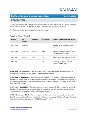
GaugeabilityInstallationOn initial installation, the Swagelok gap inspectiongauge assures the installer or inspector that a fittinghas been sufficiently tightened.If the nut was tightened additionally during installation (step 3 on previous page), use Fig. 1 for gauging, otherwise use Fig. 2.Straight FittingsPosition the Swagelok gap inspection gauge next tothe gap between the nut and body. If the gauge will not enter the gap, the fitting is sufficiently tightened. I f the gauge will enter the gap, additional tightening is required.Fig. 1Elbows and TeesAdaptersFig. 2PartsAccessories25
Hydraulic Swaging UnitsStraight FittingsInstallationSwagelok hydraulic swaging units preswageSwagelok ferrules onto tubing prior to assembly andprovide Swagelok tube fitting connections that are100 % gaugeable upon initial installation. Multiheadhydraulic and air-actuated hydraulic swaging units: Place no initial strain on fitting body threads or onbody seal surfaces Are available with interchangeable fractional andmetric tooling Fit neatly in a rugged plastic carrying case Reduce assembly and installation time andoperator errorElbows and TeesMultihead (MHSU)Adapters Is available in two unit sizes, with tooling for: Parts 1/2 to 1 in. and 12 to 25 mm tubing and tubeadapters 1 to 2 in. and 25 to 50 mm tubingMust be used to install 1 1/4, 1 1/2, and 2 in. and28, 30, 32, 38, and 50 mm Swagelok tube fittingsIs standard with a tube marking feature to indicatewhen tube is properly bottomed in the unitIs available with a support base (as shown)Is available with hydraulic hose; support base isrequiredAccessoriesThe MHSU cannot be used for alloy 2507 tubing1/2 in. and under or for medium-pressure tubing.For 5/8 and 3/4 in. alloy 2507 tubing, order the1 in./25 mm and over unit and alloy 2507 toolingkit and gap inspection gauges.26
Hydraulic Swaging UnitsInstallationAir-Actuated (AHSU)Straight Fittings Requires only one unit with interchangeabletooling to swage 1/4 to 1/2 in. and 6 to 12 mmSwagelok tube fitting ferrule sizes Requires no threading of nut on or off the toolingElbows and TeesThe AHSU cannot be used for alloy 2507 tubingor for medium-pressure tubing.Additional Information, MHSU and AHSUAdaptersSee the Swagelok Gaugeable Tube Fittings andAdapters catalog, MS-01-140. For instructions, seeMultihead Hydraulic Swaging Unit (MHSU) Setupand Operation Instructions, MS-12-37, and AirActuated Hydraulic Swaging Unit (AHSU) Setup andOperation Instructions, MS-12-38.PartsAccessories27
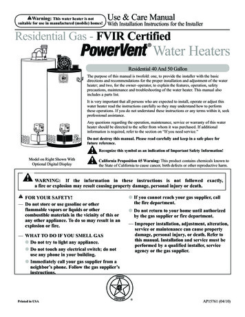
Tubing InstallationStraight FittingsInstallationTubing properly selected and handled, whencombined with the quality of Swagelok fittings, willgive you leak-tight systems. Properly installed onsuch tubing, Swagelok fittings provide reliable serviceunder a wide variety of fluid applications.When installing fittingsTnear tube bends, thereRmust be a sufficientstraight length ofT Tube ODtubing to allow theLL Required straighttube to be bottomedtube length(see table)in the Swagelok fittingR Radius of tubing(see tables below).Elbows and TeesbendFractional, in.AdaptersTTube /812313/815/16141/21 3/16153/41 1/4Accessories1632187/81 5/162011 1/2221 1/4225401 1/22 13/32284623 1/43050325438635080➀ Required straight tube length.28L➀1/165/8PartsMetric, mmTTube OD34
Tubing Selection Elbows and Tees material. For example, stainless steel tubingshould not be used with brass fittings.When tubing and fittings are made of the samematerial, tubing must be fully annealed.Always use an insert with extremely soft orpliable plastic tubing.Extremes of wall thickness should always bechecked against the suggested minimum andmaximum wall thickness limitations.Surface finish is very important to proper sealing.Tubing with any kind of depression, scratch,raised portion, or other surface defect will bedifficult to seal, particularly in gas service.Tubing that is oval and will not easily fit throughfitting nuts, ferrules, and bodies should never beforced into the fitting.Straight Fittings Installation Metal tubing material should be softer than fittingGas ServiceAdaptersGases (air, hydrogen, helium, nitrogen, etc.) have verysmall molecules that can escape through even themost minute leak path. Some surface defects on thetubing can provide such a leak path. As tube outsidediameter (OD) increases, so does the likelihood ofa scratch or other surface defect interfering withproper sealing.The most successful connection for gas servicewill occur if all installation instructions are carefullyfollowed and the heavier wall thicknesses of tubingon the following tables are selected.A heavy-wall tube resists ferrule action more thana thin-wall tube, allowing the ferrules to coin outminor surface imperfections. A thin-wall tube offersless resistance to ferrule action during installation,reducing the chance of coining out surface defects,such as scratches. Within the applicable suggestedallowable working pressure table, select a tube wallthickness whose working pressure is outside of theshaded areas.PartsAccessories29
Fractional Carbon Steel TubingInstallationAllowable working pressures are calculated froman S value of 15 700 psi (108.2 MPa) for ASTM A179tubing at –20 to 100 F (–28 to 37 C), as listed inASME B31.3. For working pressure in accordancewith ASME B31.1, multiply by 0.85.Suggested Ordering InformationAccessoriesPartsAdaptersElbows and TeesStraight FittingsHigh-quality, soft annealed seamless carbonsteel hydraulic tubing, ASTM A179 or equivalent.Hardness not to exceed 72 HRB or 130 HV. Tubingto be free of scratches, suitable for bending andflaring.30
15001Access
www .swagelok .com An Inst