Transcription
by HoneywellTHE GENT ENHANCED POCKETDESIGN & INSTALLATION GUIDE
by HoneywellFIRE DETECTION SYSTEMSThis Pocket Design & Installation booklet provides a simple guide for the provision of a firedetection and alarm system in accordance with the recommendations detailed within theBritish Standard Code of Practice BS5839-1:2002 A2:2008The handbook is designed to act as an aide-memoire and there is no substitute for readingthe full standard, copies of which can be obtained from:British Standards Institute 389 Chiswick High Road, Chiswick, London W4 4ALTel: 020 8996 9001 Web: www.bsi-global.com Email: orders@bsi-global.comContents4 Introduction4 Legal elements444Regulatory Reform Fire Safety Order 2005The Equality Act 2010 (formerly the Disability Discrimination Act 1995)Building Regulations Approved Document Part B and Approved Document Part M4 System DesignOutline responsibilities of the Designer4 Stage 1 Talk to the interested parties to decide on the level of protection orcategory and agree variations4 Stage 2 Detection & alarm zones4 Stage 3 Siting of manual call points4 Stage 4 Selection and siting of sensors4 Reduce the risk of false alarms with the Gent sensor application guide4 Stage 5 Choice and siting of alarm sounders and visual alarms4 Stage 6 Control equipment & power supplies44 Installation & Wiring44444Outline responsibilities of the InstallerTypes of cable and where to use themOther aspects in regard to installation practiceRecommendations for mains power suppliesInspection & testing of wiring4 Commissioning4Outline responsibilities of the Commissioning Engineer4 Identifying additional Variations or ‘snags’4 Cause & Effect Matrix4 Final documentation4 Best Practice Tips1
FIRE DETECTION SYSTEMSIntroductionThis guide, due to its size, provides a basic overview to anyone involved in the design oraction of a fire detection system. It will identify the current legislative requirements as wellas clarify the responsibilities placed on the three key roles involved with the provision of anew system, namely the Designer, Installer and Commissioning Engineer, as well as remindthe End User or Owner/Occupier what part they play in ensuring that the best possiblesystem is supplied to protect life and property from fire.It is important that everyone involved is conversant with the current British StandardCodes of Practice BS5839-1:2002 A2:2008 for general buildings and BS 5839-6:2004 fordwellings including those of multiple occupancy. The Installer should also be conversantwith the British Standard relating to general wiring BS 7671.The guide, which has been prepared by Gent, one of the UK’s largest manufacturers of firedetection systems, is intended to offer practical advice and is not a substitute for any ofthe standards or legislation referred to.Legal elements4Regulatory Reform Fire Safety Order 2005The Equality Act 2010(formerly the Disability Discrimination Act 1995)Building Regulation Approved Document Part B4Building Regulation Approved Document Part M44All these documents in some way affect what is includedin the system. However the Owner/Occupier is ultimatelyresponsible for the level of protection provided.It is recommended that the Owner/Occupier carries outa Fire Risk Assessment to identify the level of protectionrequired i.e. one of the categories detailed within BS58391:2002 A2:2008( L1,L2,L3,L4,L5,M,P1 or P2 )The full responsibilities of the Owner/Occupier are detailedwithin the new Regulatory Reform Fire Safety Order (RRO)that replaced the majority of existing laws within the UK fromOctober 2006.2
by HoneywellSystem DesignAny design should be prepared by a competent individual/organisation, who has consultedall interested parties and created a set of drawings, a specification, a cause & effect or fireplan, a list of Variations and completed a G1 Design certificate, detailed within BS58391:2002 A2:2008.If designs are undertaken without this research being carried out, the fire detection systemis unlikely to comply with the legal requirements. This could result in prosecution of theparties involved, particularly those within the supply chain as well as the Owner/Occupier.WARNING: Anyone who takes on the responsibility for design will do so at their own riskand design liability insurance is advisable.The Designer’s responsibilities:Agree the level of protection or category with Owner/OccupierJustify any Variations and document reasons4 Detail the detection & alarm zones4 Prepare specification and drawings including;4 Siting of manual call points4 Siting of point type heat and smoke detectors4 Siting of beam detectors4 Siting of any other forms of detection4 Specify type of cable for each circuit4 Specify type of system and equipment4 Include detail for on/off site links with other equipment4 Take into account the risk of false alarms – use the Gent ‘pull out’ application guide atthe back of this booklet4 Allow for correct level of sounders and visual alarms4 Prepare a fire plan or cause and effect chart4 Sign a G1 design certificate44Note BS5839-1:2002 A2:2008 recommends that a fire detection system isdesigned by a competent person, who takes responsibility for completing thedesign and signing off a ‘Design certificate’ G1. This should not be confusedwith other certificates relating to Installation G2 and Commissioning G3, that arecompleted by the parties responsible for those parts.Also if the contract allows, it is suggested that the Designer witness tests thecompleted system to ensure the original design is still appropriate – the Designcertificate can then be completed after any amendments are included.3
FIRE DETECTION SYSTEMSDesign Stage 1Talk to the interested parties to decide on the level of protection or categoryand agree VariationsThe importance of pre-design planning cannot be overstated. Many parties are likely tohave an interest in what the fire detection is expected to do. Ultimately it is up to theOwner/Occupier, who is responsible by law, to make the final decision on the level ofprotection provided for a particular building.In most circumstances the Owner/Occupier will appoint a competent Designer to carry outthis work and take liability for the design as a whole.The nominated Designer is expected to consult the following organisations:4 The User or Facilities Manager4 The Building Control Officer4 The Health and Safety Executive4 The Insurer4 The local Fire and Rescue Service4 A specialist fire alarm system supplierIssues to be covered by the Designer should include:44444The Fire Risk Assessment demandsThe requirements necessary to comply with the Regulatory Reform (Fire Safety) Order(RRO) 2005, the Equality Act 2010 (formerly the Disability Discrimination Act 1995) andBuilding Regulations Approved Documents Part B and Part MThe prime purpose of the system (Property or life protection or both)The level of protection suggested by the interested parties.(Category P1 or P2, M or L1 L2 L3 L4 or L5)The list of Variations identified by the interested parties4
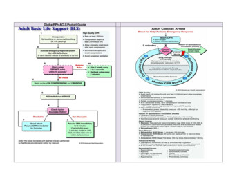
by HoneywellDetermine the SystemCategory or level ofprotectionMSystems designed for Protectionof Property only, fall into twoclassifications P1 or P2.The objective of a Category P1is to provide the earliest possiblewarning of a fire to minimise thetime between ignition and thearrival of the fire fighters.P1 is designed to protect thewhole building whilst P2 isinstalled in defined parts of thebuilding only, which may have anextraordinary high risk or hazard.L5Life protection on the other handwill often depend on the numberof people accessing a particularbuilding and depending on thevariations, the systems canrange from simple Type M to L1categories, these being detailed inthe following diagrams.These diagrams show a typicalbuilding with a number of escaperoutes, side rooms and open planareas used for escape.A Category M system requiresmanual call points on allexits as well as corridorswhere persons are notexpected to walk morethan 30/45m (see designnote 3) to operate one.5L4
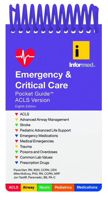
FIRE DETECTION SYSTEMSCategory L5, designed forbuildings that have a particularrisk identified which warrantssome special attention. Forexample if there is an area of highrisk which is considered worthy ofhaving some automatic detectionbut a manual system is alsoneeded, then this will be termedas L5/M.Category L4 provides detectionwithin the escape routes only,whereas L3 not only covers theseareas but all rooms leading ontothe escape route. The reasoningbehind this is to alert people ofthe danger prior to the corridorbecoming “Smoke logged” sopeople can escape safely.L3L2L2 is a further enhancementof protection with all the areascovered by an L3 category aswell as all high risk areas such asboiler rooms etc.L1 provides protection throughoutthe building.L16
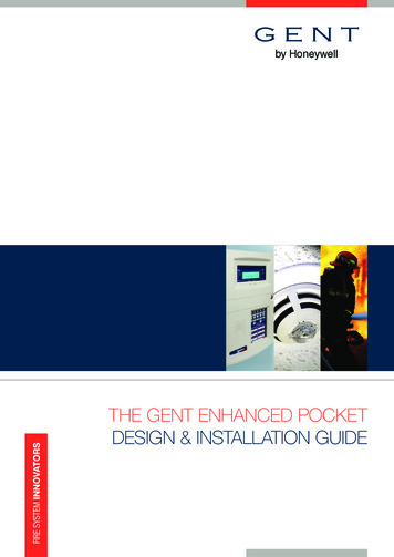
by HoneywellDesign Stage 2Detection and Alarm ZonesGenerally a building is broken down into smaller compartments to enable the fire fightersto locate the fire as quickly as possible.Even if the system is addressable it is still considered beneficial to have a separate ‘at aglance’ indication of the location of the fire.These compartments of a building are called detection zones, which need to comply withthe following criteria.Detection ZonesA detection zone should cover no more than 1 storey, unless total floor area is less than300m2. Voids in the same fire compartment should be included in the same floor zone.The maximum floor area of a zone should not be greater than 2,000m2, except for somelarge open plan areas that incorporate manual call points only, which can be extendedto 10,000m2. The maximum search distance for the fire fighters to see the seat of thefire within a zone should not exceed 60m assuming the route taken is the worst possibleoption. Vertical structures likestairwells, liftwells etc should beconsidered as separate zones4A manual call point within astaircase should be connectedto the zone associated with thatfloor and ideally be mounted onthe accommodation side of thecorridor exit. Automatic sensorson the stairwell remain as partof the stairwell detection zone4ZONE 1ZONE 5ZONE 2ZONE 3ZONE 47
FIRE DETECTION SYSTEMSAlarm zones are only required whenphased or staged evacuation is required. Itis therefore important that care should betaken to ensure only one message is heardat any one time particularly where twoalarm zones are attached.DETECTIONZONE 3DETECTIONZONE 4DETECTIONZONE 5DETECTIONZONE 6DETECTIONZONE 7DETECTIONZONE 8DETECTIONZONE 9DETECTIONZONE 10DETECTIONZONE 11DETECTIONZONE 12ALARMZONE 2DETECTIONZONE 2ALARMZONE 3The only other criteria is that an alarmzone may consist of a number of detectionzones but not visa versa.DETECTIONZONE 1ALARMZONE 4An alarm zone is clearly defined withinthe standard but generally is an areaof the building coinciding with the firecompartment boundaries. There must be aclear break between these alarm zones toensure alert and evacuation messages arenot overheard from adjacent areas.ALARMZONE 1Alarm ZonesDesign Stage 3Siting of Manual Call PointsAll manual call points, whatever the system, should comply to BS EN54-11 single actionType A version only and should be located as follows: On all storey exits and all exits to open air irrespective of whether they are designated4fire exitsNobody should travel more than 45 metres to reach one, except if the exit routes areundefined in which case the direct line distance should not exceed 30 metres4 The above distances to be reduced to 25 and 16 metres respectively, if there are4persons with limited mobility or there is a likelihood of rapid fire development4In all areas with potential high fire risk such as kitchens etc4Where phased evacuation is planned, call points will need to be sited on all exits froma particular zone41.4 metres or – 200mm above the floor4Call points fitted with protective hinged covers for whatever reason should be listed asa variation8
by HoneywellFIREDETECTIONSYSTEMSBSBManual Call PointHSRoute of travel 45m max(defined)HRoute of travel 30m max(undefined)HSBNote: In order to comply with the requirements of Building Regulations ApprovedDocument Part M, which requires electrical switches including manual call points (MCPs)to be mounted at between 1M or – 200mm on wheel chair access routes, these shouldbe listed as a Variation on the certificate as BS requires MCPs to be mounted at 1.4M or – 200mm.Design Stage 4Selection and siting of sensorsFor further advice please refer to clauses 21 & 22 of BS5839-1:2002 A2:2008The objective is to select the correct sensor for the appropriate application, to provide theearliest warning of fire without the risk of a false alarm.It is therefore worth trying to visualise the type of fire that is likely to occur in aparticular room or area and also to familiarise oneself with the application and therisks that could give rise to a false alarm.It should also be remembered that a Vigilon system can incorporate a whole rangeof different sensors using S-Quad multi-sensors. These can be set up for differentapplications and can be switched from ‘state to state’ should particular risks bepresent for short periods of time. This is achieved by an internal programmable timer,key switch or external input source. At the end of this booklet, a pull out section isattached showing a full application guide for all sensors including the latest S-Quadmulti-sensor with a range of selectable ‘states’ for every application and risk.9
FIRE DETECTION SYSTEMSFIREDETECTIONSYSTEMSHeat sensors complying to BS EN54-5Vigilon with the S-Quad heat sensor has a number of pre-programmed ‘states’ that aredetailed within BSEN54-5.Each state has its preferred use as described in the Application guide and incorporatestwo types of heat sensing element. One can be described as fixed temperature whilst theother is known as a rate of rise element. These elements have a broad range of applicationspecific operating states that will respond quickly in the event of fire without riskin
This Pocket Design & Installation booklet provides a simple guide for the provision of a fire detection and alarm system in accordance with the recommendations detailed within the British Standard Code of Practice BS5839-1:2002 A2:2008 The handbook is designed to act as an aide-memoire and there is no substitute for readingFile Size: 1MBPage Count: 50