Transcription
PLC HandbookPractical Guide to Programmable Logic Controllers
2ContentsChapter 1 - What is a PLCp. 3Chapter 2 - History of the PLCp. 5Chapter 3 - How to Choose a Controllerp. 10Chapter 4 - PLC Hardwarep. 14Chapter - 5 PLC Softwarep. 205-15-25-3p. 27p. 29p. 36Understanding Ladder Logic -------------------Basic Instructions in Ladder Logic ------------Ladder Logic in Action ----------------------------Chapter - 6 Practical PLC Topicsp. 486-16-26-36-4p. 49p. 54p. 58p. 61Methods Behind PID Loop Control ------------PLC Communication - Coming of Age---------EtherNet/IP: Implicit vs. Explicit Messaging-Motion Control Explained --------------------------Collection of PLC Application StoriesPLC Handbookp. 66
Chapter 1What is a PLC Programmable Logic Controllers (PLC) are often defined as miniature industrial computers thatcontain hardware and software used to perform control functions. More specifically, a PLC would be usedfor the automation of industrial electromechanical processes, such as control of machinery on factoryassembly lines, amusement rides, or food processing. They are designed for multiple arrangements ofdigital and analog inputs and outputs with extended temperature ranges, immunity to electrical noise, andresistance to vibration and impact. A PLC will consist of two basic sections: the central processing unit(CPU) and the Input/Output (I/O) interface system.The CPU controls all system activity primarily through its processor and memory system. TheCPU consists of a microprocessor, memory chip and other integrated circuits to control logic, monitoringand communications. The CPU has different operating modes. In programming mode the CPU willaccept changes to the downloaded logic from a PC. When the CPU is placed in run mode it will executethe program and operate the process. Input data from connected field devices (e.g., switches, sensors,etc.) is processed, and then the CPU “executes” or performs the control program that has been stored inits memory system. Since a PLC is a dedicated controller it will process this one program over and overagain. The time it takes for one cycle through the program is called scan time and happens very quickly(in the range of 1/1000th of a second, depending on your program). The memory in the CPU stores theprogram while also holding the status of the I/O and providing a means to store values.PLC Handbook3
The input/output system is physically connected to field devices and provides the interfacebetween the CPU and its information providers (inputs) and controllable devices (outputs). After theCPU processes the input data (input scan), it will then make any needed output changes after executingthe user program (output scan). There are four basic steps in the operation of all PLCs: Input Scan,Program Scan, Output Scan, and Housekeeping. These steps continually take place in a repeating loop. Input Scan – Detects the state of all input devices that are connected to the PLCProgram Scan – Executes the user created program logicOutput Scan – Energizes or de-energizes all output devices that are connected to the PLCHousekeeping – Includes communicating with programming devices and performinginternal diagnosticsTypical PLCs have a wide range of I/O modules available to accommodate all kinds of sensorsand output devices. For example, discrete input modules can be used to detect object presence orevents with devices such as proximity or photoelectric sensors, limit switches and pushbuttons. Discreteoutput modules can control “ON/OFF” loads such as motors, lights, and solenoid valves. Analog inputmodules can accept signals from process instrumentation such as flow, pressure, temperature and leveltransmitters. These modules can interpret the signal and present a value within a range determined bythe devices’ electrical specifications. Analog outputs will command loads that require a varying controlsignal, such as panel meters, variable frequency drives or analog flow valves. Many PLCs also offerspecialized modules such as high-speed I/O or motion control, and serial or Ethernet communications.The greatest benefit of automating with a Programmable Logic Controller is the ability to repeat orchange and replicate the operation or process while collecting and communicating vital information.Those making the buying decisions for Programmable Controller applications can have very differentneeds. Cost, power, speed, and communication are a few of the many considerations when choosingthe right PLC for the job.Learn More Watch The Video!What Is a PLC?www.N2ADC.com/what-isPLC Handbook4
Chapter 2History of the PLCThe PLC or Programmable Logic Controller has revolutionized the automation industry. TodayPLCs can be found in everything from factory equipment to vending machines, but prior to New Year’sDay 1968 the programmable controller didn’t even exist. Instead what existed was a unique set ofchallenges that needed a solution. In order to understand the history of the PLC we must first take sometime to understand the problems that existed before programmable controllers.Before the Programmable ControllerBefore the days of the PLC the only way to control machinery was through the use of relays.Relays work by utilizing a coil that, when energized, creates a magnetic force to effectively pull a switchto the ON or OFF position. When the relay is de-energized, the switch releases and returns the device toits standard ON or OFF position. So, for example, if I wanted to control whether a motor was ON or OFF,I could attach a relay between the power source and the motor. Then I can control whether the motor isgetting power by either energizing or de-energizing the relay. Without power, of course, the motor wouldnot run, thus I am controlling the motor. This type of relay is known as a power relay. There could beseveral motors in one factory that need to be controlled, so what do you do? You add lots of powerrelays. So factories started to amass electrical cabinets full of power relays. But wait, what switches thecoil in the power relays ON and OFF before the power relay turns the motor ON, and what if I want tocontrol that? What do you do? More relays. These relays are known as control relays because theycontrol the relays that control the switch that turns the motor ON and OFF. I could keep going, but I thinkyou get the picture of how machines were controlled pre-PLC, and, more importantly, I think you start tosee some of the problems with this system of electromechanical control via relays.Courtesy of Signalhead via Wikimedia CommonsPLC Handbook5
The Problem with RelaysThink about modern factories, and how many motors and ON/OFF power switches you wouldneed to control just one machine. Then add on all the control relays you need and what you get is Yes, machine control, but you also get a logistical nightmare. All these relays had to be hardwired in avery specific order for the machine to work properly, and heaven forbid if one relay would have an issue,the system as a whole would not work. Troubleshooting would take hours, and because coils would failand contacts would wear out, there was need for lots of troubleshooting. These machines had to follow astrict maintenance schedule and they took up a lot of space. Then what if you wanted to changesomething? You would basically have to redo the entire system. It soon became clear that there wereproblems installing and maintaining these large relay control systems.Let’s hear from a controls designer in the thick of things in the early ‘70s “Upon graduating from technical college in 1970, I began working as a controls designer,automating metal working machinery and equipment with industrial relays, pneumatic plunger timers,and electro-mechanical counters. Also included were fuses, control transformers, motor starters,overload relays, pushbuttons, selector switches, limit switches, rotary drum sequencers, pilot lights,solenoid valves, etc.The relay based control systems I created included anywhere from 50 to well over 100 relays. Theelectrical enclosures to house the controls would typically be six feet wide by four feet high, mountednear the machinery. Picture lots of wires bundled and laced together, connecting the relays, timers,counters, terminals, and other components, all nice and tidy. Then picture after a few months or yearsthe same wiring, after many engineering changes and troubleshooting, being out of the wire duct orunlaced; in many cases wires were added in a crisscross point to point pattern to take the shortest routeand amount of time to make the change. We referred to the condition of these control enclosures as arat’s nest; reliability suffered, along with an increase in difficulty during troubleshooting, or makingadditional operational engineering changes.”Birth of the PLC SolutionTom, Controls DesignerSo what was the solution? I am sure this is the exact question that engineers at the Hydra-Maticdivision of General Motors were struggling with every day. Fortunately, at that time, the concept ofcomputer control had started to make its way into conversations at large corporations such as GM.According to Dick Morley, the undisputed father of the PLC, “The programmable controller was detailedon New Year's Day, 1968.”The popular forum PLCDEV.com outlines a list of requirements that GM engineers put out for a“standard machine controller.” It is this request that Dick Morley and his company, Bedford andAssociates, were responding to when the first PLC was envisioned. Besides replacing the relay system,the requirements listed by GM for this controller included:1. A solid-state system that was flexible like a computer but priced competitively with a like kind relaylogic system.2. Easily maintained and programmed in line with the already accepted relay ladder logic way of doingthings.3. It had to work in an industrial environment with all its dirt, moisture, electromagnetism and vibration.4. It had to be modular in form to allow for easy exchange of components and expandability.PLC Handbook6
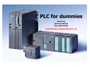
The programming look of the PLC requiredthat it be easily understood and used bymaintenance electricians and plant engineers. Asrelay-based control systems evolved and becamemore complicated, the use of physical componentlocation wiring diagrams also evolved into the relaylogic being shown in a ladder fashion. The controlpower hot wire would be the left rail, with thecontrol power neutral as the right rail. The variousrelay contacts, pushbuttons, selector switches, limitswitches, relay coils, motor starter coils, solenoidvalves, etc., shown in their logical order would formthe ladder’s rungs. It was requested that the PLCbe programmed in this Ladder Logic fashion.As Dick Morley laments in his memoirs , theprocess from idea to actual controller wasn’t allsmooth sailing.“The initial machine, which was neverdelivered, only had 125 words of memory, andspeed was not a criteria as mentioned earlier. Youcan imagine what happened! First, we immediatelyran out of memory, and second, the machine wasmuch too slow to perform any function anywherenear the relay response time. Relay responsetimes exist on the order of 1/60th of a second, andthe topology formed by many cabinets full of relaystransformed to code is significantly more than 125words. We expanded the memory to 1K andImage of Dick MorleyCourtesy of AutomationWorld.comthence to 4K. At 4K, it stood the test of time forquite a while.”Tom, our controls designer, recounts, “My experience in creating relay-based control systems,at that time, put me in the perfect position to be one of the first control system designers to use some ofthe very first programmable controllers to replace relay-based control systems. My first experience witha PLC happened to be with one of Bedford Associates competitor’s solid state devices. The unit wasprogrammed with a suitcase-sized programming device that required setting the instruction type and lineaddress and then pressing a button to burn a fuse link open in a memory chip to set the logic path. Oncethe programming was completed and tested, the PLC was able to perform the machine cycle operationin a very reliable manner. Unfortunately the PLC card rack was open in the rear with a mixture of 24VDC and 120 VAC power and signals. It didn’t take much for an electrician checking signals duringtroubleshooting to accidently short the 120 VAC to the 24 VDC and take out the entire PLC system.Being the first use of a PLC in a large corporation, the failure doomed the use of PLCs at thismanufacturing facility for a couple of years.”PLC Handbook7
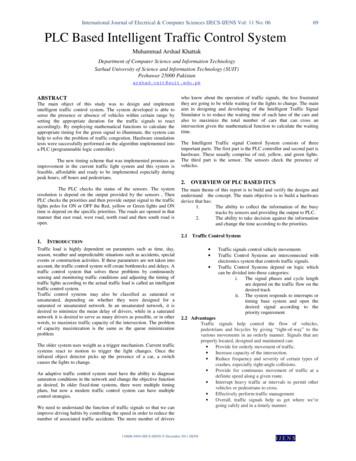
Eventually Dick Morely spun off a new company named Modicon and started to sell those firstPLCs, the Modicon 084 (named because it was prototype #84). It was the Modicon 084 that waspresented to GM to meet its criteria for its “standard machine controller.” Modicon started to sell the 084with very limited success. As Dick Morley puts it, “Our sales in the first four years were abysmal.” Butnevertheless the company continued to learn and develop. Eventually, Modicon would bring to life thecontroller that would change the industry forever, the Modicon 184. Dick Morley writes this about the184:“The thing that made the Modicon Company and the programmable controller really take off wasnot the 084, but the 184. The 184 was done in design cycle by Michael Greenberg, one of the bestengineers I have ever met. He, and Lee Rousseau, president and marketer, came up with aspecification and a design that revolutionized the automation business. They built the 184 over theobjections of yours truly. I was a purist and felt that all those bells and whistles and stuff weren’t “pure”,and somehow they were contaminating my “glorious design”, Dead wrong again, Morley! They werespecifically right on! The 184 was a walloping success, and it—not the 084, not the invention of theprogrammable controller—but a product designed to meet the needs of the marketplace and thecustomer, called the 184, took off and made Modicon and the programmable controller the company andindustry it is today.”Image Courtesy of RepairZone.comPLC Handbook8
The PLC in its teenage yearsThe first PLCs had the ability to work with input and output signals, relay coil/contact internal logic,timers and counters. Timers and counters made use of word size internal registers, so it wasn’t too longbefore simple four-function math became available. The PLC continued to evolve with the addition ofone-shots, analog input and output signals, enhanced timers and counters, floating point math, drumsequencers and mathematic functions. Having built-in PID (Proportional-Integral-Derivative) functionalitywas a huge advantage for PLCs being used in the process industry. Common sets of instructionsevolved into fill-in-the-blank data boxes that have made programming more efficient. The ability to usemeaningful Tag Names in place of non-descriptive labels has allowed the end user to more clearlydefine their application, and the ability to import/export the Tag Names to other devices eliminates errorsthat result when entering information into each device by hand.As the functionality of the PLC evolved, programming devices and communications also saw rapidgrowth. The first programming devices were dedicated, but unfortunately the size of suitcases. Later,handheld programming devices came into the picture, but soon were replaced with proprietaryprogramming software running on a personal computer. AutomationDirect’s DirectSOFT, developed byHost Engineering, was the first Windows-based PLC programming software package. Having a PCcommunicating with a PLC provided the ability to not only program, but also allowed easier testing andtroubleshooting. Communications started with the MODBUS protocol using RS-232 serialcommunications. The addition of various automation protocols communicating over RS-485, DeviceNet,Profibus, and other serial communication architectures have followed. The use of serial communicationsand the various PLC protocols also allowed PLCs to be networked with other PLCs, motor drives, andhuman to machine interfaces (HMI). Most recently Ethernet and protocols such as EtherNet/IP (forIndustrial Protocol) have gained tremendous com/PLC http://www.plcdev.com/plc timeline, http://www.plcdev.com/the birth of the plcPLC Handbook9
Chapter 3How to Choose a ControllerChoosing the most effective controller for your application depends on a number of factors. Theworksheet below serves as a checklist of things to consider when determining programmable controllerrequirements. It lists the most important areas to consider when choosing a system, as well as providesspace for recording determinations of your system needs. To print a copy, here is the PDF version of theWorksheet for Choosing a Controller.Step 1:Determine whether your system is new or existing:Will your system be installed from scratch or arethere existing products already installed? The restof your system will need to be compatible with newcomponents.Why this is important: Certain controllerproducts may not be compatible with others.Making sure your existing products are compatiblewith any new products you are researching willsave you time and money. Check appropriateentry.Step 2:Consider any environmental issues that will affectyour application (temperature, dust, vibration,codes specific to your facility, etc.).Why this is important: Certain environmentsmay affect the operation of a controller. Forexample, typical controllers have an operatingtemperature of 0-55 degrees Celsius (32-130degrees F). If your application will include anyextreme environmental conditions, or you havespecific codes at your facility that must be met,you will need to either research products that meetthose specifications or design the installation tomeet requirements. Check appropriate entry.PLC Handbook10
Step 3:Determine how many discrete devices yoursystem will have. Which types (AC, DC, etc.) areneeded?Why this is important: The number and type ofdevices your system will include is directly linkedto the amount of I/O that will be necessary for yoursystem. You will need to choose a controller thatsupports your I/O count requirements and hasmodules that support your signal types. Enterquantities and type based on corresponding fielddevices.Step 4:Determine how many analog devices your systemwill have. Which types (voltage, current,temperature, etc.) are needed?Why this is important: The number and type ofdevices your system will include is directly linkedto the amount of I/O that will be necessary for yoursystem. You will need to choose a controller thatsupports your I/O count requirements and hasmodules that support your signal types. Enterquantities and type based on corresponding fielddevices.Step 5:Determine whether your system will require anyspecialty features: Will your application requirehigh-speed counting or positioning? What about areal-time clock or other specialty feature?Why this is important: Specialty functions arenot necessarily available in a controller CPU or instandard I/O modules. Understanding the specialfunctions your system may perform will help youdetermine whether or not you will need topurchase additional specialty modules. Check allfeatures required.PLC Handbook11
Step 6:Determine the type of CPU you will need: Howmuch memory will your system require? Howmany devices will your system have (determinesdata memory)? How large is your program, andwhat types of instructions will your programinclude (determines program memory)? How fasta scan time do you need?Why this is important: Data memory refers to theamount of memory needed for dynamic datamanipulation and storage in the system. Forexample, counter and timer instructions typicallyuse data memory to store setpoints, currentvalues, and other internal flags. If the applicationrequires historical data retention, such asmeasured device values over a long period oftime, the size of the data tables required maydetermine the CPU model you choose. Programmemory is the amount of memory needed to storethe sequence of program instructions that havebeen selected to perform the application. Eachtype of instruction requires a specific amount ofprogram memory, typically defined in aprogramming manual. Applications that arebasically sequential in nature can rely on the I/Odevice rule of thumb to estimate program memory(five words of memory for each I/O device);complex applications will be more difficult to judge.If scan time is important in your application,consider the CPU processor speed as well asinstruction execution speed. Some CPUs arefaster at boolean logic but slower with datahandling instructions.If special functions such as PID are required, theCPU you select may make those functions easierto perform. For program memory required, followthis rule of thumb: 5 words of program memory foreach discrete device and 25 words for eachanalog device. Check or calculate all requirementsthat apply.PLC Handbook12
Step 7:Determine where your I/O will be located: Will yoursystem require only local I/O, or both local andremote I/O locations?Why this is important: If subsystems will beneeded at long distances from the CPU, you willneed a controller that supports remote I/O. Youwill also have to determine if the remote distancesand speeds supported will be adequate for yourapplication. Serial and Ethernet-based I/Ohardware are two typical choices available formost systems. This I/O may also be referred to asdistributed I/O, and may require a particularprotocol, such as Modbus.Enter number of physical locations needed, andif/what specific protocol may be required.Step 8:Determine your communication requirements: Willyour system be communicating to other networks,systems or field devices?Why this is important: Communication ports(other than the programming port) are not alwaysincluded with a controller. Knowing your systemcommunication requirements will help you choosea CPU that supports your communicationrequirements, or additional communicationmodules if necessary. Check any/allcommunications functions required.Determine your programming requirements: DoesStep 9:your application require only traditionalprogramming instructions, or are specialinstructions necessary?Why this is important: Certain controllers may notsupport every type of instruction. You will need tochoose a model that supports all instructions thatyou may need for a specific application. Forexample, built-in PID functions are much easier touse than writing your own code to perform closedloop process control. Typical instructions such astimers, counters, etc., are available in mostcontrollers; note any other special instructionsrequired here. Check any/all programmingfunctions required.PLC Handbook13
Chapter 4PLC HardwareWhat controls you? No, I’m not talking about your boss, your spouse or the government. Instead,think of your body as an industrial control system. Now, what controls you? Hopefully, you said yourbrain, although the heart is an acceptable answer sometimes. But for now, let’s focus on the brain andthe nervous system as well. Your body receives signals from your senses or nerves that travel throughthe spinal cord to the brain. Well, a PLC system operates the same way, with a brain (the CPU), a spine(the base or backplane), and the senses (I/O modules). Now, let’s take a closer look at each and discussfunctions, options and considerations.The Base-icsWe’ll start with the spine. In a PLC system, you have different optionswhen it comes to connecting I/O modules to the CPU. Some systems havea fixed style where the CPU comes with a fixed set of I/O points alreadyinstalled and dedicated connections already determined.Other PLC systems have a stackable style where the CPU and I/O modules are separate, butcome with connectors built in that are used to attach the components together. These connections formone continuous data bus throughout the system. This internal data bus is often referred to as abackplane.Another option with PLC hardware is the modular base configuration. With this style of PLC, aseparate base unit that holds the modular components is needed. Each module will seat into a slot onthe base unit that is used to connect the module to the backplane already installed in the base. Thesebases come with different numbers of slots and some with power supplies built in. Typically, the first twoleftmost slots are dedicated for the power supply and CPU.PLC Handbook14
One question to keep in mind with internal PLC connections is, “How easy are they to change?” Inother words, after all of the modules are installed, how easy is it to get them out? With the fixed style,you are just that, fixed, so no help there. Stackable PLC components can be changed, but you have tobreak the backplane connection for all the modules downstream of the module you wish to remove. Thatcould be an issue. The modular base configuration is by far the easiest to change. Simply slide themodule out and slide the new one in. Some of these PLCs even offer hot swapping, which means thatthe module change can be done with the PLC powered and with no interruption to the control process.The Ins and OutsNow, let’s look at the senses, the information providers, or, in the PLC’s case, the I/O modules.The I/O modules, and their respective end devices, allow the PLC to know and affect the current state ofthe process being controlled. There are many types of input and output modules available, but they canall be classified as analog, discrete or specialty I/O.Discrete I/O is the simplest of the bunch and provides the PLC with ON/OFF control. Used withboth AC and DC voltage ranges, they provide the CPU with a yes/no, true/false indication and allowsimple full ON or full OFF responses. On the input side, you would use discrete I/O for simple questionslike, “Is the box there?”, “Is the tank full?”, “Can I start this motor?” These input signals are provided bydevices such as photoeyes, proximity switches, E-stop pushbuttons, float switches, etc. For discreteoutputs, your command choices are either ON or OFF with nothing in between and are commonly usedfor stack lights, alarms, relays, solenoids, etc.One thing to consider with discrete I/Ois whether you need a sink, source or relayconfiguration. With sinking inputs/outputs, thePLC will provide the reference voltage(typically 0V) when completing the circuit.Sourcing inputs/outputs are the opposite andthe PLC will provide the source voltage, be it12VDC, 24VDC, 240VAC, etc. Relay typesdon’t provide either. They function just as arelay contact would, using an external sourceand connecting it to a load once activated.You can read more about sink/sourceconcepts in this blog.Sinking and Sourcing ConceptsMake the right choice the first time when selecting thetype of I/O points for your application by reviewingthese sinking and sourcing concepts.Visit: http://N2ADC.com/jhll2PLC Handbook15
Next up is analog. Analog I/O deals with the gray area betweenUnderstandingDiscrete andAnalog I/Ofull ON and full OFF that discrete I/O ignores. It provides the PLC withthe data it needs for precision control of a process. If you want to knowthe exact liquid level in a tank or you want to open a valve 1/3 of theway, analog is the answer. Analog signals come in a variety of rangesincluding: 0-20mA, 4-20mA, 0-10V, etc. RTD and thermocouplemodules are two analog modules that specialize in converting lowvoltage signals from temperature probes into usable data. Oneimportant factor to remember with analog modules is the resolution theyprovide. The higher the resolution, the higher the accuracy of the inputmeasurement or output response. To read more about discrete andanalog I/O, refer to this blog.Shed some light onthe differencesbetween discrete andanalog I/O for yourPLC applicationsVisit:N2ADC.com/ngipfThat leaves us with specialty I/O. This type of I/O includes special functions like high-speed andcommunication. High-speed modules are needed when the input/output data is comprised of highfrequency pulses. These modules can track input data, such as encoder signals, independent of theCPU scan, guaranteeing a moreaccurate pulse count. And high-speedoutputs can provide precision controlwith stepper motors used in motion orpositioning applications. Communicationmodules provide additionalcommunication ports/protocols that asystem may require: RS232, RS485,Ethernet, etc. They can also allow alocal PLC system to be expandedremotely, if the need arises.PLC Handbook16
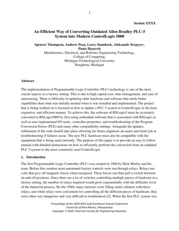
PLC PowerNow before we touch on the brain of the system, I’d like to detour a bit and discuss the PowerSupply. As mentioned earlier, the PLC power supply can be included with the base or it can be aseparate unit. They come in a variety of voltage ranges, including 12-24VDC and 110/220 VAC, andsupply a limited amount of amperage. It is very important that the power supply chosen is capable ofsupplying the CPU and I/O modules with the power they need. To ensure this, perform a power budgetanalysis and calculate the required current for your application. An example is shown below.PLC Handbook17
The CPUSo we have the connections made and the external data, now we need to know what to do with it.That is the job of the CPU (central processing unit). The CPU contains a microprocessor, memorystorage and other integrated circuits that are used to execute the control program, store logic data, andcommunicate to external devices. So what should the CPU hardware include? Well, for starters, theCPU will need some way to communicate and this is typically done using Ethernet, serial or USBcommunication ports. Serial ports are important since many existing networks use the
PLC Handbook 4 The input/output system is physically connected to field devices and pro