Transcription
Stick diagram and LayoutDiagram
INTRODUCTION Objectives:––––To know MOS layersTo understand the stick diagramsTo learn design rulesTo understand layout and symbolic diagrams Outcome:– At the end of this, will be able draw the stickdiagram, layout and symbolic diagram for simpleMOS circuitsUNIT – II CIRCUIT DESIGN PROCESSES
MOS LAYERSUNIT – II CIRCUIT DESIGN PROCESSES
STICK DIAGRAMS Objectives:– To know what is meant by stick diagram.– To understand the capabilities and limitations ofstick diagram.– To learn how to draw stick diagrams for a givenMOS circuit. Outcome:– At the end of this module the students will be abledraw the stick diagram for simple MOS circuits.UNIT – II CIRCUIT DESIGN PROCESSES
STICK DIAGRAMS VLSI design aims to translate circuit conceptsonto silicon. Stick diagrams are a means of capturingtopography and layer information using simplediagrams. Stick diagrams convey layer informationthrough color codes (or monochromeencoding). Acts as an interface between symbolic circuitand the actual layout.UNIT – II CIRCUIT DESIGN PROCESSES
STICK DIAGRAMS Does show all components/vias.– Via is used to connect higher level metals from metal connection It shows relative placement of components. Goes one step closer to the layout Helps plan the layout and routingA stick diagram is a cartoon of a layout.UNIT – II CIRCUIT DESIGN PROCESSES
STICK DIAGRAMS Does not show– Exact placement of components– Transistor sizes– Wire lengths, wire widths, tub boundaries– Any other low level details such asparasiticsUNIT – II CIRCUIT DESIGN PROCESSES
STICK DIAGRAMSStick Diagrams – NotationsMetal 1polyndiffpdiffCan also drawin shades ofgray/line style.Buried ContactContact CutUNIT – II CIRCUIT DESIGN PROCESSES
STICK DIAGRAMSNMOS ENCODINGUNIT – II CIRCUIT DESIGN PROCESSES
STICK DIAGRAMSCMOSENCODINGUNIT – II CIRCUIT DESIGN PROCESSES
STICK DIAGRAMSStick Diagrams – Some RulesRule 1:When two or more ‘sticks’ of the same type cross or toucheachotherthatrepresentselectricalcontact.UNIT – II CIRCUIT DESIGN PROCESSES
STICK DIAGRAMSStick Diagrams – Some RulesRule 2:When two or more „sticks‟ of different type cross or touch eachother there is no electrical contact.(If electrical contact is needed we have to show the connectionexplicitly)UNIT – II CIRCUIT DESIGN PROCESSES
STICK DIAGRAMSStick Diagrams – Some RulesRule 3:When a poly crosses diffusion it represents a transistor.Note: If a contact is shown then it is not a transistor.UNIT – II CIRCUIT DESIGN PROCESSES
STICK DIAGRAMSStick Diagrams – Some RulesRule 4:In CMOS a demarcation line is drawn to avoid touching of p-diffwith n-diff. All PMOS must lie on one side of the line and allNMOS will have to be on the other side.UNIT – II CIRCUIT DESIGN PROCESSES
STICK DIAGRAMSExamples of Stick DiagramsVdd 5VVdd 5VpMOSVoutVinVinnMOSUNIT – II CIRCUIT DESIGN PROCESSESVout
STICK DIAGRAMSExamples of Stick DiagramsVDDVDDXxxxXXXGndGndUNIT – II CIRCUIT DESIGN PROCESSESx
STICK DIAGRAMSExamples of Stick DiagramsUNIT – II CIRCUIT DESIGN PROCESSES
STICK DIAGRAMSExamples of Stick Diagrams* Note the depletion mode deviceVdd 5VVoutVinUNIT – II CIRCUIT DESIGN PROCESSES
STICK DIAGRAMSExamples of Stick DiagramsUNIT – II CIRCUIT DESIGN PROCESSES
STICK DIAGRAMSExamples of Stick DiagramsUNIT – II CIRCUIT DESIGN PROCESSES
STICK DIAGRAMSExamples of Stick DiagramsNOR gate and NAND using NMOS TransistorsUNIT – II CIRCUIT DESIGN PROCESSES
STICK DIAGRAMSExamples of Stick Diagramsf [(xy) z]‟ using NMOS TransistorsUNIT – II CIRCUIT DESIGN PROCESSES
STICK DIAGRAMSExamples of Stick DiagramsUNIT – II CIRCUIT DESIGN PROCESSES
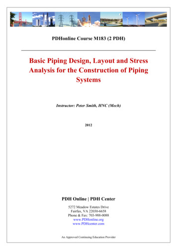
DESIGN RULES Why we use design rules?– Interface between designer and process engineer Historically, the process technology referred to thelength of the silicon channel between the source anddrain terminals in field effect transistors. The sizes of other features are generally derived as aratio of the channel length, where some may be largerthan the channel size and some smaller.– For example, in a 90 nm process, the length of the channel may be 90nm, but the width of the gate terminal may be only 50 nm.UNIT – II CIRCUIT DESIGN PROCESSES
DESIGN RULESUNIT – II CIRCUIT DESIGN PROCESSES
DESIGN RULES Allow translation of circuits (usually in stickdiagram or symbolic form) into actualgeometry in silicon Interface between circuit designer andfabrication engineer Compromise– designer - tighter, smaller– fabricator - controllable, reproducibleUNIT – II CIRCUIT DESIGN PROCESSES
DESIGN RULES Design rules define ranges for features– Examples: min. wire widths to avoid breaks min. spacing to avoid shorts minimum overlaps to ensure complete overlaps– Measured in microns– Required for resolution/tolerances of masks Fabrication processes defined by minimum channelwidth– Also minimum width of poly traces– Defines “how fast” a fabrication process isUNIT – II CIRCUIT DESIGN PROCESSES
DESIGN RULES Two major approaches:– “Micron” rules: stated at micron resolution.– rules: simplified micron rules with limitedscaling attributes. Design rules represents a tolerance which insuresvery high probability of correct fabrication– scalable design rules: lambda parameter– absolute dimensions (micron rules)UNIT – II CIRCUIT DESIGN PROCESSES
DESIGN RULES“Micron” rules All minimum sizes and spacing specified inmicrons. Rules don't have to be multiples of λ. Can result in 50% reduction in area over λbased rules Standard in industry.UNIT – II CIRCUIT DESIGN PROCESSES
DESIGN RULESLambda-based Design Rules Lambda-based (scalable CMOS) design rules definescalable rules based on (which is half of theminimum channel length)– classes of MOSIS SCMOS rules: SUBMICRON, DEEPSUBMICRON Stick diagram is a draft of real layout, it serves as anabstract view between the schematic and layout.UNIT – II CIRCUIT DESIGN PROCESSES
DESIGN RULESLambda-based Design Rules Circuit designer in general want tighter, smaller layoutsfor improved performance and decreased silicon area. On the other hand, the process engineer wants designrules that result in a controllable and reproducibleprocess. Generally we find there has to be a compromise for acompetitive circuit to be produced at a reasonable cost. All widths, spacing, and distances are written in theform 0.5 X minimum drawn transistor lengthUNIT – II CIRCUIT DESIGN PROCESSES
DESIGN RULESLambda-based Design Rules Design rules based on single parameter, λSimple for the designerWide acceptanceProvide feature size independent way of setting outmaskIf design rules are obeyed, masks will produce workingcircuitsMinimum feature size is defined as 2 λUsed to preserve topological features on a chipPrevents shorting, opens, contacts from slipping out ofarea to be contactedUNIT – II CIRCUIT DESIGN PROCESSES
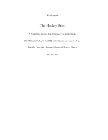
DESIGN RULES Minimum width of PolySi and diffusion line 2 Minimum width of Metal line 3 as metal lines run over amore uneven surface than other conducting layers to ensuretheir continuityMetalDiffusion3 2 2 UNIT – II CIRCUIT DESIGN PROCESSESPolysilicon
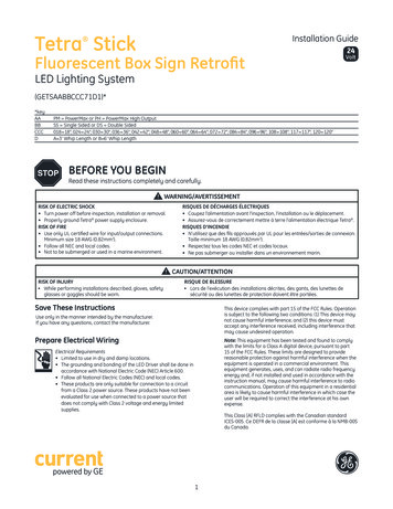
DESIGN RULES PolySi – PolySi space 2 Metal - Metal space 2 Diffusion – Diffusion space 3 To avoid the possibility oftheir associated regions overlapping and conductingcurrentMetal2 Diffusion2 3 UNIT – II CIRCUIT DESIGN PROCESSESPolysilicon
DESIGN RULES Diffusion – PolySi space To prevent the lines overlappingto form unwanted capacitor Metal lines can pass over both diffusion and polySi withoutelectrical effect. Where no separation is specified, metallines can overlap or crossMetalDiffusion UNIT – II CIRCUIT DESIGN PROCESSES
DESIGN RULES Metal lines can pass over both diffusion and polySi withoutelectrical effect It is recommended practice to leave between a metal edgeand a polySi or diffusion line to which it is not electricallyconnectedMetal PolysiliconUNIT – II CIRCUIT DESIGN PROCESSES
DESIGN RULES Recall– poly-poly spacing2 –diff-diff spacing3 (depletion regions tend to spread outward)–metal-metal spacing 2 –diff-poly spacing UNIT – II CIRCUIT DESIGN PROCESSES
DESIGN RULESButting ContactThe gate and source of a depletion device can be connected by amethod known as butting contact. Here metal makes contact toboth the diffusion forming the source of the depletion transistorand to the polySi forming this device‟s gate.Advantage:No buried contact mask required and avoids associated processing.UNIT – II CIRCUIT DESIGN PROCESSES
DESIGN RULESBuried ContactHere gate length is depend upon the alignment of the buriedcontact mask relative to the polySi and therefore vary by .PolySi 2 Buried contactChannel length 2 DiffusionUNIT – II CIRCUIT DESIGN PROCESSES
DESIGN RULESContact Cut Metal connects to polySi/diffusion by contact cut. Contact area: 2 X 2 Metal and polySi or diffusion must overlap this contactarea by l so that the two desired conductors encompass thecontact area despite any mis-alignment betweenconducting layers and the contact hole4 UNIT – II CIRCUIT DESIGN PROCESSES
DESIGN RULESContact Cut Contact cut – any gate: 2 apart Why? No contact to any part of the gate.4 2 UNIT – II CIRCUIT DESIGN PROCESSES
DESIGN RULESContact Cut Contact cut – contact cut: 2 apart Why? To prevent holes from merging.2 UNIT – II CIRCUIT DESIGN PROCESSES
DESIGN RULESUNIT – II CIRCUIT DESIGN PROCESSES
DESIGN RULES3 6 6 2 2 All device mask dimensions are based on multiples of , e.g., polysilicon minimumwidth 2 . Minimum metal to metal spacing 3 UNIT – II CIRCUIT DESIGN PROCESSES
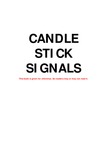
DESIGN RULESThinoxn-diffusionMetal 1p-diffusion3λ2λ3λ3λ2λ3λMetal 22λ4λ2λ2λ4λPolysilicon4λUNIT – II CIRCUIT DESIGN PROCESSES
DESIGN RULES Wells must surround transistors by 6 – Implies 12 between opposite transistor flavors– Leaves room for one wire trackUNIT – II CIRCUIT DESIGN PROCESSES
DESIGN RULES A wiring track is the space required for a wire– 4 width, 4 spacing from neighbour 8 pitch Transistors also consume one wiring trackUNIT – II CIRCUIT DESIGN PROCESSES
LAYOUTS Layer Types–––––––p-substraten-welln p Gate oxideGate (polysilicon)Field Oxide Insulated glass Provide electrical isolationUNIT – II CIRCUIT DESIGN PROCESSES
LAYOUTSN UNIT – II CIRCUIT DESIGN PROCESSESN
LAYOUTSTop view of the FET patternNMOSn n PMOSNMOSn n p PMOSp n-wellUNIT – II CIRCUIT DESIGN PROCESSESp p
LAYOUTSDesigning MOS ArraysABCyxABCyxUNIT – II CIRCUIT DESIGN PROCESSES
LAYOUTSParallel Connected MOS PatterningAxxBABXXXyyxAXXXXBAyUNIT – II CIRCUIT DESIGN PROCESSESyB
LAYOUTSThe CMOS NOT GateContactCutVpVpXxxXn-wellxXXGndGndUNIT – II CIRCUIT DESIGN PROCESSES
LAYOUTSThe CMOS NAND GateVpVpXXXa.bGndaa.bbXXGndaUNIT – II CIRCUIT DESIGN PROCESSESb
LAYOUTSThe CMOS NAND GateUNIT – II CIRCUIT DESIGN PROCESSES
LAYOUTSThe CMOS NOR GateUNIT – II CIRCUIT DESIGN PROCESSES
Stick diagram is a draft of real layout, it serves as an abstract view between the schematic and layout. Lambda-based Design Rules. DESIGN RULES UNIT –II CIRCUIT DESIGN PROCESSES Circuit designer in general want tighter, smaller lay