Transcription
Flexible Circuits, Inc.Design Guide222 Valley Rd., Warrington, Pa. 18976-2580 TEL: ( 215 ) 343-2300 FAX: ( 215 ) 343-2075Page 1 of 68
Flexible Circuits, Inc.Design Guide222 Valley Rd., Warrington, Pa. 18976-2580 TEL: ( 215 ) 343-2300 FAX: ( 215 ) 343-2075ForewordFlexible Circuits, Inc. produces high reliability flexible printed wiringinterconnects. We are a MIL-P-50884 and IPC 6013 certified manufacturer.To provide this type of performance level, certain design techniques andproper material selection are crucial for the manufacture of and optimizingfield performance. This guide along with direct contact with FlexibleCircuits, Inc. will provide the necessary information required for achievinga successful interconnect package from concept through installation.Page 2 of 68
Flexible Circuits, Inc.Design Guide222 Valley Rd., Warrington, Pa. 18976-2580 TEL: ( 215 ) 343-2300 FAX: ( 215 ) 343-2075INDEXPagesIntroduction .4-5Specifications .6-15Materials . 16-24Construction . 25-31Artwork . 32-41Miscellaneous:Stiffener/Reinforcements .43-44Desmear/Etchback .45-46Dynamic Flexing .47Silver Epoxy Shielding .48-49Surface Mount .50Bookbind 51-54Heat Sinks .55Pad Only Plating .56Solder Mask .57Eccobond Fillet (Rigid/Flex Transition Zone) .58Laser Cutting/Skiving .59Data Sheets Page 3 of 6860-68
Flexible Circuits, Inc.Design Guide222 Valley Rd., Warrington, Pa. 18976-2580 TEL: ( 215 ) 343-2300 FAX: ( 215 ) 343-2075Flexible Circuit or Rigid Board?The most compelling difference between flexible circuits versus rigid circuits is flexibility.Flexible circuits are usually much thinner and are able to conform to the spacing limitations andenvironments into which they are installed.Advantages of using flexible circuitry:1) They can conform to three dimensional spacing limitations.2) They have mobility (can be used where movement is required).3) They are much thinner, thus more conductive layers can be added and will fit into tighterspaces.4) They are much lighter in weight.Disadvantages of using flexible circuitry:1) They are generally much more expensive as a unit price.2) They are more fragile. They can be subject to tearing if not properly handled.3) Installation of terminals, connectors, etc. may require an additional stiffening material bondedto the flexible circuit.4) “Z” axis expansion must be addressed during thermal exposure.Page 4 of 68
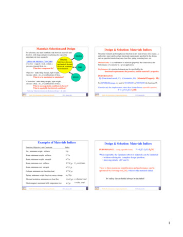
Flexible Circuits, Inc.Design Guide222 Valley Rd., Warrington, Pa. 18976-2580 TEL: ( 215 ) 343-2300 FAX: ( 215 ) 343-2075Flexible Circuit or Round Wire?Perhaps a short review of the advantages of flexible circuitry will help you make a decision.1. Less weight and bulk when used as a direct round wire replacement.2. It will virtually eliminate wiring errors and subsequently the need for trouble shooting wiringerrors.3. When all the costs of manufacturing, assembly, installation, and trouble shooting/repair areconsidered, a lower “end-use cost” is usually obtained with flexible circuitry.4. Greater environmental resistance against corrosion, moisture and other atmosphere hazardsbecause of the encapsulation of the copper conductors.5. Improved durability because the materials used are highly resistant to flexing and tension.6. Better adaptability. Able to fit into operational configurations where printed circuit boardssimply cannot fit.Why Settle for This? When You Can Have This!!!An actual unit, wired with old fashionedround wire.Same unit, using a 16 Layer flexiblecircuit.Page 5 of 68
Flexible Circuits, Inc.Design Guide222 Valley Rd., Warrington, Pa. 18976-2580 TEL: ( 215 ) 343-2300 FAX: ( 215 ) 343-2075SPECIFICATIONSPage 6 of 68
Flexible Circuits, Inc.Design Guide222 Valley Rd., Warrington, Pa. 18976-2580 TEL: ( 215 ) 343-2300 FAX: ( 215 ) 343-2075The industry generally had accepted two specifications for the manufacture of flexible printed wiringboards, “MIL-P-50884” for military/aerospace field and “IPC” for industrial/commercial/medical fields.Today the industry is moving away from the military specifications and adopting the “IPC” specifications.IPC has created a complete array of specifications for manufacturing, assembling, and testing of flexibleprinted wiring boards for all performance levels. “IPC-6013” is the new fabrication and performancespecification for flexible printed wiring boards that replaces MIL-P-50884.Below is a list of the MIL-Specs and the IPC-Specs most commonly L-Q-9858MIL-P-81728MIL-P-55110QQ-N-290Flex Manufacturing and PerformanceFlex Design StandardSampling Procedures and Inspection TablesMarking for Shipment and StorageIdentification for MarkingTest Methods for Electronic EquipmentSoldering and AssemblyCalibration System RequirementsEngineering DrawingsEngineering Drawing PracticesDimensioning and TolerancingPlastic Sheet, Laminate, Metal Clad (for PWBs)Copper Plating (Electrodeposited)Ink Marking, Epoxy BaseGold Plating (Electrodeposited)Inspection System RequirementsQuality Program RequirementsPlating Tin Lead (Electrodeposited)Printed Wiring BoardsNickel Plating (Electrodeposited)Page 7 of 68
Flexible Circuits, Inc.Design Guide222 Valley Rd., Warrington, Pa. 18976-2580 TEL: ( 215 ) 343-2300 FAX: ( 215 ) J-STD-004J-STD-005J-STD-006Qualification and Performance Specification for Flexible Printed BoardsTerms and DefinitionsMetal Foil for Printed Wiring ApplicationsFlexible Bare Dielectrics for Use in Flexible Printed WiringSpecification for Adhesive Coated Dielectric Films For Use as Cover Sheetsfor Flexible Printed WiringFlexible Metal Clad Dielectrics for use in Fabrication of Flexible Printed WiringQualification and Performance of Permanent Solder MaskGeneric Standard on Printed Board DesignSectional Design Standard for Flexible Printed BoardsLaminate/Prepreg Materials Standard for Printed BoardsGeneric Performance Specification for Printed BoardsQualification and Performance Specification for Rigid Printed BoardsRequirements for Soldered Electrical and Electronics AssembliesSolderability Tests for Component Leads, Terminations, Lugs, Terminals and WiresSolderability Tests for Printed BoardsRequirements for Soldering FluxesGeneral Requirements and Test Methods for Electronic Grade Solder PasteGeneral Requirements and Test Methods for Soft Solder Alloys and Fluxed andNon-Fluxed Solid Solder for Electronic Soldering Applications.Page 8 of 68
Flexible Circuits, Inc.Design Guide222 Valley Rd., Warrington, Pa. 18976-2580 TEL: ( 215 ) 343-2300 FAX: ( 215 ) 343-2075Comparison of the new IPC-6013 to the old MIL-P-50884(major highlighted differences)1) Ease of use:IPC contains an index and paragraphs are easy to follow. Specification tries to promote communicationbetween manufacturer and user.MIL is not user friendly and requires user to refer to many different paragraphs.2) How current are specifications:IPC contains all updated specifications.MIL needs updating to current specifications.3) Specification addresses different performance level requirementsIPC contains three performance levels (1,2,3).Class 1- general useClass 2 - industrial useClass 3 – high reliabilityMIL has one performance level only (basically high reliability). This can result in unnecessary testingand other costs when lower performance requirements may satisfy the application.4) Rigid/Flex transition zoneIPC allows for visual imperfections in this zone that do not cause any functional degradation.MIL does not address this area. Defaults to surface and sub-surface imperfections whichdo not adequately address anomalies that frequently occur in this zone. This results inunwarranted rejections or indecision.5) Foreign Material (conductive and non-conductive)IPC translucent foreign material is acceptable. All other foreign material is acceptable providedit is not closer than the minimum spacing on the drawing.MIL must not be conductive, not be .031”, not reduce spacing 25%, and not propagate. Thisresults in rejections that in most cases do not affect performance.6) Measling and CrazingIPC did an extensive study and found that these conditions do not cause any degradation in theperformance of the printed wiring board and therefore concluded that “measling” and“crazing” are not rejectable items.MIL measling and crazing must conform to sub-surface imperfections requirements. This results inunwarranted rejections that were proven not to have any performance degradation.7) Solder WickingIPC specifically limits the amount of solder wicking by class.MIL does not address this condition, therefore results in indecision.Page 9 of 68
Flexible Circuits, Inc.Design Guide222 Valley Rd., Warrington, Pa. 18976-2580 TEL: ( 215 ) 343-2300 FAX: ( 215 ) 343-20758) Minimum Annular RingIPC depends on Class. Class 3 is .002” external and .001” internal. Other classes are less stringent.This recognizes designs are becoming smaller and require tighter geometry’s.MIL .005” min. for external and .002” min. for internal.9) Solder Coating and Fused Tin-LeadIPC solder finish must have coverage and be solderableMIL solder coating must be .0003” min at the crest on the surface, .0001” min. at the crest in thehole and coverage at the “knee” of the hole. Tin Lead coating must be .0003” min. before fusing.HASL has never met MIL-P-50884, however it is method most widely used for soldering today.10) Organic Solderability Preservative (OSP) coatingsIPC allows use of this technology.MIL does not address this technology.11) Copper Thickness after processingIPC minimum copper foil thickness after processing is clearly definedMIL not addressed. There is no minimum accepted value for how much copper can be removed duringProcessing.12) QualificationIPC to be agreed upon by user and supplier. Can be pre-production samples, production samples,test specimens (i.e. IPC-A-41, 42 or 43), or based on documentation from testing of specimensfurnished on similar product. There is no QPL listingMIL must submit test specimens using artwork pattern IPC-A-41,42 or 43 and pass a QualificationCertification testing every 3 years. A QPL list is generated.13) Coupon DesignIPC Coupon design is per IPC-2221. Coupon design tries to represent circuit pattern.MIL Coupon design per MIL-STD-2118. Coupon does not represent the circuit.Page 10 of 68
Flexible Circuits, Inc.Design Guide222 Valley Rd., Warrington, Pa. 18976-2580 TEL: ( 215 ) 343-2300 FAX: ( 215 ) 343-2075IPC-6013 Wiring TypesType 1 Single-sided flexible printed wiring containing on conductive layer with or withoutstiffeners.Type 2 Double-sided flexible printed wiring containing two conductive layers with platedthrough holes, with or without stiffeners.Type 3 Multilayer flexible printed wiring containing three or more conductive layers withplated –through holes, with or without stiffeners.Type 4 Multilayer rigid and flexible material combinations containing three or moreconductive layers with plated-through holes.Type 5 Flexible or rigid-flex printed wiring containing two or more conductive layers withoutplated-through holes.Installation UsesUse A Capable of withstanding flex during installationUse B Capable of withstanding continuous flexing for the number of cycles as specified onthe procurement documentation.Use C High temperature environment (over 105 degrees C)Use D UL RecognitionNote: If Performance Class and Installation Usage are not specified, then the default selectionswill be:Performance Class – Class 2Installation Usage – Use APage 11 of 68
Flexible Circuits, Inc.Design Guide222 Valley Rd., Warrington, Pa. 18976-2580 TEL: ( 215 ) 343-2300 FAX: ( 215 ) 343-2075IPC-4101Specification for Base Materials for Rigid and Multilayer Printed BoardsAs the Printed Circuit Industry moves away from Military Specifications, this created a need tofor an IPC specification for rigid materials. This specification covers the performance requirements for rigidlaminates and prepregs used for the manufacture of rigid boards, rigid multilayer boards andflexible rigid/flex boards.This specification is based on the canceled specification MIL-S-13949. It basically provides theindustry with performance criteria that is equivalent to MIL-S-13949. However, it eliminates some ofthe redundant testing and costs associated with those tests.What does this mean to the User?Basically no impact except that drawings should now specify the above materials to be perIPC-4101 in lieu of canceled MIL-S-13949. Certification can only be made to IPC-4101. There is no longerany certification to MIL-S-13949.Shown in the next pages are the major differences between the IPC-4101 and MIL-S-13949.Page 12 of 68
Flexible Circuits, Inc.Design Guide222 Valley Rd., Warrington, Pa. 18976-2580 TEL: ( 215 ) 343-2300 FAX: ( 215 ) 343-2075Comparison of the IPC-4101 to the canceled MIL-S13949(major highlighted differences)General Information DifferencesPrepregs and laminates are on the same slash sheet.Slash sheets are recognized by “families” with open spaces for new materials that fit that family.The entire specification is in metric with no English references.The latest test methods are attached to the document.Paragraph 1.2.2Laminates can be ordered as dielectric space (without copper foil) or as an overall thickness(including copper foil). Currently laminates can only be ordered as a dielectric space.Table 1The copper foil table now includes type “R” (reverse treated electrodeposited) for grade 1 andType “S” (reverse treated electrodeposited) for grade 3.Paragraph 1.2.5 and 3.8.3.1.2Surface quality class now includes a “D” designation which provides the most stringent surfacequality call out. No pits, dents or epoxy spots over 5 mils. MIL-S-13949 has “B” as thetightest class which allow 1 pit up to 15 mils.Paragraph 1.2.7Prepregs are ordered using 3 parameters (resin content, resin flow, and the “optional” parameter)Prepregs can be tested by using new test methods such as rheology, % cure, or delta H.Paragraph 3.1.2Quality conformance testing is conducted as determined by the current Manufacturers QualitySystem. Changes in the testing frequencies can be made by following the guidelines inIPC-PC-90. In the absence of a “Manufacturing Quality System”, conformance testing isconducted at the same frequency as MIL-S-13949.Page 13 of 68
Flexible Circuits, Inc.Design Guide222 Valley Rd., Warrington, Pa. 18976-2580 TEL: ( 215 ) 343-2300 FAX: ( 215 ) 343-2075Paragraph 3.1.5 and 3.3Self declaration form IPC-LQP-1730 is a pre-requisite to certifying to IPC-4101. The documentIPC-LQP-1730 will be published by the IPC at the same time as the IPC-4101SpecificationParagraph 3.1.7 and 3.4Qualification sample testing must be conducted by the supplier at any IPC-QL-653 approvedlaboratory. The qualification data must be summarized and readily available for review.The qualification testing regime is the same as prescribed by MIL-S-13949.Paragraph 3.4.1A “thin” laminate specimen 10 mils or less qualifies all thin laminates (30 mils or less).A “thick” laminate specimen greater than 30 mils qualifies all thick laminates.Paragraph 3.4.2For a given slash sheet, the thinnest prepreg qualifies all the thicker prepregs.Table 5Table 5 now includes Delta Tg and average X/Y CTE as optional tests.The test method for flammability has been changed from the “MIL” method to the standard “UL”method 94.Table 6Electrical tests and some environmental tests are performed on prepregs after pressing into aThin laminate.Prepreg testing for flammability is only conducted as a thin laminate specimen.Paragraph 3.9.1.1Peel strength is called out as a single value for 35 micron foil. Foil weight greater than 35microns must meet the required value for 35 micron. Foils less than 35 micron may beplated up to 35 micron and tested as is the current specified procedure in MIL-S-13949.Page 14 of 68
Flexible Circuits, Inc.Design Guide222 Valley Rd., Warrington, Pa. 18976-2580 TEL: ( 215 ) 343-2300 FAX: ( 215 ) 343-2075Paragraph 3.9.1.2Dimensional stability is now specified as a nominal value with a tolerance range. The suppliermust provide the nominal value for dimensional stability for each construction. Currentlythe MIL-S-13949 specification uses zero as the nominal value. IPC-4101 will rewardconsistency of dimensional movement.Paragraph 3.9.2.2.6Gel time is an optional test. It can be replaced with other characterization tests if desired suchAs rheological flow, cure %, or Delta H.Paragraph 3.9.2.2.8Volatile content is an optional test.Paragraph 3.10.2.3Dicy Crystals is an optional test.Paragraph 3.15MSDS forms must be available for materials supplied under this specification.Paragraph 5.2The supplier is responsible for establishing written guidelines for their authorized distributors.Page 15 of 68
Flexible Circuits, Inc.Design Guide222 Valley Rd., Warrington, Pa. 18976-2580 TEL: ( 215 ) 343-2300 FAX: ( 215 ) 343-2075MATERIALSPage 16 of 68
Flexible Circuits, Inc.Design Guide222 Valley Rd., Warrington, Pa. 18976-2580 TEL: ( 215 ) 343-2300 FAX: ( 215 ) 343-2075Selection of MaterialsMaterials are one of the most important ingredient in determining the circuit’s performanceand life expectancy. Materials should be selected based upon the following criteria:What is the circuit’s function?What environment will the circuit be expected to operate in?What is the interconnection method?What is the life expectancy?What is the cost to produce?FCI has a vast knowledge and experience in matching the right material for the particular application.We use only the highest grades of materials. These next pages will describe these materials and theirperformance.Page 17 of 68
Flexible Circuits, Inc.Design Guide222 Valley Rd., Warrington, Pa. 18976-2580 TEL: ( 215 ) 343-2300 FAX: ( 215 ) 343-2075Flexible Metal Clad LaminateFlexible Metal Clad Laminates provide the base material (conductive and dielectric layers) for uponwhich flexible printed wiring boards can be produced.Types:Types are listed in IPC-FC-241. There are two(2) types of laminates that are typically used:1) A composite of polyimide film, acrylic adhesive, and copper foil.2) A composite of polyimide film and copper foil (no adhesive, this is commonlyReferred to as “adhesive-less” laminate.The first type is still the workhorse of the industry and is mostly used on Types 1, 2, 3, 5 andlow layer count Type 4 (rigid/flex) application.The second type is becoming more widely used especially on high layer count Type 4’s whereexcessive “z-axis” expansion of the materials during thermal exposure can cause platedthrough hole failure. There are other areas where this material proves to be advantageoussuch as in high dynamic flexing applications.Material AvailabilityMaximum sheet size (in.)Polyimide film thickness (mils)Copper foil weight (oz.)Adhesive thickness (mils)24 x 36 (FCI typically uses 18 x24 sheets)1, 2, 3, or 5½, 1, or 21*Other materials are available as special orders*Adhesive is available with a flame retardant called “FR” typePage 18 of 68
Flexible Circuits, Inc.Design Guide222 Valley Rd., Warrington, Pa. 18976-2580 TEL: ( 215 ) 343-2300 FAX: ( 215 ) 343-2075Adhesive Coated Kapton (Covercoat)Adhesive coated Kapton is the material used for providing a dielectric layer over the flexibleprinted wiring conductive surfaces
As the Printed Circuit Industry moves away from Military Specifications, this created a need to for an IPC specification for rigid materials. This specification covers the performance requirements for rigid laminates and prepregs used for the manufacture of rigid boards, rigid mul