Transcription
i n n o va ve co m p o n e nt s fo r i n s p i re d d e s i g n sFor Use With AISC 360 and 341.PRODUCTDATASHEETS
CONTENTSUNIVERSAL PIN CONNECTOR 3ARCHITECTURAL TAPER 5ARCHITECTURAL TAPER UNIVERSAL PIN7CONNECTOR TIMBER END CONNECTOR 8DIABLO BOLTED SPLICE10HIGH STRENGTH CONNECTOR 13
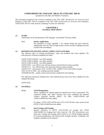
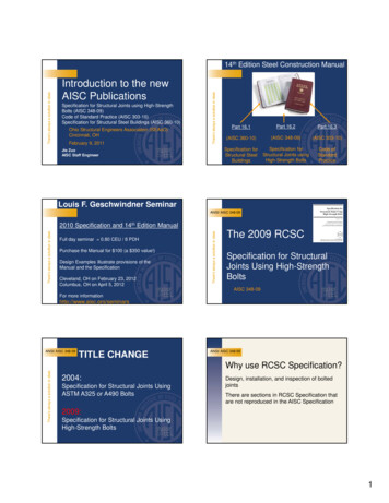
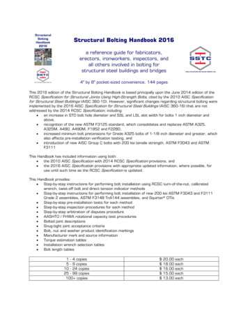
Universal Pin ConnectorsUNIVERSAL PINCONNECTOR TMi n n o va ve co m p o n e nt s fo r i n s p i re d d e s i g n nalW45 60 jDG’ n]j[in]Dpin[in]UPC-3.5003 1/232N/A15/161/25/88 1/47/161 1/2UPC-4.000L43 1/22 1/4N/A15/161/25/89 1/87/161 1/2UPC-4.00043 3/42 1/41 1/161 7/163/47/89 7/85/81 3/4UPC-5.5635 9/165 1/43 3/161 9/161 15/167/87/812 15/163/42UPC-6.6256 5/86 1/43 3/41 13/162 3/161 1/8115 3/43/42 3/4UPC-8.6258 5/884 7/82 1/162 13/161 1/8119 5/83/43UPC-10.7510 3/49 1/25 3/42 1/162 13/161 1/4123 7/83/43 3/4UPC-12.7512 3/4116 5/82 1/162 13/161 1/4128 1/43/44 1/2UPC-14.0014127 1/42 1/162 13/161 3/8131 3/43/45UPC-16.001613 1/47 7/82 1/162 13/161 3/8134 5/83/46UPC-24.00242112 3/46 1/16N/A2 15/161 1/252 3/41 3/88 1/2TypicalAssemblyAssemblyTypicalLmemberXtHSSHSS XX.XX ØaLLHSSCAST CONNEXUNIVERSAL PIN CONNECTORUPC-XX.XXPJP, AESSEs ma ng required length of HSS:LHSS Lmember - 2(L - a X)X 2g 3(tHSS)When using these equa ons to es mate the length of the HSS required (LHSS) fora given element, note that the actual HSS thickness (tHSS) can be significantlythinner than the nominal value. Refer to the relevant HSS or Pipe specifica on.Page 1 of 2Page 3PRINTED ON DD-MM-YYYYPRINTED: 01-08-2020g
UNIVERSAL PINCONNECTOR i n n o va ve co m p o n e nt s fo r i n s p i re d d e s i g n ConnectorsAvailableLoad and Resistance Factor Design (LRFD)Tensile StrengthThe pin connec on detail shown offers a factored tensile strength equal tothe lesser of:a) φPn in the table below,b) the factored strength of the weld between the HSS member andthe connector, andc) the factored tensile yield strength of the connec ng HSSmemberAllowable Stress Design (ASD)Tensile CapacityThe pin connec on detail shown offers an allowable tensile capacity equalto the lesser of:a) Pn/Ω in the table below,b) the allowable capacity of the weld between the HSS member andthe connector, andc) the allowable tensile yield capacity of the connec ng HSSmemberCompressive StrengthThe pin connec on detail shown offers a factored compressive strengthequal to the lesser of:a) φPn in the table below,b) the factored strength of the weld between the HSS member and theconnector,c) the factored overall compressive strength of the pin-ended HSSmember, andd) the factored buckling strength of the gusset plateCompressive CapacityThe pin connec on detail shown offers a allowable compressive capacityequal to the lesser of:a) Pn/Ω in the table below,b) the allowable capacity of the weld between the HSS member and theconnector,c) the allowable overall compressive capacity of the pin-ended HSSmember, andd) the allowable buckling capacity of the gusset plateSOLID PIN:Dpin : Diameter of pin; diameter of pin hole not more than1/32” larger than pinActual shaped gussetWg,minGUSSET PLATE:tg : thickness of gusset plateag,min : min gusset plate end distance for max design loadag,max : max gusset plate end distance to fit within connectorWg,min : min gusset plate width at pin for max design load45 CONNECTOR:Specified minimum yield strengthSpecified minimum tensile strengthagMin. gusset dimsFy 50 ksiFu 80 ksitgag,min[in]ag,max[in]Dpin[in]tg[in]3 1/242 1/42 1/23 1/43 5/84 7/85 1/26 7/88 3/892 3/42 3/43 5/84 3/165 3/86 1/87 3/88 7/8101 1/21 1/27/87/89 7/81310 3/415 3/45 1/45 7/87 7/8911 1/413 5/814 1/217 1/2211 3/422 3/433 3/44 1/2568 1/2A36 gussetφPn[kips]6464851461 292324265832478389165211 1/2A572 Gr. 42 ]50506611318222728434037868028604541906A572 Gr. 50 s]56597912321727033840545081028605401906Nominal strengths have been determined using AISC 360-10.Pn: Nominal strengthEqual to minimum strength of the connector, min. sized gusset, and pin using Sec ons D5.1, D2a, E3, J4.2 and J7a.Page 2 of 2Page 4PRINTED ON 20-07-2020PRINTED: 0UPC-24.00Wg,min[in]
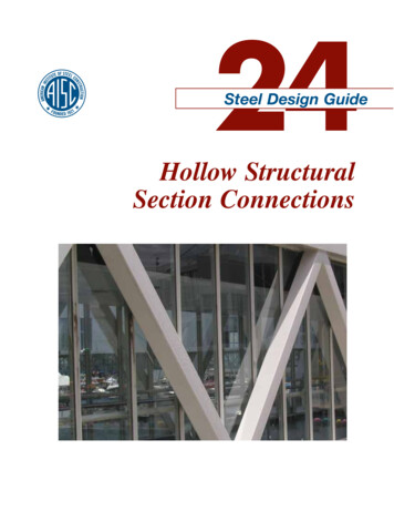
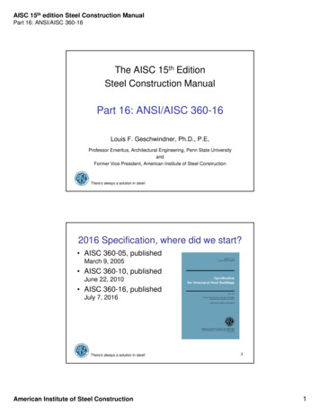
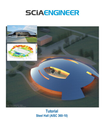
Architectural TapersARCHITECTURALTAPER TMi n n o va ve co m p o n e nt s fo r i n s p i re d d e s i g n sNominal Connector DimensionsNominalDimensions60 jD2D1ART-6.625ART-8.625, 10.75, 12.75, 16.00, in]j[in]ART-6.6256 5/83/44 1/4N/A143/45/8ART-8.6258 5/87/85 13/162 1/16183/43/4ART-10.75 10 3/47/86 7/82 11/3222 1/213/4ART-12.75 12 3/47/88 13/16 2 17/3226 1/213/4ART-16.00167/810 15/16 2 15/1633 1/21 1/23/4ART-18.001813/1612 15/16 2 15/1633 1/21 1/23/4TypicalTypical AssemblyLmemberXtHSSHSS XX.XX ØLLHSSCAST CONNEXARCHITECTURAL TAPERART-XX.XXPJP, AESSEs ma ng required length of HSS:LHSS Lmember - 2(L X)X 2g 3(tHSS)When using these equa ons to es mate the length of the HSS or Pipe required (LHSS)for a given element, note that the actual HSS or Pipe thickness (tHSS) can be significantlythinner than the nominal value. Refer to the relevant HSS or Pipe specifica on.Page 1 of 2Page 5PRINTED ON 20-07-2020PRINTED: 03-07-2019g
ARCHITECTURALTAPER i n n o va ve co m p o n e nt s fo r i n s p i re d d e s i g n e StrengthLoad and Resistance Factor Design (LRFD)Allowable Stress Design (ASD)The taper shown offers a factored strength equal tothe lesser of:a) LRFD values in the table below,b) the factored strengths of the joints between theconnector and other steel a achments (HSS, baseplate, etc.), andc) the factored strength of the overall member.The taper shown offers an available capacity equalto the lesser of:a) ASD values in the table below,b) allowable capacity of the joints between theconnector and other steel a achments (HSS, baseplate, etc.), andc) the available capacity of the overall member.ASDMn/Ω[k. ] φPn[kips]LRFDφMn**[k. 91373ART-18.0019629015921306599394*φVnPn/Ω[kips] [kips] ***Vn/Ω[kips]Specified minimumyield strengthFy 50 ksiSpecified minimumtensile strengthFu 80 ksiThe values reported are factored strengths or allowable capaci es for single-ac on loading (axial, flexural, orshear). The engineer shall consider the combined ac on of axial forces, bending and shear forces. Refer to AISCChapter H.Nominal strengths have been determined using AISC 360-10* Pn : Nominal axial compressive or tensile strength:Equal to the squash load: the minimum value determined from equa on D2-1.The governing gross-sec on of the taper is Ag π · t1(D1 - t1) Vn : Nominal shear strengthEqual to minimum value determined from equa on G6-1.The governing shear area of the taper is Av Ag / 2 π · t1(D1 - t1) / 2;The cri cal shear stress was taken as Fcr 0.6FyPage 6Page 2 of 2PRINTED ON 20-07-2020PRINTED: 03-07-2019**Mn : Nominal flexural strength:Equal to minimum value determined from equa on F8-1.The governing plas c sec on modulus of the taper is Z (D23 - (D2 - 2t2)3 ) / 6; or Z D23/ 6 for ART-6.625
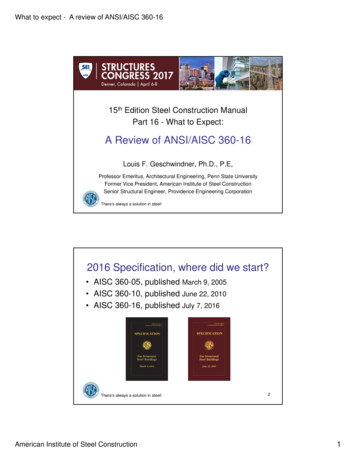
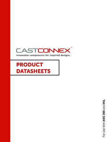
ARCHITECTURAL UNIVERSALTAPERi n nArchitecturalo va ve co m p o n e ntTaperss fo r i n s p i red d e s i gUniversalnswithPin ConnectorsPIN CONNECTOR nsionsD1jsD1[in]D2[in]L[in]s[in]j[in]ART-6.625 UPC-4.000L6 5/8421 5/83/45/8ART-6.625 UPC-4.0006 5/8422 23/323/45/8ART-8.625 UPC-5.5638 5/85 9/1629 1/323/43/4ART-10.75 UPC-6.62510 3/46 5/835 13/1613/4ART-12.75 UPC-8.62512 3/48 5/842 9/1613/4ART-16.00 UPC-10.75161 1/23/460 LD210 3/4 52 15/16Universal Pin Connector and Architectural Taper are supplied separately.Fabricator must weld the two pieces together to form the connec on assembly.AvailableAxialAxialStrengthof ConnectorsAvailableStrengthof ConnectorsTypicalTypicalAssemblyAssemblyStrengths governed by associated Universal PinConnector. Refer to the appropriate Universal PinConnector data sheet.LmemberXLARTto HSStHSSHSS XX.XX ØLHSSPJP, AESSCAST CONNEX ARCHITECTURALTAPER UNIVERSAL PIN CONNECTORART-XX.XX UPC-XX.XXPJP, AESSEs ma ng required length of HSS:LHSS Lmember - 2(L X)X 2g 3(tHSS)When using these equa ons to es mate the length of the HSS or Pipe required (LHSS)for a given element, note that the actual HSS or Pipe thickness (tHSS) can be significantlythinner than the nominal value. Refer to the relevant HSS or Pipe specifica on.Page 1 of 1Page 7PRINTED ON 20-07-2020PRINTED: 05-03-2017gUPCto ART
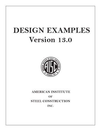
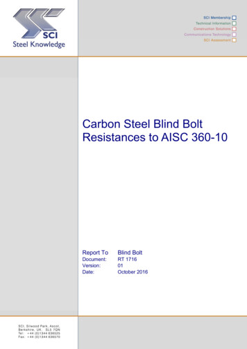
Timber End ConnectorsTIMBER ENDCONNECTOR TMi n n o va ve co m p o n e nt s fo r i n s p i re d d e s i g n WW[in]L[in]a[in]G[in]t[in]Dpin[in]TEC-6.756 3/4 4 1/8 9 5/16 2 1/41 1/811 1/2TEC-8.758 3/4 5 1/8 13 1/8 2 1/21 3/8 1 1/4TEC-10.75 10 3/4 7 1/8 15 1/8 3 1/8tG21 5/8 1 1/2 2 1/2TEC-10.75/2in1/4in1/2inTEC-8.751TEC-XX.XX connectedwith screwsCompression onlyLmemberCAST CONNEXTIMBER END CONNECTORTEC-XX.XXTimber supplier to coordinatewith casting supplierLPage 1 of 2Page 8aPRINTED ON 20-07-2020PRINTED: 12-02-2019TEC-XX.XX connected withglued-in rods and nutsCompression onlyTEC-6.75TEC-XX.XX with weldedon knife plate and boltsTension and/or 75/4in1TEC-10.75TypicalAssembliesAssemblyTypical
TIMBER ENDTimber End Connectors CONNECTORi n n o va ve co m p o n e nt s fo r i n s p i re d d e s i g n leforforCompressionOnlyConnections10 34 ""3 15168 34 "6 34 ""3 "2 321 1532R3916 "TEC - 6.75.5 "37 3917" TYP.3252 32TEC - 8.75"2 131635 17" TYP.32"30 4 14 "R4 916 "9 "2 32TEC - 10.751 5817" TYP.32R2916 engthof ofConnectorsLoad and Resistance Factor Design (LRFD)Allowable Stress Design (ASD)The pin connec on detail shown offers a factored axial strength equal tothe lesser of:a) φPn in the table below,b) the factored strength of the mber member-to-connector connec onc) the factored strength of the connec ng mber member, andd) the factored buckling strength of the gusset plateThe pin connec on detail shown offers an allowable tensile capacity equal to thelesser of:a) Pn/Ω in the table below,b) the allowable capacity of the mber member-to-connector connec onc) the allowable tensile capacity of the connec ng mber member, andd) the allowable buckling capacity of the gusset plateSOLID PIN:Dpin : Diameter of pin; diameter of pin hole not more than1/32” larger than pinActual shaped gussetGUSSET PLATE:tg : thickness of gusset plateag,min : min gusset plate end distance for max design loadag,max : max gusset plate end distance to fit within connectorWg,min : min gusset plate width at pin for max design loadCONNECTOR:Specified minimum yield strengthSpecified minimum tensile strengthagMin. gusset dimstgA36 gussetTEC-6.75TEC-8.75TEC-10.75Page 9Wg,min[in]ag,min[in]4 1/84 7/862 3/433 5/8ag,max[in]3341/21/2Dpin[in]1 1/222 1/2tg[in]11 1/41 1/2φPn[kips]72.9121182Pn/Ω[kips]48.681.0121A572 Gr. 42 gusset A572 Gr. 50 gussetφPn[kips]85.1142213Page 2 of ps]67.5112169Fy 40 ksiFu 70 ksiNominal strengths have beendetermined using AISC360-16.Pn: Nominal Compressive orTensile strength: Equal to min.strength of the connector,min. sized gusset, and pinusing Sec ons D2a, D5.1, E3,J4.2 and J7a.PRINTED:12-02-2019PRINTEDON 20-07-2020Wg,min
DIABLO BOLTEDSPLICE Diablo Bolted SpliceTMi n n o va ve co m p o n e nt s fo r i n s p i re d d e s i g n sNominal ConnectorConnector DimensionsNominalDimensionsHKBxBxy0.75”ayDt45 )Z*(in3)Lc(in)DBS-5.5635 9/165 1/55 1/36.774.9310 3/86 5/86 1/43/43/45 1/2DBS-6.6254/75/85 3/45 9/168.927.7610 7/8DBS-8.6258 5/88 1/4117 1/8718.221.613 5/8DBS-10.7510 3/410 3/81 1/41 3/168 1/87 13/1628.342.115 1/4DBS-12.7512 3/412 3/81 1/41 1/48 5/16834.760.015 5/8*A Area at Cruciform Section*Z Plastic Section Modulus at Cruciform Section about x or y axisTypical AssemblyAssemblyTypical1/ ” STEEL COVER (SOLD SEPARATELY)8LENGTH LcTYP.tHSS2x CAST CONNEXDIABLO BOLTED SPLICEDBS-XX.XX C/W(N) A### BOLTSPage 1 of 3Page 10PRINTED ON 20-07-2020PRINTED: 03-27-2020DHSS
DIABLO BOLTEDSPLICE Diablo Bolted SpliceTMi n n o va ve co m p o n e nt s fo r i n s p i re d d e s i g n sAvailableStrengthStrength ofof ConnectorConnectors(4(4Bolts)Bolts)AvailableLoad and Resistance Factor Design (LRFD)Allowable Stress Design (ASD)The joint detail shown offers a factored strength equal to the lesser of:a) φTn, φPn, φMn, and φVn in the table below with the qualifica onsindicated,b) the factored strength of the HSS-to-connector welded connec on, andc) the factored strength of the connec ng HSS memberThe joint detail shown offers an allowable capacity equal to the lesser of:a) Tn/Ω, Pn/Ω, Mn/Ω and Vn/Ω, in the table below with the qualifica onsindicated,b) the allowable capacity of the HSS-to-connector welded connec on, andc) the allowable capacity of the connec ng HSS 5DBS-8.625DBS-10.75DBS-12.75ze11 1/41 1/4Lb[in]2 3/42 3/43 3/44 1/24 1/2C[in]3 3/54 5/85 7/87 1/49 1/4e[in]1 2/71 5/82 1/162 9/163 9/32Bolt Diameter (db)eyFor any bolt size (db), standarddiameter holes are provided.eBolt Length 60.2250250φTn[kips]104.0104.0266416416A490φMn[k- 09φPn2[kips]29238279112301486Bolt Group Strength1ASDConnectorA325φMn[k- ]8.8011.336.770.890.3Connector - 9166.9Tn/Ω[kips]69.369.3177.5277277A490Mn/Ω[k- ]7.379.4530.759.275.6φMn[k- 7Connector s]194.5254526818988Mn/Ω[k- 571. Strengths reported are for single-ac onloading condi ons (i.e. pure axial force, singledirec on pure flexure, or pure shear).Strength values are given with respect to theaxes shown above (x-x and y-y). Engineer shallconfirm adequacy of joint under combinedaxial forces, shear forces and moments usingrelevant code provisions. See AISC 360-16.2. Depending on the thickness (tHSS) andminimum yield strength (Fy) of the incomingHSS member, the tensile or compressivestrength of the welded joint between the HSSand connector may be influenced by shear lag.3. Shear strength assumes bolt threads areexcluded.Nominal strengths have been determined using AISC 360-16.Pn: Nominal Compressive or Tensile strength (z-axis): Equal to min. strength of the connector.Tn: Nominal Tensile strength (z-axis): Equal to min. strength of the bolt group.Mn: Nominal Flexural strength (x or y axis): Equal to min. strength of the bolt group, or min. strength of the connector.Vn: Nominal Shear strength (x or y axis): Equal to min. strength of the bolt group, or min. strength of the connector.Page 2 of 3Page 11PRINTED ON 20-07-2020PRINTED: 03-27-2020Bolt Group Strength1LRFD
DIABLO BOLTEDSPLICE Diablo Bolted Splicei n n o va ve coTMm p o n e nt s fo r i n s p i re d d e s i g n sAvailableStrengthStrength ofof ConnectorConnectors(8(8Bolts)Bolts)AvailableLoad and Resistance Factor Design (LRFD)Allowable Stress Design (ASD)The joint detail shown offers a factored strength equal to the lesser of:a) φTn, φPn, φMn, and φVn in the table below with the qualifica onsindicated,b) the factored strength of the HSS-to-connector welded connec on, andc) the factored strength of the connec ng HSS memberThe joint detail shown offers an allowable capacity equal to the lesser of:a) Tn/Ω, Pn/Ω, Mn/Ω and Vn/Ω, in the table below with the qualifica onsindicated,b) the allowable capacity of the HSS-to-connector welded connec on, andc) the allowable capacity of the connec ng HSS memberCyConnectorDBS-12.75eexxBdb[in]1Lb[in]4 1/2C[in]10e[in]2 1/4zBolt Diameter (db)For any bolt size (db), standarddiameter holes are provided.yBolt Group .75A325φMn[k- ]118.7φVn3[kips]320φTn[kips]532A490φMn[k- ]149.0Connector Strength1φVn3[kips]396Bolt Group Strength1ASDConnectorBolt Length (Lb)eTn/Ω[kips]283A325Mn/Ω[k- ]79.1Vn/Ω3[kips]214Tn/Ω[kips]355A490Mn/Ω[k- ]99.3φPn2[kips]1486φMn[k- ]197.7φVn[kips]387Connector Strength1Vn/Ω3[kips]264Pn/Ω2[kips]988Mn/Ω[k- ]131.5Vn/Ω[kips]2571. Strengths reported are for single-ac onloading condi ons (i.e. pure axial force, singledirec on pure flexure, or pure shear).Strength values are given with respect to theaxes shown above (x-x and y-y). Engineer shallconfirm adequacy of joint under combinedaxial forces, shear forces and moments usingrelevant code provisions. See AISC 360-16.2. Depending on the thickness (tHSS) andminimum yield strength (Fy) of the incomingHSS member, the tensile or compressivestrength of the welded joint between the HSSand connector may be influenced by shear lag.3. Shear strength assumes bolt threads areexcluded.Nominal strengths have been determined using AISC 360-16.Pn: Nominal Compressive or Tensile strength (z-axis): Equal to min. strength of the connector.Tn: Nominal Tensile strength (z-axis): Equal to min. strength of the bolt group.Mn: Nominal Flexural strength (x or y axis): Equal to min. strength of the bolt group, or min. strength of the connector.Vn: Nominal Shear strength (x or y axis): Equal to min. strength of the bolt group, or min. strength of the connector.Page 3 of 3Page 12PRINTED ON 20-07-2020PRINTED: 03-27-2020e
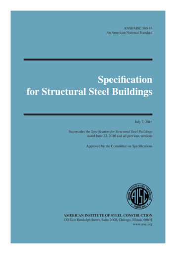
High Strength ConnectorsHIGH STRENGTHCONNECTOR TMi n n o va ve co m p o n e nt s fo r i n s p i re d d e s i g n nalb60 IN MSE AXRT . GIO UN SSLE in]pmax[in]j[in]HSC-4.00014 1/441071/21/29/165/819/32HSC-5.56319 1/165 9/161395/83/413/167/819/32HSC-6.62520 3/86 5/813117/811 1/161 1/825/32HSC-8.62527 1/88 5/8181411 1/41 5/161 3/87/8HSC-10.7525 5/810 3/416161 1/41 1/21 9/161 5/87/8HSC-12.7527 3/412 3/417191 1/41 3/41 13/161 7/87/81417191 1/21 3/41 13/161 7/87/8HSC-14.00* 29 3/4*Limited availability, inquire about lead ƟmesTypicalAssemblyAssemblyTypicalDe nes brace length in eldXtHSSHSS XX.XX ØZLHSS60 LmemberCAST CONNEXHIGH-STRENGTH CONNECTORHSC-XX.XXCJPEsƟmaƟng required length of HSS:LHSS Lmember - 2(Z X)X 2g 3(tHSS)When using these equaƟons to esƟmate the length of the HSS or Pipe required (LHSS)for a given element, note that the actual HSS or Pipe thickness (tHSS) can be signi cantlythinner than the nominal value. Refer to the relevant HSS or Pipe speci caƟon.Page 1 of 2Page 13PRINTEDON 20-07-2020PRINTED:09-19-2017g
i n n o va ve co m p o n e nt s fo r i n s p i re d d e s i g n sHIGH STRENGTHCONNECTOR vailableLoad and Resistance Factor Design (LRFD)Allowable Stress Design (ASD)The connector shown offers a factored strengthequal to the lesser of:a) LRFD values in the table below,b) factored strength of the bolted joint betweenthe connector and the gusset plate(see Cast Connex HSC Design Manual forpre-designed bolt pa erns), andc) the factored strength of gusset plate and itsassociated welded joints.The connector shown offers an allowable capacityequal to the lesser of:a) ASD values in the table below,b) allowable capacity of the bolted joint betweenthe connector and the gusset plate(see Cast Connex HSC Design Manual forpre-designed bolt pa erns), andc) the allowable capacity of gusset plate and itsassociated welded joints.LRFDφTn* φMn,op**[kips][k. ]ASDTn/Ω* Mn,op/Ω**[kips][k. ]HSC-4.000315167.3210111.3Iop 14.002560425017102830167.0Speci ed minimumyield strengthFy 50 ksiSpeci ed minimumtensile strengthFu 80 ksiNominal strengths have been determined using AISC 360-10.* Tn: Nominal tensile yielding strength:Equal to value determined from Chapter J4.The governing gross-sec on of the connector is Ag 2w·t Iop: Out-of-plane moment of iner aPage 14Page 2 of 2PRINTEDON 20-07-2020PRINTED: 09-19-2017**Mn,op: Nominal out-of-plane exural strength:Equal to value determined from Chapter F2.The governing plas c sec on modulus is Z w·t (t pmin)
www.castconnex.com
Nominal strengths have been determined using AISC 360-10. Pn: Nominal strength Equal to minimum strength of the connector, min. sized gusset, and pin using Sec ons D5.1, D2a, E3, J4.2 and J7a. Page 2 of 2 01-08-2020 SOLID PIN: D pin: Diameter of pin; diameter of pin hole not more than