Transcription
Angular Stable X-Plate and2-Hole PlateFor osteotomies, arthrodeses andfractures of the footSurgical Technique
Image intensifier controlThis description alone does not provide sufficient background for direct useof DePuy Synthes products. Instruction by a surgeon experienced in handlingthese products is highly recommended.Processing, Reprocessing, Care and MaintenanceFor general guidelines, function control and dismantling of multi-partinstruments, as well as processing guidelines for implants, please contactyour local sales representative or refer are-maintenanceFor general information about reprocessing, care and maintenance ofDePuy Synthes reusable devices, instrument trays and cases, as well asprocessing of DePuy Synthes non-sterile implants, please consult theImportant Information leaflet (SE 023827) or refer are-maintenance
Table of ContentsIntroductionAngular Stable X-Plate and 2-Hole Plate 2The AO Principles of Fracture Management 4Surgical TechniqueX-plate: Fixation of a Crescentic Osteotomy 5X-plate: 1st TMT Arthrodesis 92-Hole Plate: Fixation of an Akin Osteotomy 13Implant Removal 14Implants 15Ordering Information 16MRI Information 18 Notes Precautions WARNINGSAngular Stable X-Plate and 2-Hole Plate Surgical Technique1
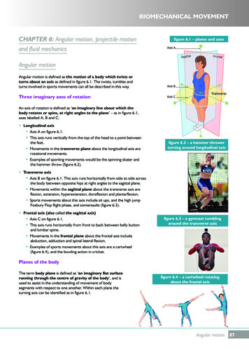
Angular Stable X-Plate and 2-Hole PlateFor osteotomies, arthrodeses and fractures of the footSystem descriptionThe X-plate and 2-hole plate have angled, threaded roundholes allowing insertion of 2.7 mm locking screws(head 2.4 mm) without the screw heads protruding.2Surgical Technique Angular Stable X-Plate and 2-Hole Plate
X-shape Arms can be bent for an adaptable screw pathCrescentic saw blade guided byKirschner wire P ositioning of the osteotomy and guidance of the sawusing a 1.6 mm Kirschner wireDeflection of two screw holesIntended Use, Indications and Contraindications can befound in the corresponding system Instructions for Use.Angular Stable X-Plate and 2-Hole Plate Surgical Technique3
The AO Principles of Fracture ManagementMissionThe AO’s mission is promoting excellence in patient careand outcomes in trauma and musculoskeletal disorders.AO Principles1,21.2.3.4.Fracture reduction andfixation to restoreanatomical relationships.Fracture fixation pro viding absolute or relativestability, as required by the “personality” ofthe fracture, the patient, and the injury.Preservation of theblood supply to soft- tissues and bone by g entle reduction techniques and carefulhandling.Early and safemobilization andrehabilitation of the injured partand the patient as awhole. Müller ME, M Allgöwer, R Schneider, H Willenegger. Manual of Internal Fixation. 3rd ed. Berlin, Heidelberg, New York: Springer. 1991 Buckley RE, Moran CG, Apivatthakakul T. AO Principles of Fracture Management: 3rd ed. Vol. 1: Principles, Vol. 2: Specific fractures. Thieme; 2017.124Surgical Technique Angular Stable X-Plate and 2-Hole Plate
Surgical TechniqueX-plate: Fixation of a Crescentic OsteotomyThis particular surgical technique is restricted to a crescentic o steotomy at the base of the 1st metatarsal fixedwith an X-plate. Preoperative planning, the distal soft tissue release, the removal of exotosis and the mobilization of sesamoid bone are to be assessed and performedat surgeon’s discretion.1. A pproach to and performance of theosteotomyIf the surgeon does not have the specific instrumentscited here, the crescentic osteotomy can also be performed with instruments of his or her choice.(a)Required instrumentsOscillating Saw Attachment II Crescentic Technique532.023Saw Blade 30 17.9 0.6 mm, crescentic,for Oscilliating Saws, sterile03.000.313SSaw Blade 30 21.9 0.6 mm, crescentic,for Oscilliating Saws, sterile03.000.316SThe metatarsal I base is approached through a 3–4 cmlong dorsal incision. Expose the extensor hallucis longusand the b revis tendons. Hold the latter medially or laterally to the side.Identify the metatarsal I/cuneiform I articular cavity with aKirschner wire or the image intensifier.At an angle as close as possible to 120 , insert a 1.6 mmKirschner wire into the sagittal plane that runs throughthe lengthwise axis of the 1st metatarsal. The distancebetween the osteotomy and the MTC joint should be1 cm. (a)(b)A neutral orientation in the mediolateral plane is desirable. Medial orientation of the Kirschner wire may lead to theele vation of the distal metatarsal fragment and pronationof the toe. Conversely, a lateral orientation of theKirschner wire may lead to the depression of the distalmetatarsal fragment and supination of the toe. (b)Insert the Colibri Power Tool with the oscillating saw attachment over the Kirschner wire. Keep a firm grip on thedrilling machine while performing the osteotomy. (c)(c)Angular Stable X-Plate and 2-Hole Plate Surgical Technique5
Surgical TechniqueX-plate: Fixation of a Crescentic Osteotomy2. Correct the intermetatarsal anglePosition both metatarsal fragments with two bone holdingforceps or two Kirschner wires by pressing the proximalfragment in a medial direction, and the distal fragment in alateral direction.Insert a Kirschner wire running from a medial-distal to aproximal direction to provide temporary fixation. Precaution:Do not elevate the distal metatarsal.6Surgical Technique Angular Stable X-Plate and 2-Hole Plate
3. Bend the X-plateRequired instrumentsBending Pin for LCP Plates 2.4 and 2.7, with thread329.922Universal Bending Pliers, length 167.5 mm391.963With the assistance of 2 bending pins or a forceps andone bending pin, adapt the X-plate to the anatomy. WARNING:Only a slight amount of bending is necessary. Repeatedlybending the plate causes material fatigue and must therefore be avoided.4. Predrill and fix the plateRequired instrumentsLCP Drill Sleeve 2.7 (head LCP 2.4), with Scale up to 60 mm323.061Drill Bit 2.0 mm, with double marking, length 140/115 mm323.062Depth Gauge for Screws 2.7 to 4.0 mm,measuring range up to 60 mm319.010Screwdriver Shaft Stardrive SD8, self-holding314.467Torque Limiter, 0.8 Nm, with AO/ASIF Quick Coupling511.776Handle with Quick Coupling311.430The first locking screw is inserted from a distal to proximal direction through the osteotomy. Note:The angle of the threaded holes identified with two dotsfacilitates insertion of locking screws through the osteo tomy.Screw the LCP drill guide into the plate hole. Predrill thehole with a 2.0 mm drill with a scale. Read the screwlength on the drill guide scale. Precaution:You must use the LCP drill guide for the drill hole andplate thread to be aligned on the same axis.Angular Stable X-Plate and 2-Hole Plate Surgical Technique7
Surgical TechniqueX-plate: Fixation of a Crescentic OsteotomyAlternatively, determine the screw length with the depthgauge.Introduce the measured length of the 2.7 mm lockingscrew (2.4 mm head). For the screw to lock properly,manually screw in the last threads using the 0.8 Nmtorque limiter.Insert the other locking screws in the same manner. Afterpre drilling, always first screw in the locking screw beforestarting on the next hole. Remove the Kirschner wire usedfor temporary fixation.8Surgical Technique Angular Stable X-Plate and 2-Hole Plate
Surgical TechniqueX-plate: 1st TMT ArthrodesisThe X-plate is for neutralization.1. Preparing the arthrodesisLocalize the 1st TMT joint with a Kirschner wire or anothermethod. The approach is through a dorsomedial incision.Prepare the joint surfaces for internal fixation.Temporarily fix the joint with a Kirschner wire or clamp.Angular Stable X-Plate and 2-Hole Plate Surgical Technique9
Surgical TechniqueX-plate: 1st TMT Arthrodesis2. CompressInsert a compression screw from a proximal to distal direction or visa versa. (Alternatives: from a plantar-distal toproximal-dorsal direction, or from a plantar-proximal to adistal-dorsal direction). Remove the temporary fixation.3. Bend the plateRequired instrumentsBending Pin for LCP Plates 2.4 and 2.7, with thread329.922Universal Bending Pliers, length 167.5 mm391.963With the assistance of 2 bending pins or a forceps andone bending pin, adapt the X-plate to the anatomy. WARNING:Only a slight amount of bending is necessary. Repeatedlybending the plate causes material fatigue and must therefore be avoided.10Surgical Technique Angular Stable X-Plate and 2-Hole Plate
4. Insert the locking screwsRequired instrumentsLCP Drill Sleeve 2.7 (head LCP 2.4), with Scale up to 60 mm323.061Drill Bit 2.0 mm, with double marking, length 140/115 mm323.062Depth Gauge for Screws 2.7 to 4.0 mm,measuring range up to 60 mm319.010Screwdriver Shaft Stardrive SD8, self-holding314.467Torque Limiter, 0.8 Nm, with AO/ASIF Quick Coupling511.776Handle with Quick Coupling311.430The locking screws can be inserted in any sequence.Screw the LCP drill guide into the plate hole. Predrill thehole with a 2.0 mm drill with a double marking. Read thescrew length on the drill guide scale.Alternatively, determine the screw length with the depthgauge.Angular Stable X-Plate and 2-Hole Plate Surgical Technique11
Surgical TechniqueX-plate: 1st TMT ArthrodesisIntroduce the measured length of the 2.7 mm lockingscrew (2.4 mm head). For the screw to lock properly,manually insert the last threads using the 0.8 Nm torquelimiter.Introduce the other locking screws in the same manner.After pre drilling, always first insert the locking screw before proceeding to the next hole.12Surgical Technique Angular Stable X-Plate and 2-Hole Plate
Surgical Technique2-Hole Plate: Fixation of an Akin OsteotomyPreoperative planning, the distal soft tissue release,the removal of exotosis and the mobilization of sesamoidbone are to be assessed and performed at surgeon’s discretion1. OsteotomyA medial incision is made. Perform the osteotomy.Retain the lateral cortex. Stabilize with a Kirschner wire ifnecessary. Precaution:If the lateral cortex is fractured, the osteotomy must bestabilized with a Kirschner wire.2. Affix the plateRequired instrumentsLCP Drill Sleeve 2.7 (head LCP 2.4), with Scale up to 60 mm323.061Drill bit 2.0 mm, with double marking, length 140/115 mm323.062Depth Gauge for Screws 2.7 to 4.0 mm,measuring range up to 60 mm319.010Screwdriver Shaft Stardrive SD8, self-holding314.467Torque Limiter, 0.8 Nm, with AO/ASIF Quick Coupling511.776Handle with Quick Coupling311.430In most cases, this plate does not have to be bent.Screw the LCP drill guide into the plate hole. Predrill thehole with a 2.0 mm drill with a scale. Read the screwlength on the drill guide scale. Alternatively, determine thescrew length with the depth gauge. Precaution:You must use the LCP drill guide for the drill hole andplate thread to be aligned on the same axis.Introduce the measured length of the 2.7 mm lockingscrew (2.4 mm head). For the screw to lock properly,manually insert the last threads using the 0.8 Nm torquelimiter.Use the same procedure for the second locking screw.Angular Stable X-Plate and 2-Hole Plate Surgical Technique13
Surgical Technique2-Hole Plate: Fixation of an Akin Osteotomy3. After internal fixationIf a Kirschner wire was used, remove it now. Note:If the lateral cortex is fractured, leave the Kirschner wirein place.Implant RemovalIn case the physician decides to remove the implants, implants can be removed by using general surgical instruments. In case of difficult removal circumstances, aScrew Extraction Set is available with corresponding instructions.14Surgical Technique Angular Stable X-Plate and 2-Hole Plate
ImplantsX-plate, pure titanium447.711* X-Locking Plate 2.4/2.7, x-small,2 214 mm, Pure Titanium447.702* X-Locking Plate 2.4/2.7, small,2 218 mm, Pure Titanium447.704* X-Locking Plate 2.4/2.7, medium,30 20 mm, Pure Titanium447.706* X-Locking Plate 2.4/2.7, large,36 20 mm, Pure TitaniumX-plate, stainless steel247.711* X-Locking Plate 2.4/2.7, x-small,22 14 mm, Steel247.702* X-Locking Plate 2.4/2.7, small,24 18 mm, Steel247.704* X-Locking Plate 2.4/2.7, medium,30 20 mm, Steel247.706* X-Locking Plate 2.4/2.7, large,36 20 mm, Steel2-hole plate447.710* Locking Plate 2.4/2.7, straight, 2 holes,17 6.0 1.6 mm, Pure Titanium247.710* Locking Plate 2.4/2.7, straight, 2 holes,17 6.0 1.6 mm, SteelLocking screws402.206–260* LCP Locking Screws Stardrive 2.7 mm(head 2.4 mm), self-tapping,length 6–60 mm, TAN202.206–260* LCP Locking Screws Stardrive 2.7 mm(head 2.4 mm), self-tapping,length 6–60 mm, Steel*Available sterile and non-sterileAngular Stable X-Plate and 2-Hole Plate Surgical Technique15
Ordering Information01.282.104 Compact Foot X-Locking Plate 2.4/2.7 andLocking Plate 2.4/2.7, straight (2 holes), Pure Titanium682.730 Module Compact Foot X-Lock. Plate 2.4/2.7 and Locking Plate2.4/2.7, straight (2 holes), with Lid, without Contents01.282.102 Compact Foot X-Locking Plate 2.4/2.7 andLocking Plate 2.4/2.7, straight (2 holes), Steel682.7301ImplantsModule Compact Foot X-Lock. Plate 2.4/2.7 and Locking Plate2.4/2.7, straight (2 holes), with Lid, without Contents 1Implants447.711* X-Locking Plate 2.4/2.7, x-small, 22 14 mm, Pure Titanium 2247.711* X-Locking Plate 2.4/2.7, x-small, 22 14 mm, Steel447.702*X-Locking Plate 2.4/2.7, small, 24 18 mm, Pure Titanium2247.702*X-Locking Plate 2.4/2.7, small, 24 18 mm, Steel2447.704*X-Locking Plate 2.4/2.7, medium, 30 20 mm, Pure Titanium2247.704*X-Locking Plate 2.4/2.7, medium, 30 20 mm, Steel2447.706*447.710*X-Locking Plate 2.4/2.7, large, 36 20 mm, Pure TitaniumLocking Plate 2.4/2.7, straight, 2 holes,17 6.0 1.6 mm, Pure Titanium 2247.706*247.710*X-Locking Plate 2.4/2.7, large, 36 20 mm, SteelLocking Plate 2.4/2.7, straight, 2 holes,17 6.0 1.6 mm, Steel26312.240Double Drill Guide 2.7/2.01329.922Bending Pin for LCP Plates 2.4 and 2.7, with thread2323.061 LCP Drill Sleeve 2.7 (head LCP 2.4), with Scale up to 60 mm,for Drill Bits 2.0 mm1310.8701323.062 Drill Bit 2.0 mm, with double marking, length 140/115 mm,3-flute, for Quick Coupling1314.4671Screwdriver Shaft, Stardrive, SD8, self-holding310.163 Drill Bit 2.0 mm, with marking, length 110/95 mm,2-flute, for Jacobs Chuck310.200 Drill Bit 2.0 mm, length 85/70 mm, 2-flute, for Jacobs Chuck310.260 Drill Bit 2.7 mm, length 100/75 mm, 2-flute, for Quick CouplingDrill Bit 2.7 mm, length 85/70 mm, 2-flute, for Jacobs Chuck310.280Drill Bit 2.7 mm, length 125/100 mm, 2-flute, for Quick Coupling310.534Drill Bit 2.0 mm, with marking, length 110/85 mm,2-flute, for Quick Coupling313.303Screwdriver Shaft, Stardrive, SD8, cylinder, with groove,shaft 3.5 mm, for Mini Quick Coupling313.304Screwdriver Shaft, Stardrive, SD8, cylinder, with groove,shaft 3.5 mm, for AO/ASIF Quick Coupling314.039Screwdriver Shaft, Stardrive, SD8, self-holding347.981Holding Forceps for Plates 1.0 to 2.4Add suffix “s” to the article number to order sterile product.16312.240Double Drill Guide 2.7/2.01329.922Bending Pin for LCP Plates 2.4 and 2.7, with thread2323.061LCP Drill Sleeve 2.7 (head LCP 2.4), with Scale up to 60 mm,for Drill Bits 2.0 mm1310.870Countersink 2.7, length 62 mm1323.062Drill Bit 2.0 mm, with double marking, length 140/115 mm,3-flute, for Quick Coupling1314.467Screwdriver Shaft, Stardrive, SD8, strumentsCountersink 2.7, length 62 mm2Surgical Technique Angular Stable X-Plate and 2-Hole Plate310.163Drill Bit 2.0 mm, with marking, length 110/95 mm,2-flute, for Jacobs Chuck310.200Drill Bit 2.0 mm, length 85/70 mm, 2-flute, for Jacobs Chuck310.260Drill Bit 2.7 mm, length 100/75 mm, 2-flute, for Quick Coupling310.270Drill Bit 2.7 mm, length 85/70 mm, 2-flute, for Jacobs Chuck310.280Drill Bit 2.7 mm, length 125/100 mm, 2-flute, for Quick Coupling310.534Drill Bit 2.0 mm, with marking, length 110/85 mm,2-flute, for Quick Coupling313.303Screwdriver Shaft, Stardrive, SD8, cylinder, with groove,shaft 3.5 mm, for Mini Quick Coupling313.304Screwdriver Shaft, Stardrive, SD8, cylinder, with groove,shaft 3.5 mm, for AO/ASIF Quick Coupling314.039Screwdriver Shaft, Stardrive, SD8, self-holding347.981Holding Forceps for Plates 1.0 to 2.4
01.282.004 LCP Compact Foot Basic Instrument Set and ScrewsØ 2.7 mm, Titanium01.282.002 LCP Compact Foot Basic Instrument Set and ScrewsØ 2.7 mm, Steel682.733Insert, size 1/2, Compact Foot Instruments (Basic Instrument Set)1682.733Insert, size 1/2, Compact Foot Instruments (Basic Instrument Set) 1391.962Bending/Cutting Pliers1391.962Bending/Cutting Pliers1391.963Universal Bending Pliers, length 167.5 mm2391.963Universal Bending Pliers, length 167.5 mm2319.005Depth Gauge for Screws Ø 2.0 and 2.4 mm,measuring range up to 40 mm319.0051Depth Gauge for Screws 2.0 and 2.4 mm,measuring range up to 40 mm1319.010Depth Gauge for Screws Ø 2.7 to 4.0 mm,measuring range up to 60 mm1319.010Depth Gauge for Screws Ø 2.7 to 4.0 mm,measuring range up to 60 mm1311.012Handle, medium, with Mini Quick Coupling1311.012Handle, medium, with Mini Quick Coupling1311.430Handle with Quick Coupling, length 110 mm1311.430Handle with Quick Coupling, length 110 mm1682.735Rack for LCP Locking Screws Ø 2.7 mm (head LCP 2.4)1682.735Rack for LCP Locking Screws Ø 2.7 mm (head LCP 2.4)1682.736Rack for Cortex Screws Ø 2.7 mm1682.736Rack for Cortex Screws Ø 2.7 mm1511.776Torque Limiter, 0.8 Nm, with AO/ASIF Quick Coupling1511.776Torque Limiter, 0.8 Nm, with AO/ASIF Quick Coupling1511.777Torque Limiter, 0.4 Nm, with AO/ASIF Quick Coupling1511.777Torque Limiter, 0.4 Nm, with AO/ASIF Quick Coupling1402.210–402.240LCP Locking Screw Stardrive Ø 2.7 mm (head LCP 2.4),self-tapping, length 10–40 mm, TAN3202.210–202.240LCP Locking Screw Stardrive Ø 2.7 mm (head LCP 2.4),self-tapping, length 10–40 mm, Steel3402.242–402.260LCP Locking Screw Stardrive Ø 2.7 mm (head LCP 2.4),self-tapping, length 42–60 mm, TAN2202.242–202.260LCP Locking Screw Stardrive Ø 2.7 mm (head LCP 2.4),self-tapping, length 42–60 mm, Steel2402.870–402.900Cortex Screw Stardrive Ø 2.7 mm, self-tapping,length 10–40 mm, TAN3202.870–202.900Cortex Screw Stardrive Ø 2.7 mm, self-tapping,length 10–40 mm, Steel3402.964–402.969Cortex Screw Stardrive Ø 2.7 mm, self-tapping,length 45–60 mm, TAN2202.964–202.969Cortex Screw Stardrive Ø 2.7 mm, self-tapping,length 45–60 mm, Steel2OptionalOptional313.300Combined Holding Sleeve forCortex Screws Stardrive Ø 2.4/2.7 mm, SD8313.300Combined Holding Sleeve forCortex Screws Stardrive Ø 2.4/2.7 mm, SD8313.301Holding Sleeve forLCP Screws Stardrive Ø 2.4/2.7 mm (head LCP 2.4), SD8313.301Holding Sleeve forLCP Screws Stardrive Ø 2.4/2.7 mm (head LCP 2.4), SD803.100.000 Handle, lockable, with Mini Quick Coupling03.100.000 Handle, lockable, with Mini Quick Coupling314.121X-ray symbol Stardrive Ø 50 mm, thickness 0.5 mm, steel314.121X-ray symbol Stardrive Ø 50 mm, thickness 0.5 mm, steel402.206LCP Locking Screw Stardrive Ø 2.7 mm (head LCP 2.4),self-tapping, length 6 mm, TAN202.206LCP Locking Screw Stardrive Ø 2.7 mm (head LCP 2.4),self-tapping, length 6 mm, Steel402.208LCP Locking Screw Stardrive Ø 2.7 mm (head LCP 2.4),self-tapping, length 8 mm, TAN202.208LCP Locking Screw Stardrive Ø 2.7 mm (head LCP 2.4),self-tapping, length 8 mm, SteelAccessories for the Colibri machine system (532.001)Vario Cases532.023Oscillating Saw Attachment II Crescentic Technique689.507Lid (stainless steel), size 1/1, for Vario Case03.000.313S Saw Blade 30 17.9 0.6 mm, crescentic,for Oscilliating Saws, sterile689.509Vario Case, Framing, size 1/1, height 67 mm689.516Vario Case, Framing, size 1/2, height 126 mm03.000.316S Saw Blade 30 21.9 0.6 mm, crescentic,for Oscilliating Saws, sterile689.537Lid (Stainless Steel), size 1/2, for Vario Case682.640Insert, size 1/4, for Additional InstrumentsVario Cases have space for:LCP Compact Foot Basic Instrument Set (Art. No. 01.282.004 or 01.282.002)3 Implant Modules 1 Insert, size 1/4,for Additional Instruments (Art. No. 682.640)LCP Compact Foot Basic Instrument Set (Art. No. 01.282.004 or 01.282.002) and4 implant modulesAngular Stable X-Plate and 2-Hole Plate Surgical Technique17
MRI InformationTorque, Displacement and Image Artifacts accordingto ASTM F2213, ASTM F2052 and ASTM F2119Non-clinical testing of worst case scenario in a 3 T MRI system did not reveal any relevant torque or displacementof the construct for an experimentally measured localspatial gradient of the magnetic field of 3.69 T/m. Thelargest image artifact extended approximately 169 mmfrom the construct when scanned using the GradientEcho (GE). Testing was conducted on a 3 T MRI system.Radio-Frequency-(RF-)induced heating accordingto ASTM F2182Non-clinical electromagnetic and thermal testing of worstcase scenario lead to peak temperature rise of 9.5 Cwith an average temperature rise of 6.6 C (1.5 T) and apeak temperature rise of 5.9 C (3 T) under MRI Conditions using RF Coils [whole body averaged specificabsorption rate (SAR) of 2 W/kg for 6 minutes (1.5 T) andfor 15 minutes (3 T)]. Precautions:The above mentioned test relies on non-clinical testing.The actual temperature rise in the patient will depend ona variety of factors beyond the SAR and time of RF application. Thus, it is recommended to pay particular attention to the following points: It is recommended to thoroughly monitor patientsundergoing MR scanning for perceived temperatureand/or pain sensations. Patients with impaired thermo regulation ortemperature sensation should be excluded from MRscanning procedures. Generally it is recommended to use a MR system withlow field strength in the presence of conductiveimplants. The employed specific absorption rate (SAR)should be reduced as far as possible. Using the ventilation system may further contribute to reduce temperature increase in the body.18Surgical Technique Angular Stable X-Plate and 2-Hole Plate
Not all products are currently available in all markets.This publication is not intended for distribution in the USAIntended use, Indications and Contraindications can be found in the corresponding system Instructions for Use.All Surgical Techniques are available as PDF files at www.depuysynthes.com/ifuSynthes GmbHEimattstrasse 34436 OberdorfSwitzerlandTel: 41 61 965 61 11www.depuysynthes.com DePuy Synthes Trauma, a division of Synthes GmbH. 2021. All rights reserved.SE 836416 AB (DSEM/TRM/1214/0240) EOS: 166807-211202 12/20210123
hole with a 2.0 mm drill with a scale. Read the screw length on the drill guide scale. Precaution: You must use the LCP drill guide for the drill hole and plate thread to be aligned on the same axis. Angular