Transcription
Architecting a software-defined data centerwith Big Cloud Fabric and Dell EMC ScaleIOA Dell EMC Deployment and Best Practices GuideDell EMC Networking Solutions EngineeringAugust 2017
RevisionsDateDescriptionAuthorsAugust 2017Initial release – Version 1.0Ed Blazek, Curtis Bunch, Dennis Dadey, Jordan WilsonTHIS WHITE PAPER IS FOR INFORMATIONAL PURPOSES ONLY AND MAY CONTAIN TYPOGRAPHICAL ERRORS AND TECHNICALINACCURACIES. THE CONTENT IS PROVIDED AS IS, WITHOUT EXPRESS OR IMPLIED WARRANTIES OF ANY KIND.Copyright 2017 Dell Inc. All rights reserved. Dell and the Dell EMC logo are trademarks of Dell Inc. in the United States and/or other jurisdictions. Allother marks and names mentioned herein may be trademarks of their respective companies.
Table of contents1Introduction .5Typographical Conventions .62Pod architectures .7Big Cloud Fabric pod .8VMware vSphere pod types .103Hardware .124Management network .165Deploy Big Cloud Fabric .18Big Cloud Fabric controller .19Big Switch Zero Touch Fabric .22Tenant and segment configuration .26VMware integration .296Deployment of VMware vSphere.35vCenter server deployment and design .36Virtual network design .397Deploying Dell EMC ScaleIO .44Deploy the Dell EMC ScaleIO plug-in.46Upload Dell EMC ScaleIO OVA Template .47Deploy Dell EMC ScaleIO .48Dell EMC ScaleIO GUI .518Performance Tuning .52Maximum Transmission Unit size .53Quality of Service.56Network I/O Control .59AConfiguration details .61BTechnical support and resources .62C3B.1Dell EMC product manuals and technical guides .62B.2Dell EMC Solution Briefs .62B.3Big Switch Networks product manuals and technical guides .62B.4VMware product manuals and technical guides .62Support and feedback .63Architecting a software-defined data center with Big Cloud Fabric and Dell EMC ScaleIO
Executive summaryThis document provides best practices and details how to deploy a software-defined data center (SDDC)powered by Dell EMC S-Series switches, Dell EMC PowerEdge servers, Big Switch Networks, VMwarevSphere, and Dell EMC ScaleIO. The goal of this document is to: 4Assist administrators in selecting the best hardware and topology for their Big Cloud Fabric networkDeliver detailed instructions and working examples on cabling, configuration, and deploying the BCFnetworkDeliver detailed instructions and working examples on deploying and configuring VMware vSpherecomponentsDeliver step-by-step instructions and working examples on deploying and configuring a sample DellScaleIO virtual SANShow conceptual, physical, and logical diagram examples for various networking topologiesArchitecting a software-defined data center with Big Cloud Fabric and Dell EMC ScaleIO
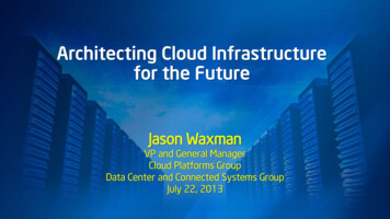
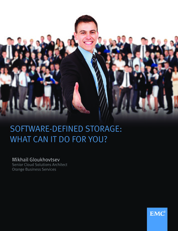
1IntroductionApplications are the engines for modern businesses. They drive innovation, operational efficiency, andrevenue generation. They demand an infrastructure that is highly agile and easy to manage while reducingcosts. These applications, which include mission critical Enterprise Resource Planning (ERP) systems, multitier web applications, and big data, have placed new constraints on the networking infrastructure; support forhigh east-west traffic bandwidth, virtual machine mobility, and multitenancy.Infrastructure teams have struggled to respond to these requirements. Unlike the rest of the portfolio theymanage, legacy networks remain highly static and require extensive manual intervention and operationaloverhead. While the speed, scale, and density of equipment offered by traditional networking vendors haveincreased over the last two decades, the underlying architectures and business operating models have stayedfundamentally unchanged.Dell EMC is working closely with Big Switch Networks to introduce the industry’s first data center leaf-spine IPfabric solution built using Dell EMC open networking switches and Big Cloud Fabric (BCF). This joint solutionapplies the hardware-software disaggregation enabled by Dell EMC and Big Switch Networks. SoftwareDefined Network (SDN) designs inspired by hyperscale data center architectures, provide significant costsavings and operational efficiencies for enterprise data centers by enabling the VMware centered softwaredefined data center (SDDC).With built-in integration for VMware, BCF is an ideal physical network for virtual environments, networkvirtualization, and hyper-converged Infrastructure (HCI). It is the industry’s first SDN-based fabric, using opennetworking switch hardware that provides intelligent, agile, and flexible networking for the VMware SDDC.With servers, networking, and virtualization in place, distributed storage remains as the final component of theSDDC model. Dell EMC ScaleIO is a perfect storage foundation for the SDDC. ScaleIO delivers scale-out,block storage using commodity hardware. ScaleIO creates a server-based Storage Area Network (SAN) builtfrom server direct-attached storage to deliver flexible and scalable performance on demand.Conceptual view of Big Cloud Fabric (BCF) and Dell EMC solution for VMware environment5Architecting a software-defined data center with Big Cloud Fabric and Dell EMC ScaleIO
Typographical conventionsThis document uses the following typographical conventions:6Monospaced textCommand Line Interface (CLI) examplesBold monospaced textCommands entered at the CLI promptItalic monospaced textVariables in CLI examplesBold textGUI navigation promptsArchitecting a software-defined data center with Big Cloud Fabric and Dell EMC ScaleIO
2Pod architecturesA pod is a combination of computing, network, and storage capacity, designed to be deployed as a singleunit. As a result, a pod is the largest unit of failure in the software-defined data center (SDDC). Carefullyengineered services ensure that each pod has little to no shared vulnerability between pods. While each podusually spans one rack, it is possible to aggregate multiple pods into a single rack or to span a pod acrossmultiple racks.There are two different types of pods used in this deployment sample: Big Cloud Fabric (BCF) pod – A pair of BCF controllers manages a maximum of 16 racks withredundant leaf switchesVMware vSphere pods – A collection of the ESXi hosts and virtual machines grouped by function Inthis document, three VMware pod types are defined: Management, ScaleIO/Compute, and EdgepodsThe maximum of 16 racks for the BCF rack is a limit imposed on the deployment covered in this paper. Thisnumber is reached due to 32 40GbE QSFP interface limit of the Dell EMC S6010-ON used as the spineswitch. BCF has a tested maximum of 128 racks. See Big Cloud Fabric Verified Scale Guide for moreinformation.Note: Big Switch documentation requires a customer account to access. Contact your Big Switch Networksaccount representative for assistance.7Architecting a software-defined data center with Big Cloud Fabric and Dell EMC ScaleIO
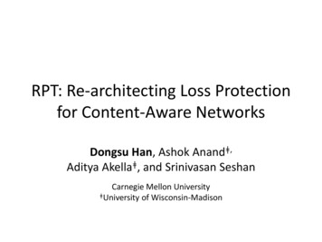
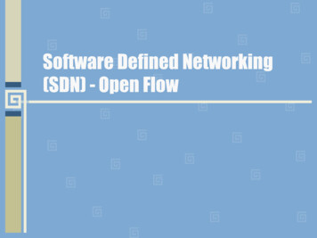
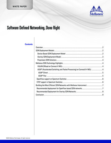
Big Cloud Fabric podIn this example, the Big Cloud Fabric (BCF) pod contains two spine switches and six redundant leaf switchesdistributed over three racks. Two BCF controller nodes are deployed in an active/standby configuration. TwoDell EMC Networking S6010-ON switches are deployed as spine switches and six Dell EMC NetworkingS4048-ON switches are servicing three server racks in a redundant configuration. The following image showsa final view of the leaf-spine network architecture used in this example as demonstrated by the BCFController graphical user interface (GUI):Leaf-Spine switched fabricThe leaf-spine architecture provides a simple and efficient design in response to challenges inherent in thehierarchical data center architecture. The 2-layer leaf-and-spine architecture optimizes bandwidth betweenswitch ports within the data center by creating a high-capacity fabric using multiple spine switches thatinterconnect the edge ports of each leaf switch. This design provides consistent latency and minimizes thehops between servers in different racks.The design lends itself well to the creation of an independent, replicable pod that scales without disruptingnetwork traffic. The addition of more leaf switches increases the number of switch edge ports for connectingto servers. Extra spine switches increase the fabric bandwidth and lower oversubscription ratios.Beyond physical parameters, there are two other considerations made in the BCF pod design: 8Oversubscription ratiosFault toleranceArchitecting a software-defined data center with Big Cloud Fabric and Dell EMC ScaleIO
In a leaf-spine network, oversubscription occurs at the leaf layer. Oversubscription is equal to the total amountof bandwidth available to all servers connected to a leaf switch divided by the amount of uplink bandwidth.Oversubscription total bandwidth / uplink bandwidthThe following image shows a typical Dell EMC ScaleIO node uses four 10GbE ports, two links going to eachleaf switch. If a rack has 19 nodes, each leaf provides a total bandwidth of 380Gbps. Each leaf switch wouldhave 80Gbps uplink bandwidth resulting in a 4.75:1 oversubscription ratio.Oversubscription calculations4.75 (oversubscription) 380 (total bandwidth) / 80 (uplink bandwidth)To decrease oversubscription ratios, more spine switches can be deployed. Using the same leaf/nodeconfiguration previously and increasing the number of spine switches to four the total uplink bandwidthdoubles to 160Gbps resulting in an oversubscription ratio of 2.4:1.2.4 (oversubscription) 380 (total bandwidth) / 160 (uplink bandwidth)In addition to decreasing the oversubscription ratio, extra spine switches improve the fabric resiliency. Forexample, if a spine switch fails, traffic continues across the remaining spine switches. The greater the numberof spine switches in the spine, the less additional load the remaining spine switches must take on in the eventof a failure in one spine switch. For example, with four spine switches, a failure of a single spine switch onlyreduces the capacity by 25% vs. a reduction in capacity of 50% with two spine switches.Tolerable oversubscription ratios vary by each enterprise organization and should be considered part of thedesign criteria. In this example, an oversubscription ratio of 4.75:1 is considered tolerable.9Architecting a software-defined data center with Big Cloud Fabric and Dell EMC ScaleIO
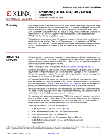
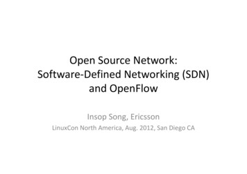
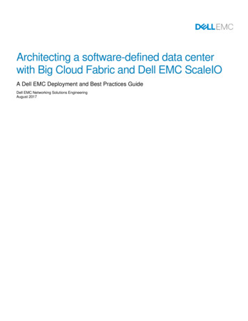
VMware vSphere pod typesA VMware pod can be one of three types that attaches to the Big Cloud Fabric (BCF). The VMware ValidatedDesigns Documentation defines the concept of the VMware pods. The VMware Validated DesignsDocumentation also contains numerous best practices for VMware vSphere deployment. The virtualizedenvironment in the following example contains three different pods: Management podScaleIO and Compute podEdge PodThe following image shows a physical layout with the three VMware pod types shown. In this example, theBCF pod is shown in the gray block and contains two BCF controller appliances, six leaf switches, and fourspine switches. The spine switches are shown in the right rack at the top with the two leaf switches directlybelow. The ScaleIO and Compute pod, shown in red, can be expanded to an extra 14 racks while beingincluded in the same BCF pod. The VMware vSphere management pod is shown in blue.10Architecting a software-defined data center with Big Cloud Fabric and Dell EMC ScaleIO
Big Cloud Fabric (BCF) and the VMware pod designThe Management pod runs the virtual machines and BCF Controller appliances that manage the entireenvironment. Management, monitoring, and infrastructure services that are virtual machines, are provisionedto a vSphere cluster, and provide high availability for these services. Permissions on the management clusterlimit access to administrators. This limitation protects these virtual machines and provides clear administrativeboundaries in the environment.The ScaleIO and Compute pod runs the required ScaleIO software components and hosts the tenant’svirtual machine workloads. The pod scales by adding more nodes, which increases computing and storagecapacity linearly.The Edge pod uses two leaf switches to route to the core of the data center. BCF is designed to easilyconnect to an existing Layer 3 device in the data center, such as a core router. Initially, the Edge pod consistsof a pair of leaf switches, shared by the Management pod. It can be expanded to include servers if a workloadrequires it. An example of the expansion would be for the deployment of VMware NSX Edge ServiceGateways (ESG), enabling VXLAN overlay networks.Note: Edge pod deployment is beyond the scope of this document. See VMware Validated DesignsDocumentation for instructions on deploying the Edge pod.11Architecting a software-defined data center with Big Cloud Fabric and Dell EMC ScaleIO
3HardwareThe three switch models that are listed, support the Open Network Install Environment (ONIE) and are on theBig Switch Networks hardware compatibility list. The six Dell EMC Networking S4048-ON switches aredeployed in three redundant leaf pairs across three racks, with the seventh deployed as an aggregationswitch for the management network. One Dell EMC Networking S3048-ON switch is deployed per rack andserves as an out-of-band access switch. The following table outlines the Dell EMC Networking switches usedin this example:Dell EMC Networking ONIE switchesSwitch modelSwitch port typesRolesCountDell EMC NetworkingS3048-ON48 x 1GbE BASE-T and 4x 10GbE SFP portsBCF switch control plane, BCF managementplane, PowerEdge iDRAC access3Dell EMC NetworkingS4048-ON48 x 10GbE SFP and 6 x40GbE QSPF portsLeaf switch, management networkaggregation7Dell EMC NetworkingS6010-ON32 ports of 40GbE QSPF portsSpine switch2The S3048-ON is a 1-Rack Unit (RU) switch with forty-eight 1GbE Base-T ports and four 10GbE SFP portsand deploys as an out-of-band switch.Note: The 24-port Dell EMC Networking S3024-ON is interchangeable with the S3048-ON and can be usedbased on switch port requirements.Dell EMC Networking S3048-ONThe S4048-ON is a 1-RU, multilayer switch with forty-eight 10GbE SFP ports and six 40GbE QSFP portsand deploys as leaf switches in the examples in this guide.Dell EMC Networking S4048-ONThe S6010-ON switch is a 1-RU, multilayer switch with thirty-two 40GbE QSFP ports and deploys as spineswitches.Dell EMC Networking S6010-ON12Architecting a software-defined data center with Big Cloud Fabric and Dell EMC ScaleIO
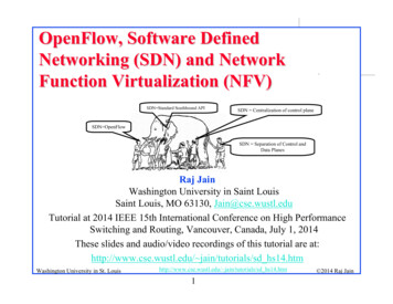
The Dell PowerEdge R630 hosts the Management and Edge pod workloads while the Dell PowerEdgeR730xd hosts the ScaleIO and Compute pod workloads. The BCF controllers were provided by Big SwitchNetworks as part of the BCF offering and are a part of the infrastructure requirements. The following tableshows the servers used, their function, and quantity:Dell EMC PowerEdge ServersServer modelFunctionCount Operating systemDell PowerEdge R630Management pod4ESXi 6.0 U3Dell PowerEdge R730xdScaleIO and compute pod4ESXi 6.0 U3Big Cloud Fabric (BCF) controllerBCF management2n/aShown are two of the four R630 servers, mgmt01esx01 and mgmt01esx04. ESX01 connects to Ethernet 1 onboth of the leaf switches, while ESX04 connects to Ethernet port 7. The port highlighted in red is thePowerEdge iDRAC interface and connects to the S3048-ON management switch. The IP fabric automaticallydefines the BCF MLAG when the BCF controller discovers the connection between the two leaf switches. Thefollowing image shows the interfaces provided by the R630 hardware, and the connections made to the leafswitches:Dell PowerEdge R630 interface connectionsThe following table provides a list of the interfaces provided by the R630 server:13Architecting a software-defined data center with Big Cloud Fabric and Dell EMC ScaleIO
Dell PowerEdge R630 interfacesPort setPortcount/typeColorFunctionConnection locationManagement 2 x 10GbEBlue/Green ESXi management traffic,VMware vSphere vMotiontrafficS4048-ON leaf switch pair forthe Management podiDRACRedPowerEdge iDRAC port onS3048-ON managementswitch1 x 1GbEOnboard controller for out-ofband (OOB) managementTwo of the possible
7 Architecting a software-defined data center with Big Cloud Fabric and Dell EMC ScaleIO 2 Pod architectures A pod is a combination of computing, network,