Transcription
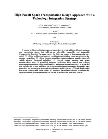
Automated approach to Register Design and Verification ofcomplex SOCBallori BanerjeeSubashini RajanSilpa NaiduLSI India R&D Pvt. LtdGTP, DevarabeesanahalliOuter Ring Rd, Bangalore, India( 91)80-41979520bbanerje@lsi.comLSI India R&D Pvt. LtdGTP, DevarabeesanahalliOuter Ring Rd, Bangalore, India( 91)80-41979614srajan@lsi.comLSI India R&D Pvt. LtdGTP, DevarabeesanahalliOuter Ring Rd, Bangalore, India( 91)80-41979603snc@lsi.comABSTRACTToday's designs contain several hundreds to thousands of registersand memory elements. Starting from documentation to designimplementation to verification of each single register, each bit and itsproperty involves a lot of time and complexity.Use of a single source, written in a high-level register and memorymodeling language like SystemRDL, for documentation, design andverification helps to reduce this complexity.The paper describes this methodology which provides an almostzero-time, low maintenance, and reusable register design andverification system. A complete solution from SystemRDL to RTLand documentation, to a complete reusable VMM based registerverification environment, the Register Abstraction Layer-RAL, isdiscussedThe paper presents useful RDL constructs for modeling scalableregister descriptions, like registers arrays, regfiles and register fieldinstantiation. Also presented are constructs for modeling standardregister types like interrupt enable and interrupt status register. A fewuseful field properties and their mapping to hardware implementationare discussed.Commercially available register automation tools can be used togenerate several outputs from SystemRDL input. This includesdocument, RTL, C headers, verification components and othercustom outputs which may be required. Challenges encounteredwhile setting up the flow with third party tools are discussed.An example comprising a set of read-write and status registers isprovided to help in understanding the transition of the input to theoutputs formats.HDL: High Level Description LanguageSoC: System on ChipRAL: Register Abstraction Layer, a VMM application packageRALGen: Synopsys tool to convert RDL to RALVMM: Verification Methodology Manual, by Synopsys1. INTRODUCTIONRegisters and memory elements constitute a large percentage oftoday’s large and complex designs. On-chip registers define thesoftware interface to the chip, and usually represent the largestportion of the chip specification or programmer's guide.Continuously increasing number of registers makes documentation,implementation and maintenance a growing challenge. Moreover,changing specifications during the design cycle require repeatedupdates to design, test bench, and register/memory test cases as alsoto documentation. Manually managing these components affectsproductivity and increases probability of introducing errors in theprocess.Most times, though, registers have a regular structure, defined bytheir field attributes. Using this characteristic, it is possible to definea flow where the register architecture is defined in a high levelregister description language like SystemRDL, which in turn is usedto generate the design, documentation and verification components.This helps to reduce the often tedious and error-prone task ofmanaging registers, and enables design, verification and firmwareteams to work more efficiently from consistent and synchronizedviews of the chip design.Once setup, the flow is repeatable and can be used across block,cluster (Sub chip-level) and chip level, with lot of reuse of code andenvironmentWe have implemented this flow on a multi-million gate SoC (around140 million gates) where on-chip registers are greater than 25,000overall! Having initially started with the manual coding of registersand later moving to the unified register management flow, thefollowing section illustrates the advantage in terms of effort savingachieved by adopting the methodology.Categories and Subject Descriptors2. LEGACY FLOW: NO AUTOMATION[Hardware Software Co-design]: Automatic Register modelingflow, language constructsRegister definition generally starts with an architect scoping out aspecification. Once the specification is completed the hardwareengineer, software engineer, and verification engineers can begincoding different views of the registers described in the functionalspecification. Once we have a design, verification and softwareengineers can start running tests. Anytime a bug is discovered thespecification must be changed and all the subsequent outputs must bechanged accordingly. But due to other priorities the designer wouldhave changed the code but not the document or vice versa. ThisGeneral TermsLanguage, Design, Verification.KeywordsCSR: Control and Status RegisterRDL: Register Description LanguageRTL: Register Transfer Language
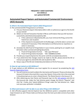
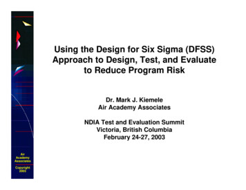
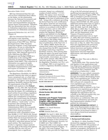
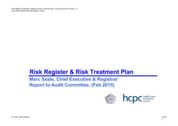
process repeats itself many times over the course of the project.Bugs are only one source of change though. Marketing requests mayalso come in at any stage of the design cycle requiring thespecification to change and all downstream code to be modified.Figure 1 captures this course in a flow chart.iv.high level verification environment code (HVL)This is shown in Figure 2. The RDL file serves as a one-stop pointfor any register update required following a requirement change.Register Description Language- SystemRDLRequirementChangeSpecification &65&RPSLOHUVerificationEnvironmentRTLRTLfor SynthesisValidationComponnetC Codefor FirmwarHHVL Codefor VerificationDriverDevelopmentVerify with signFigure 2: Automated Register DV FlowYesBug/enhancements?Bug ?Yes3.1.1 Choosing SystemRDLCoding the RTL with address decoding for 4000 registers, with fieldshaving different properties is a week’s effort by a designer.Developing a re-usable randomized verification environment withtests like reset value check, read-write is another 2 weeks, at theleast. Closure on bugs requires several feedbacks from verification toupdate design or document. So overall, there is at least a month’seffort plus maintenance overhead anytime the address mapping ismodified or a register updated/added.While evaluating the register modeling options for the flow,following items were considered:1. Ease of capture: To get various designers to agree to use alanguage standard other than a HDL for register modeling,it should be possible to capture the specifications in a userreadable and writable format.2. Comprehensive set of constructs: It should be possible todefine all types of registers that may be used in a design,for instance read-write, read-only, interrupt enable/mask,multiple instances of a register, a group of similar registers,external registers.3. Ease of usage: Defining various registers using theconstructs should be fairly straight-forward.4. Ease of maintenance/version control: This allows changecontrol.5. Support by vendors and stability of flow: We needed tocheck with third party vendors on how mature their toolsare to support a particular standard as an input.6. Implementation guidelines: If a standard has inbuiltimplementation guidelines it is easy to understand theoutput generated and allows portability.This flow is susceptible to errors where there could be disconnectbetween document, design, verification and software. The automatedregister design and verification (DV) flow streamlines this process.In this regard, SPIRIT IP XACT XML and SystemRDL standardswere considered. Also, possibility of an Excel spreadsheet forcapturing register definitions was explored.Adopting the automated flow, it took 2 days to write the RDL. Therest of components were generated from this source. A small amountof manual effort may be required for items like back-door pathdefinition, but it is minimal and a one-time effort.IP XACT is an XML format for capturing design components.However, SystemRDL provides a user readable and writable formatto succinctly capture the description from which rest of thedeliverables are produced. It has several constructs with particularimplementation guideline for different types of registers, like readwrite, read-only. Being a text file, it lends itself to easy editing andmaintenance using version control.NoHopefully Done !Figure 1: Legacy FlowAs an example, in a module that we are implementing, there are fourthousand registers. Translating into number of fields, for 4000 32-bitregisters we have 128,000 fields, with different hardware andsoftware properties!3. AUTOMATED REGISTER DESIGN ANDVERIFICATION FLOW3.1 MethodologyThe flow starts with the designer modeling the registers using a highlevel register description language, like SystemRDL. Third partytools are available to generate the various downstream componentsfrom the RDL file:i.RTL in Verilog/VHDLii.C/C code for firmwareiii.Documentation ( different formats)An Excel spreadsheet appears easy; however a standard format needsto be used for all IP blocks of a SOC, while having some method forversion control. There is no defined specification for RTLimplementation when registers are defined in a spreadsheet. Hencegenerated RTL is open to tool interpretation of spreadsheet registerattributes. It lacks a defined method for grouping similar registers orcreating an array of registers, where the basic register is defined onlyonce and we can specify the number of instances of it at defined
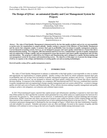
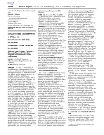
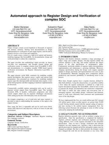
addresses. SystemRDL constructs are very efficient to capture suchrequirements.Thus we arrived at SystemRDL as a standard way of definingregisters for all blocks in our project.3.2 Extending flow for VMM based VerificationRegister Abstraction Layer, RAL is a VMM application packagewhich helps create an object oriented abstraction layer to modelregisters and memories in a design under test.A complete VMM compliant randomized, coverage driven registerverification environment can be created by extending the flow suchthat:i. Using 3rd party tool, from SystemRDL the verificationcomponent generated is RALF, Synopsys’ RegisterAbstraction Layer File.ii. RALF is passed through RALGEN, a Synopsys utilitywhich converts the RALF information to a complete VMMbased register verification environment. This includesautomatic generation of pre-defined tests like reset valuecheck of registers and functional coverage model, whichwould have taken considerable staff-days of effort to write.Figure 3 illustrates the Verification flow.StartAn example of a Control and Status register, CSR, modeled inSystemRDL is given in Table 1.Input RDL fileTable 1: SystemRDL for CSR Example (CSR EXAMPLE)// **** FIELDS ****field myControl {hw r;sw rw;fieldwidth 16;// The above combination would result in a flip-flop in CSR register.// The following would show up in generated document outputs//(HTML, etc.)desc "CSR example's 16 bit control field";reset 16'h3020;};Third Party Tool generatesRALF, DOC, RTLRalGen creates RAL modelfrom RALFRegister verification usingRAL model in environmentRegisterSpecificationChanged?SystemRDL is an object-oriented register description language(RDL).Its semantics support the entire life-cycle of registers fromspecification, model generation and design verification tomaintenance and documentation. Components are defined inSystemRDL using four basic types of defining elements:i.Fields – keyword field. This is the basic component thatusually maps to a flip-flop or wire/bus. A register’sindividual bit/bits are mapped to field.ii.Registers – keyword reg. A Register (reg ) has a set of oneor more field instances that are atomically accessible bysoftware at a given addressiii.Register files – keyword regfile. Describes a logicalgrouping of one or more register and register file instances.iv.Address Maps – keyword addrmap. Addressmap containsregisters, register files or other addressmaps and assigns anaddress, defining the boundary of an implementation.Each component relates to a number of properties which describes itspurpose and implementation.A field has four basic properties:i. fieldwidth : describes number of bits/bitii. reset: has the default/on-reset value.iii. hw: captures design’s ability to sample/update a fieldiv. sw: captures programmer’s ability to read/write a field.In addition to these four, software/hardware properties like rclr,woclr, hwclr can be added to model the corresponding behavior.Also, there are properties to add descriptive content that getsreflected in documentation: name; descYesNoRegisterVerification resultsStopFigure 3: Generating VMM based RAL model for Verification4. DEMONSTRATING WITH A CSREXAMPLE4.1 Source File: SystemRDL Descriptionfield myStatus {hw w;sw r;desc "CSR example's status field";};// **** REGS ****reg Control and Status reg {myControl control[15:0]; // bit position assignedmyStatus status[31:28]; // moves bit position to [31:28]// Thus bit[27:16] are now reservedstatus- reset 4'b1010; // reset value defined for status};// **** ADDRMAPS ****addrmap csr example {name "RDL Example for Control Status Register";desc "An example Addressmap.";Control and Status reg CSR @0x0020;reg {field { reset 32'hABCD BEEF;} myField[31:0];} myReg @0x0024;};
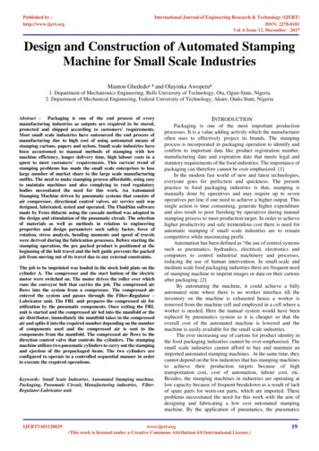
4.2 Output Component 1: RALFThe Synopsys Register verification file component, RALF, for theRDL CSR description (Table 1) is shown in Table 2.will allow some customization in the look and information content ofthe document .Document formats supported can vary from MicrosoftWord, RTF to HTML.Table 4: Document View for CSR EXAMPLETable 2: RALF for CSR EXAMPLEblock csr example {bytes 4;register CSR @0x20 {bytes 4;field CSR control (CSR control) @0 {bits 16;access rw;reset 0x3020;}field CSR status (CSR status) @28 {bits 4;access ro;reset 0xa;}}register myReg @0x24 {bytes 4;field myReg myField (myReg myField) @0 {bits 32;access rw;reset 0xabcdbeef;}}}4.3 Output Component 2: RTLUsing a third party tool to generate RTL will ensure standard RTLinterface for the registers, including read /write strobes and addressbus as inputs and the register fields as outputs. The RTL interfacecorres
RTL: Register Transfer Language HDL: High Level Description Language SoC: System on Chip RAL: Register Abstraction Layer, a VMM application package RALGen: Synopsys tool to convert RDL to RAL VMM: Verification Methodology Manual, by Synopsys 1. INTRODUCTION Registers and memory elements constitute a large percentage of