Transcription
Friction Stir WeldingHandbookEUROPEAN FRICTION STIR WELDING SPECIALIST ANDENGINEERFSW-TECH ERASMUS PROJECT www.fsw-tech.euProject E 2017-1-SK01-KA202-035415
Project E 2017-1-SK01-KA202-035415
Partnership to implement Project E Project E 2017-1-SK01-KA202-035415Associatia de Sudura din RomaniaEuropean Federation for Welding, Joining and CuttingInstituto de Soldadura e QualidadeVyskumny Ustav Zvaracsky - Priemyselny Institut SrInstitut za varilstvo d.o.o."The sole responsibility of this publication lies with the author. The European Union is notresponsible for any use that may be made of the information contained therein.“Project E 2017-1-SK01-KA202-035415
Project E 2017-1-SK01-KA202-035415
ContentsGlossary of Terms . 11.FSW Fundamentals . 3Introduction to FSW . 3FSW equipment . 15Welding processes . 21Parent Materials . 24References . 302.Joint Definition . 33Considerations for the Joint Design . 33Cleaning methods. 35Tools . 36Clamping . 38Backing Plates . 41Parent Materials . 42Equipment for FSW . 43FSW-Parameters . 45Jigs and Fixtures . 49Programs . 52References . 543.Supervision of the Welding Process Operation. 57Navigation Auxiliary Equipment . 57Hybrid welding methods (HFSW) . 60Problems Occurring in FSW . 63References . 654.Post Processing . 67Visual Inspection . 67Imperfections and Defects . 68Causes of imperfections/defects . 68References . 70i
5.Health & Safety . 71Health and Safety Plan (Safety regulations). 71General Health and Safety measures . 72Specific Health and Safety measures for FSW . 73Causes of Risks & Accidents. 74Measures to prevent or minimize risks . 75Risks associated to FSW and associated accidents . 75References . 766.Maintenance. 79Backing plate conditions. 79Tolerances for backing plate . 79Tool conditions . 80Tolerances for probe/pin/tool . 80Clamping/positioning devices conditions . 81Tolerances for clamping/positioning devices . 82References . 827.Quality . 83Destructive testing (DT) . 83Non-destructive testing . 88Acceptance criteria . 91Equipment Calibration. 97References . 988.Coordination . 99Standards for certification/qualification of welding personnel . 99Process constraints and limitations. 102Contract requirements typical items . 104Subcontracting activities. 104Work management principles . 105Manufacturing plan . 106References . 107FSW Handbook for Specialists & Engineersii
9.Designing of Parts . 111Types of Friction Stir Welds . 111Technical specifications for the final products . 115Guidance’s for Design in FSW . 116References . 12010. Designing of tools . 121Good practices for FSW tools development . 121Characteristic of the tool material . 124References . 12911. Implementation the FSW system . 131FSW Costs . 131References . 15012. Case Studies . 153Case study number 1: Autoclave fixtures. 153Case study number 2: Vibration test tables . 153Case study number 3: Crack repairs. 154Case study number 4: Underground vehicles . 154Case study number 5: Solar panels . 155Case study number 6: Naval shipbuilding panels . 156References . 159FSW Handbook for Specialists & Engineersiii
FSW Handbook for Specialists & Engineersiv
ForewordFriction Stir Welding Handbook is an educational material dedicated tothe training of the personnel involved in this welding process. It containsthe main information that will be able to offer specific knowledge andcompetences to the personnel who is involved in the qualificationprocess as a Friction Stir Welding Specialist and Engineer.The book is the result of an intellectual output of the project E 2017-1SK01-KA202-035415 Harmonized Friction Stir Welding TechnologyTraining across Europe project cofinanced by the European Commissionthrough ERASMUS program, and it can be used as teaching or learningsupport.The chapters of the book were elaborated by the members of theconsortium which implemented the project. Chapters 1 to 8 arecommon to both, the Specialist and Engineer, and are the following:Chapter 1: FSW FundamentalsChapter 2: Joint DefinitionChapter 3: Supervision of Welding Process OperationChapter 4: Post ProcessingChapter 5: Health and SafetyChapter 6: MaintenanceChapter 7: QualityChapter 8: CoordinationChapter 9: Designing of partsFrom chapter 1 to 8, the text in blue is dedicated to the EFSW-E only, theknowledge within that information is not included in the EFSW-Sguideline. Chapters 10 to 11 are dedicated to the Engineer Profile:Chapter 10: Designing of ToolsChapter 11: ImplementationChapter 12: Case Studies.I
FSW Handbook for Specialists & EngineersII
Glossary of TermsAdvancing side of weld - the side of the weld where the direction of toolrotation is the same as the direction of welding.Anvil - the structure supporting the root side of the joint.Axial force - force applied to the work piece along the axis of tool rotation.Bobbin tool - an FSW tool with two shoulders separated by a fixed length oran adjustable length pin. The self-reacting bobbin tool allows the shouldersto automatically maintain contact with the workpiece.Direction of tool rotation - the rotation as viewed from the spindle that isrotating the tool.Dwell time at end of weld - the time interval after travel has stopped butbefore the rotating tool has begun to withdraw from the weld.Dwell time at start of weld - the time interval between when the rotating toolreaches its maximum depth in the parent material and the start of travel.Entrance block - a sacrificial piece of metal that is secured to the beginningof a FSW joint, and provides filler material as the tool enters the edge of aworkpiece.Exit block - a sacrificial piece of metal that is secured to the end of a FSWjoint, and by providing filler material, eliminates an exit hole in the weldment.The exit hole will be relocated to the exit block.Faying surface - the surface of one component which is intended to be incontact with, or in close proximity to the surface of another component toform a joint.Fixed pin - a fixed length pin protruding from the shoulder and the pin'srotation is the same as the shoulder during welding.Flash - material expelled along the weld toe during FSW.Force control - method to maintain the required force on the tool duringwelding.Heel - part of the tool shoulder that is at the rear of the tool relative to itsforward motion.Heel plunge depth - distance the heel extends into the workpiece.Hook - faying surface that curves upward or downward along the side of theweld metal in a friction stir welded lap joint.Hole plug - a piece of filler metal which has been machined to allow itsinsertion into a hole and will be joined to the structure by FSW.Lateral offset - the distance from the tool axis to the faying surface.Multiple spindles – a friction stir welding system with two or more spindles.Pin - part of the welding tool that extends into the workpiece to make theweld.Position control - a method to maintain the required position of the tool duringwelding.Retreating side of weld - side of the weld where the direction of tool rotationis opposite to the welding direction.Self-reacting tool - a tool with two shoulders separated by a fixed lengthprobe or an adjustable-length probe.1
Shoulder - the portion of the tool contacting the surface of the parentmaterial during welding.Single spindle - a friction stir welding system with one spindle.Side tilt angle - the angle between the tool's axis and an axis normal to thebase material surface, measured in a plane perpendicular to the weld path.Stirred zone - the oval shaped region in the center of the weld, where a finegrained, equated microstructure exists.Tilt angle - the angle between the tool's axis and a plane perpendicular tothe weld path, when viewed perpendicular to the weld path.Thermo-mechanically affected zone (TMAZ) - the area of weld joint that hasbeen plastically deformed by the tool and has also had its microstructure andproperties altered by the heat of a welding process.Tool (friction stir welding) - a FSW tool is the rotating component consist of theshoulder and pin. As base material thickness is increased, the shoulderdiameter and pin length are also increased. Various pin designs include, butare not limited to, threaded, scrolled, fluted, or smooth. Pins may also haveadjustable length and, with a special spindle, counter-rotating. A tool usuallyhas a shoulder and a pin, but a tool may have more than one shoulder ormore than one pin. Also, a tool may not have a shoulder or a pin.Tool rotation speed - angular speed of the welding tool in revolutions perminute.Travel speed - rate at which the welding operation progresses in the directionof weldingDifference between advancing and retreating side – Courtesy of [1-6]Welding (including FSW) related terminologyComplex weld joint - a continuous weld joint with variations in sectionthickness and/or tapered thickness transitioning.Heat affected zone (HAZ) - the area of weld joint which has had itsmicrostructure and properties altered by the heat of a welding process.Multi-run welding - welding in which the weld is made in more than one run.Plasticity - the softening of metal material before it reaches its melting point.The mechanism usually becomes dominant at temperatures greater thanapproximately one third of the absolute melting temperature.Single run welding - welding in which the weld is made in one run [1-14].FSW Handbook for Specialists & Engineers2
1.FSW FundamentalsFriction stir welding is a material joining process where two or more metalworkpieces are joined by the friction heating and mixing of material in theplastic state caused by a rotating tool that traverses along the weld. FSW isconsidered to be the most significant development in metal joining in a decade.The friction stir welding machine is operated by a competent FSW operator whoperforms fully mechanized or automatic friction stir welding. The weldingspecialist have necessary skills and technical knowledge to plan, execute,supervise and test welding operations within a limited technical field involvingsimple welded constructions. A welding engineer is a type of materials engineer,who acquired an in-depth knowledge of the all aspects of welding that lead tothe manufacture of a product.The following modules main objective to give an overview of the FSW process.It starts with basic information’s about FSW and terminology, followed byadvantages and disadvantages of this process, characterisation of weldingequipment and tools. At the end of module, general concerns about weldabilityof different base materials are described.Introduction to FSWInvention and History of FSWFriction stir welding is classified as a one of the solid-state weldingtechniques. It was invented and patented in 1991 by The WeldingInstitute (TWI) of the United Kingdom for butt and lap joining of ferrous,non-ferrous metals and plastics. It was initially applied to aluminiumalloys, because of benefits, such as less sensitivity to contaminations, lessdistortion and improved strength and fatigue properties, compared tofusion welding. Implementation of FSW has occurred in industries such asautomotive, aerospace, railway and maritime. It is being usedincreasingly to weld materials, which are traditionally considered to benot weldable, for example aluminium alloys 2XXX and 7XXX. Furtherstudies aiming at widening the set of materials applicable for friction stirwelding, which include Mg-, Cu-, Ti-, Al-alloy matrix composites, lead,stainless steels, thermoplastics and dissimilar materials [1-1, 1-2, 1-3, 1-4].The development of lightweight construction, materials, and design playimportant role in economy and fuel consumption. Road, railway, waterand air transport is based on the use of aluminium and its alloys, becauseof economic and ecological reason. The MIG and TIG welding processesare characterized by high heat input, occurrence of problems ofthermal deformation and formation of aluminium oxide. Rivetedassemblies are more expensive to make, have more weight than weldedassemblies and holes required to insert rivets cause stress concentration.Another problem related to riveted assemblies is that they are not tightand leak proof. The introduction of FSW solved these problems.Friction Stir Spot Welding (FSSW) was first developed at the Mazda MotorCorporation and Kawasaki Heavy Industry, respectively. This new spotwelding technique is intended to replace other joining techniquesinclude resistance spot welding, self-piercing rivets and clinching. FSSWFSW Handbook for Specialists & Engineers3
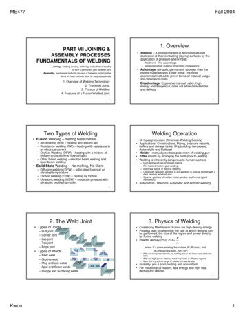
is primarily intended for joining Al alloys, to reduce cost of consumablesusing during assembly manufacturing (self-piercing rivets) or in the caseof resistance spot welding, reduce the electricity consumption and costof electrode dressing due to physical properties of aluminium. Mazda RX8 rear door panels were manufactured using FSSW in 2003 and Mazdaclaimed 99% reduced energy consumption comparing to conventionalearlier process. The process consists of only the plunge and retract phaseand it can be described as pure spot FSW.Development of friction stir spot welding is to be further developed andimproved and nowadays it can be classified in three categories: Purespot FSSW; Refill FSSW and Swing FSSW.Refill FSSW solves the problem of presence of keyhole (exit hole) due toretraction of the tool at the end of the weld, in the middle of the joint.Exit hole occurring in conventional friction stir spot welding and it isavoided in refill FSSW, which can also be used as a repair process. Theforming of fully consolidated weld is possible because the welded regionis produced in a process similar to a back extrusion. Swing FSSW is a thirdvariation of FSSW. This process produces a spot that is elliptical in shape.In comparison to the perfect circle obtained during conventional spotFSSW, elongated spot offers larger area of contact and this results inhigher joint strength [1-1].Fundamentals of FSWThe FSW process starts with a machine initiating rotation of a friction stirtool. A non-consumable pin and shoulder is plunged into the joint linebetween two rigidly clamped materials on a backing plate support.During plunge phase, the tool and the workpiece are at ambienttemperature, except the region surrounding tool and workpieceinterface.Rate of temperature rise, and extent of plasticity depends on the rate ofinsertion. The plunge phase is finished when the tool shoulder is in contactwith the substrate. Local heat via friction and plastic deformation iscreated, which softens the material to be welded. The tool shoulderproduce more heat than the pin surface. However, the deformation isgenerated by rotation of the tool pin which leads to the generation ofadditional heat. At this stage, force starts to drop as the metallicworkpiece reaches critical temperature for plastic flow. When weldingmetals with higher melting points, it is possible that the rotating tool canbe intentionally held in this position for a pre-determined time, known ashold time (also called dwell time), so as to reach the desiredtemperature needed for plastic flow.When plunge reach the selected plunge depth, the FSW machine startsthe traverse of the friction stir tool along the weld path. The rotation ofthe tool is maintained, geometric features on the shoulder and probedisplacing and mixing (stirring) material along the weld joint. The toolshoulder restricts metal flow to a level equivalent to it position, i.e. closeto the initial workpiece top surface. When the friction stir tool reaches theend of the path, it is retracted from the joint. This is the actual weldingphase and, depending on the type of FSW machine, can be controlledby displacement, force, power, torque, temperature etc. [1-1, 1-2, 1-4,1-5].FSW Handbook for Specialists & Engineers4
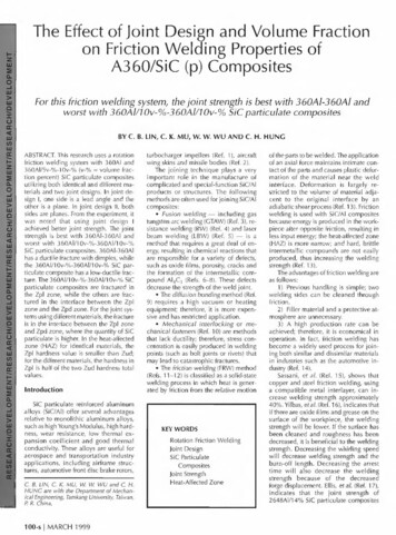
Figure 1-1: FSW process flowchart – Courtesy of [1-6]Friction stir processingFriction stir processing use similar working principle to FSW and it is knownas the surface modification technique. It can be used to improvemechanical and tribological characteristics. The difference betweenFSW and FSP is that they do have different purposes in practicalapplications. In FSW process the goal is to join two plates together,however, the FSP aims at modifying the microstructure of singlecomponent.As a result of obtained plastic deformation, which refines themicrostructure of a material, is improving mechanical properties ofmaterial. This process does not change the shape and size of the basematerial. It can be carried out selectively on a part for specific propertyenhancement, without affecting the properties in the rest of thematerial. In comparison to FSW, the pin of the FSP tool is often shorterthan the thickness of the sheet.Friction stir processing can also incorporate second phase particles intoa material to process composites and produce surface compositelayers. It can be done by inserting the powder (for example ceramicpowder) in the processing zone by creating the groove, pouring thepowder into it and then FSP.The FSP can be also used to eliminate casting defects and homogenizingthe as-cast microstructure in cast alloys. FSP can improve strength andductility of the cast alloy by breaking the dendritic microstructure [1-5, 17].FSW Handbook for Specialists & Engineers5
Figure 1-2: Friction Stir Welding (left) and Friction Stir Processing (right) - Courtesyof [1-8, 1-9] Heat distributionHeat generated in FSW process is combination of friction and plasticdissipation during deformation of the metal. Heat generation process issensitive to factors such as weld parameters, thermal conductivities ofthe workpiece, pin tool and backing anvil, and the weld tool geometry.The temperature field around the pin tool is asymmetric. FSW ofaluminium alloys shows higher temperatures on the retreating side. Thiscorrelates with tensile test failures, which occur predominantly in theheat affected zone. Majority of the heat generation occurs at theshoulder/workpiece interface, but the heat generated between thepint tool and the workpiece should be also included in defining theheat field. The amount of heat input from deformational heatingaround the pin tool is in range from 2% to 20%.Mechanisms of heat generation between the shoulder/workpiece andpin/workpiece interface are due to friction or plastic dissipation,depending on whether slide or stick conditions dominate at theinterface. The weld tools can consist geometric features, whichinfluence whether the two surfaces slide, stick, or alternate betweenthe two modes.As the temperature of the weld metal rises during FSW, the metalsoftens, torque is reducing, and less heat is distributed to the metal bymechanical work. A temperature-regulating mechanism can beobserved, which tends to stabilize the temperature and avoid meltingthe metal. Alternating the conditions at the interface between stickand slide lead to control of process temperature. If metal cools belowa critical temperature, where the deformational flow stress rises abovethe frictional slip stress, the interaction between the weld tool andworkpiece may change from deformational to frictional. If slide occursbetween the weld tool/workpiece interface, the heat input coulddecrease and reduce the temperature of the material. Alternatingboundary conditions at the interface can cause stick-slide oscillations[1-1]. Material stirringThermally softened, plasticized zone is a region bounded by the toolshoulder, anvil, and parent material. Weld parameters, pin tool designand materials are variables, which control volume of metal heated. Aportion of the heat is then swept by the mechanical working portion ofthe process.FSW Handbook for Specialists & Engineers6
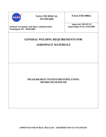
The thermally softened material is transported around the tool in thedirection of rotation. It is deposited in the form of bands, which can beviewed in the plan section of an FSW. The spacing of the bands areequivalent to the longitudinal distance the weld tool travels during asingle rotation. Geometric and microstructural differences within therefined weld nugget are caused by asymmetrical flow process thatoccur around the weld centreline. The metal flow can be describedusing either Nunes Kinematic Model or Arbegast Metalworking model[1-1]. Microstructural featuresIn the joint material four visually distinct microstructural zones can bedistinguished.Unaffected parent (base) materialThis zone is located furthest from the weld, which has the samemicrostructure and mechanical properties as it had before the FSWprocess. In this zone there are possible temperature variations, but theyare not enough to modify the microstructure and/or mechanicalproperties. The interface between the stir zone and base material isrelatively diffused and smooth on the retreating side of the tool, while itis quite sharp on the advancing side.Heat affected zone (HAZ)Moving towards the weld centre, we will find heat affected zone. In thiszone microstructure and mechanical properties are affected by theheat generated by FSW process, while there is no plastic deformation.Thermo-mechanically affected zone (TMAZ)The TMAZ undergone mechanical deformation the material in TMAZ isplastically deformed and the process is comparable to hot-working ofmetallic material. TMAZ zone is often defined to be withoutrecrystallization. This is true for aluminium, which is one of the mostcommonly applied materials in friction stir welding, but other materialscan experience recrystallization in this zone. These materials includetitanium and its alloys, austenitic stainless steel and copper. There is agenerally a distinct boundary between weld nugget and TMAZ.Stir zone (SZ) or weld nuggetStir zone is the region, where intense plastic deformation and frictionalheating during the FSW process, lead to recrystallized fine-grainedmicrostructure. This zone was previously occupied by the tool pin. Theterm stir zone is often-used term in friction stir processing, in which largevolumes of material are processed.Central nugget contain fine, equiaxed grains and displays layers ofvarying thickness, like “onion rings” (also known as the “metallurgicalband”). This macroscopically noticeable repetitive pattern on thetransverse and lateral section of the weld is unique feature occurringduring FSW and related processes.As the result, fine grain microstructure offers excellent mechanicalproperties, fatigue properties, enhanced formability and exceptionalsuper plasticity [1-3, 1-5, 1-1].FSW Handbook for Specialists & Engineers7
Figure 1-3: (a) Micrograph illustrating different zones in a friction stir weldedaluminium alloy. (b) Retreating side. (c) Advancing side – Courtesy of [1-1] Weld zone phenomenaThe weld nugget is bounded by the two adjacent zones – HAZ andthermomechanical affected zone. The size of the nugget depends ongenerated heat. Hotter welds are reported to have a larger nuggetthan colder welds. The onion ring pattern is not always apparent in theweld macrostructure. Patterns are more likely visible in colder weldsthan in hotter welds. The origin of the onion ring structure has not beenfirmly established yet.Generation of the onion structure can be explained as follows. Layered(onion) structure has been observed in the surface layers of ductilemetals in sliding. The structure is generated during successive shear ofthin layers when shear stress from friction force exceeds the yieldstrength of the material. The sliding is realized between the base metaland plunged FSW tool. An assumption can be made that theinteraction in this case if od adhesion nature, because a substantialamount of metal becomes involved in the plastic flow and aluminiumsticks to the instrument during welding. The deformation incompatibilitybetween the weld metal and the adjacent base material results information of such a structure in FSW. Deformation incompat
process as a Friction Stir Welding Specialist and Engineer. The book is the result of an intellectual output of the project E 2017-1-SK01-KA202-035415 Harmonized Friction Stir Welding Technology Training across Europe project cofinanced by the European Commission through ERASMUS program, and it can be used as teaching or learning support.