Transcription
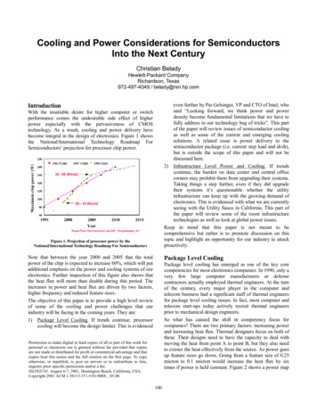
Cooling and Power Considerations for SemiconductorsInto the Next CenturyChristian BeladyHewlett-Packard CompanyRichardson, Texas972-497-4049 / belady@rsn.hp.comeven further by Pat Gelsinger, VP and CTO of Intel, whosaid “Looking forward, we think power and powerdensity become fundamental limitations that we have tofully address in our technology bag of tricks”. This partof the paper will review issues of semiconductor coolingas well as some of the current and emerging coolingsolutions. A related issue is power delivery to thesemiconductor package (i.e. current step load and di/dt),but is outside the scope of this paper and will not bediscussed here.2) Infrastructure Level Power and Cooling. If trendscontinue, the burden on data center and central officeowners may prohibit them from upgrading their systems.Taking things a step further, even if they did upgradetheir systems it’s questionable whether the utilityinfrastructure can keep up with the growing demand ofelectronics. This is evidenced with what we are currentlyseeing with the Utility fiasco in California. This part ofthe paper will review some of the room infrastructuretechnologies as well as look at global power issues.Keep in mind that this paper is not meant to becomprehensive but rather is to promote discussion on thistopic and highlight an opportunity for our industry to attackproactively.IntroductionWith the insatiable desire for higher computer or switchperformance comes the undesirable side effect of higherpower especially with the pervasiveness of CMOStechnology. As a result, cooling and power delivery havebecome integral in the design of electronics. Figure 1 showsthe National/International Technology Roadmap ForSemiconductors’ projection for processor chip power.Figure 1. Projection of processor power by theNational/International Technology Roadmap For SemiconductorsNote that between the year 2000 and 2005 that the totalpower of the chip is expected to increase 60%, which will putadditional emphasis on the power and cooling systems of ourelectronics. Further inspection of this figure also shows thatthe heat flux will more than double during this period. Theincreases in power and heat flux are driven by two factors,higher frequency and reduced feature sizes.The objective of this paper is to provide a high level reviewof some of the cooling and power challenges that ourindustry will be facing in the coming years. They are:1) Package Level Cooling. If trends continue, processorcooling will become the design limiter. This is evidencedPackage Level CoolingPackage level cooling has emerged as one of the key corecompetencies for most electronics companies. In 1990, only avery few large computer manufacturers or defensecontractors actually employed thermal engineers. At the turnof the century, every major player in the computer andtelecom business had a significant staff of thermal engineersfor package level cooling issues. In fact, most computer andtelecom start-ups today actively recruit thermal engineersprior to mechanical design engineers.So what has caused the shift in competency focus forcompanies? There are two primary factors: increasing powerand increasing heat flux. Thermal designers focus on both ofthese. Their designs need to have the capacity to deal withmoving the heat from point A to point B, but they also needto extract the heat effectively from the source. As power goesup feature sizes go down. Going from a feature size of 0.25micron to 0.1 micron would increase the heat flux by sixtimes if power is held constant. Figure 2 shows a power mapPermission to make digital or hard copies of all or part of this work forpersonal or classroom use is granted without fee provided that copiesare not made or distributed for profit or commercial advantage and thatcopies bear this notice and the full citation on the first page. To copyotherwise, or republish, to post on servers or to redistribute to lists,requires prior specific permission and/or a fee.ISLPED’01, August 6-7, 2001, Huntington Beach, California, USA.Copyright 2001 ACM 1-58113-371-5/01/0008 5.00.100
So this brings us to one of the key problems, heat fluxes aregoing up faster than interface material and die attachimprovements. There are countless companies who are tryingto come out with the miracle material such as conductivegreases, epoxies, phase change materials and pads to solvethis problem. None of these have provided majorbreakthroughs to keep pace with shrinking feature sizes.There have been some promising studies in the past such asthe work by Dolbear [1] in the area of metal pastes whichprovide an order of magnitude improvement in interfaceperformance but have many issues at this point that need tobe resolved before they can be commercialized.(Figure 2a) of a typical processor die with its accompanyingtemperature distribution (Figure2b). Note that only a quarterof the die is actually dissipating almost all of the power. Thisis a result of the fact that ¾ of the die is actually on-chipcache. Typically, in these situations, heat spreaders such asdiamond and copper have been used on the die to lowergradients.Package Cooling TechnologiesThere is number of techniques used for coolingsemiconductor packages that have become quite widespreadin the industry. But as with everything else, the coolingdemands of semiconductors are forcing the need for moreaggressive solutions.Figure 2a. Processor die power map (Courtesy J. Deeney)Figure 2b. Processor temperature distribution (Courtesy J. Deeney)Figure 4. Various heat sink technologies.Interface IssuesAs a result of this high heat flux, die-attach and interfacetechniques have been an area of significant attention. Figure3 shows a typical high performance processor package.The most common cooling technique is the use of heat sinks asshown in Figure 4. These devices are typically attached to thepackage lid or directly to the die. Their primary purpose is toincrease the area for heat rejection to the air. In the figure all ofthe heat sinks are considered passive except for the center fansink, which is considered an active heat sink. These examplesshow heat sinks that were produced using various techniquessuch as brazed copper folded fin (lower left), bonded fin(leftmiddle), machined (upper left), skived (upper middle), coldforged (upper right) and extruded (lower right). A moredetailed survey was completed by Chu et al [2].Still another common technique that has emerged in the pastdecade is the use of heat pipes. Their primary purpose is toaid in the transport heat from the source to the sink. Heatpipes are hollow vessels that contain a small amount ofworking fluid such as water with a wicking structure. Figure5 shows an illustration of how a heat pipe works. The fluidevaporates at the heat source and the vapor travels up thecenter of the pipe and condenses at the sink. The condensedfluid wicks back to the evaporator. Since this cycle takesFigure 3. Typical high performance processor package.Heat flows from the die through the die attach layer, into thelid, through another interface such as grease, into an aircooled or liquid cooled heat sink. The silver epoxy die attachdrives the thermal performance of the package.101
advantage of latent heat, the operating temperature isvirtually uniform along the pipe and thus, effectively creatingan infinite conductor. Figure 6 shows various applications ofthe use of heat pipes. The heat pipe to the left is a tube in finheat pipe while the heat pipe to the right is an embedded heatpipe both of which where used in HP’s V-Class servers. Theheat pipe in the top center is a tower heat pipe used inConvex’s C3 server with a sectioned sample just below. Atthe bottom center of the figure is a typical laptop heatpipe/spreader plate.resolved such as pump reliability, cost, weight and the hazardof leaks.Figure 7. Liquid cooled boards.Figure 5. Heat pipe illustration [3].In the late 1990s, refrigeration of semiconductors gainedsome popularity and found its way into some products suchas IBM’s S/390, DEC’s AlphaStation 600/800 andKryoTech’s K6 PC [4]. In these systems, refrigeration hasbeen used as an active thermal management system to moveheat from point A to point B and also to refrigerate thesemiconductor below ambient temperatures to improveperformance of the processor. Figure 8 shows how frequencycan be increased as a function of processor temperature. It isobvious that the performance benefits for sub-coolingprocessors can be huge but there are concerns as well. First,condensation is a catastrophic problem that requiresmeticulous evaporator insulation design. In addition, reliablecompressors are bulky. Figure 9 shows an example of apositive displacement vapor-cycle refrigerated PC. Note thatfor this type of system, the primary components are thecondenser, compressor, insulated evaporator (KryoCavity)and accumulator (not shown).Figure 6. Heat pipe examples.Although heat sink and heat pipe technology has allowedconventional air-cooled techniques for system thermalmanagement, it becomes obvious that if power trendscontinue more aggressive cooling techniques will berequired. There are many promising technologies emergingbut the most promising in the near term are liquid cooling,refrigeration and spray cooling.Although liquid cooling has been used in the past inmainframe computing until the early 90s, liquid coolingdisappeared with the adoption of CMOS. Figure 7 shows anexample of a liquid cooled system. Typically, these systemsare made up of five major components, a pump, a coldplate, aheat exchanger, pipes and depending on the design, anexpansion tank. Note that the example in the figure has fivecoldplates. The advantage of liquid is that water, forexample, it has about 5300 times the heat capacity of air for agiven volume with 1 to 2 orders of magnitude higher heattransfer coefficients. This allows significantly more compactcooling solutions. But there are issues that need to beFigure 8. Frequency improvement as a function of temperature(courtesy of KryoTech)102
designs are available as well. This technique is not asefficient as the vapor phase approach. Figure 11 shows anexample of such a cooler.technique that takes advantage of the latent heat ofevaporation by spraying Flourocarbons directly on the chipor the board. Thus far, almost all of the applications havebeen in government-funded programs but is on the verge ofbeing commercialized. The advantages are huge if one couldresolve some of the material compatibility issues that arebeing tested by current projects. Some key advantages are theability to have uniform temperature surfaces throughout thesystem as well a elimination of interfaces by evaporating offof the back side of the die. Figure 12 shows an illustration onhow spray cooling works. Figure 13 shows some earlyprototype multi-chip modules as well as the fan/pumpassembly.Figure 9. PC with vapor-cycle refrigeration system (courtesy ofKryoTech)All of the systems above use positive displacement pumpsbut there are a variety of other approaches such as acousticcompressors that vibrate a tuned cavity to create a standingway in the vessel as shown in Figure 10. This shows promisebecause there are no moving parts and thus, reliability shouldbe excellent though there are noise and vibration issues. Stillanother interesting refrigeration technique is the use ofthermoelectric coolers, which are solid state heat pumps thathave no moving parts and operate at low pressure. Figure 11shows a liquid to liquid thermoelectric cooler but liquid to airFigure 12. How spray cooling works (courtesy of Isothermal SystemsResearch)Figure 10. Cross section of acoustic compressor (courtesy ofMacroSonix)TECLiquid to LiquidChillerFigure 13. Prototype spray cooling units (courtesy of Isothermal SystemsResearch)Figure 11. Thermoelectric refrigerator (courtesy of ThermoTek)103
System 3 (lower middle in Figure 15) have been used inmany of the Data Centers in the Continental US. These haveworked very well in the under 100 W/ft2 but have had somelimitations in the above 100/ft2. For this reason many newtechnologies have been emerging to address the climbingheat loads in the data center. In the lower right corner ofFigure 15 is a novel approach by ENP called the “backpack”.It is essentially a liquid cooled heat exchanger that cools theexhaust air on the back of the rack so that air leaving the rackis cooled back down to ambient. The advantage of thisapproach is that condensation is not an issue and the aircooling is distributed throughout the data center. This willincrease the capacity of the data center although capacityvalues were not available at the time of this report. In thelower left corner of Figure 15 is an M&I Column Fan with acapacity of 300 W/ft2. This approach still uses under floorcooling which has certain limitations and thus, needs to beevaluated further. The top left image in Figure 15 shows theENP DataCool system. This innovative ENP system wasdeveloped for HP and was tested at HP in a 500ft2 prototypelab of know server heat loads. The testing demonstrated anunprecedented 500W/ft2 of capacity and is currently the onlytechnology known by this author that can handle that level ofheat load. The upper right corner shows how the DataCoolsystem is implemented. Note that this is a localizedoverhead-cooling scheme that blows down on computers andsucks up the waste heat. This approach solves many of theproblems associated with the under floor cooling. Some ofthose issues are: flow distribution/capacity, under floor cableblockage and air flow capacity of tiles/grates. As a final note,with densities as high as they are, liquid cooled data centerswith liquid cooled computers may be revisited once again.So the big picture question is how much power does a highend data center use? If one looks at some of the large InternetService providers, it is not uncommon to see data centers thatare as large as 100,000 ft2 to 200,000 ft2. If one does the mathand trends continue, a 200,000 ft2 data center within the next5 years could require 100 Megawatts of power. To support100 Megawatts of power a minimum of 60 Megawatts ofpower would be needed for the supporting mechanical roomfor a total of 160MW. This is 16% of the output of a typicalnuclear power plant. This in itself is a scary proposition butthere are other things to consider. First, the electricity costwould be over 100 million per year. Second, theapproximate usage of water in the cooling towers would beabout 10 million gallons per week, which may be asignificant resource issue in some area of the country.So, are we surprised about the power shortages in California?Figure 16 shows the demand and supply of electricity in theU.S. It should be no surprise to see the difference betweenthe two diminishing. It is speculated that the reason for this isthat nobody expected the increase in power caused by theInternet age and compounded by the fact that nobody wanteda power plant in their back yard.Figure 14. Heat-Density Trends in Data Processing, Computer Systems,and Telecommunications Equipment [5]Infrastructure Level Power and CoolingUltimately, all of this heat that is generated by the chips doesimpact the electronics system but even worse has directimpact on our ultimate customers who are owners of largedata centers such as banks, internet service providers andgovernment labs. In 1998, HP completed a study on datacenter capacity including all of the major manufacturerscurrent generation servers. The findings showed that mostdata centers had a capacity of 40 to 70 Watts/ft2 but at thattime the industry was shipping computers that ultimatelywould require capacities of 75 to 225 W/ft2 and projectionsshowed that in the next 5 years 500 W/ft2 capacity will berequired. At the time this was alarming because the industryas a whole was not aware of this disconnect. Since then thishas become a major issue and a group of manufacturersdeveloped a projection of power for the next decade[5].Figure 14 shows the projections of the collaboratingmanufacturers, which included Amdahl, Cisco, Compaq,Cray, Dell, EMC, Hewlett-Packard, IBM, Intel, Lucent,Motorola, Nokia, Nortel, Sun and Unisys.Figure 15. Data center cooling schemes [Clockwise from upper left]:ENP (Emerson Network Power) DataCool, ENP DataCool over headcooling scheme, ENP “Backpack”, ENP System 3, M&I Column Fan.Traditionally data centers have used CRAC (Computer RoomAir Conditioning) with air distributed under the floor.Typically, systems like Emerson Network Power’s (ENP)104
ConclusionWith semiconductor power increasing rapidly, there is nodoubt that package level cooling issues are importantengineering problems to solve. Some of these techniqueswere discussed here. Similarly, examples of emerging datacenter solutions demonstrate the engineering community’sability to solve problems at all levels.But there is a looming problem ahead of us With NorthAmerica using 30% of the world’s power for 8% of thepopulation; it becomes clear that as the rest of the world joinsthe digital economy, the energy demands will acceleraterapidly. Either we let our fate determine its own course or weproactively attack the power issues that we will face. It isobvious that the opportunities in the next century will be inpower management and efficiency.let’s make it happen!Figure 16. US Electrical and Supply Trends(Courtesy of R. Schmidt)There has been a lot of debate on what percentage of theelectrical supply computers and the internet consume.Kawamoto[6] estimated that in 1999 2% of the grid was usedby the industry but the Wall Street Journal[7] estimated 13%in 1999. ITI’s projection in Figure 17 corroborates with thelatter. Why the difference? The possible reason, Kawamotoonly includes power at the plug while the others also includethe burden on the power grid and cooling infrastructure. Thekey thing to note is not the number but the trend, which isgrowing rapidly.References1.2.3.4.5.6.7.Figure 17. Computer growth and electricity demand(Courtesy of R. Schmidt)105Dolbear, T., “Liquid Metal Pastes For Thermal Connections,”Proceedings of IEPS International Electronics PackagingConference, p. 475, Austin, 1992Chu, H., C. Patel, C. Belady, “A Survey of High-Performance,High Aspect Ratio, Air Cooled Heat Sinks,” Proceedings ofIMAPS International Systems Packaging Symposium, p.71,San Diego, 1999Holman, J.P., “Heat Transfer,” McGraw-Hill Inc., FifthEdition, New York, 1981ClieNT Server NEWS Flash, Issue Number 222.1 News Flash,G-2 Computer Intelligence Inc.,New York, October 20-24 1997“Heat-Density Trends in Data Processing, Computer Systems,and Telecommunications Equipment,” The Uptime rs/tuiheat1.0.htmlKawamoto, K., J. Koomey,. B. Nordman, R. Brown, M. Piette,A. Meier , “Electricity Used by Office Equipment and NetworkEquipment in the U.S.”, ACEEE Summer Study Conference onEnergy Efficiency in Buildings, Asilomar, CA, August 2000“Got a Computer? More Power to You,” Wall Street Journal,September 7, 2000.
aid in the transport heat from the source to the sink. Heat pipes are hollow vessels that contain a small amount of working fluid such as water with a wicking structure. Figure 5 shows an illustration of how a heat pipe works. The fluid evaporates at the heat source and the vapor tra