Transcription
O-ARMS AND MOBILE CTSCANNERSRADIATION SAFETY, REGULATORYISSUES, OPERATIONAL CHALLENGES,AND TIPSNathan Busse, MS, DABR DABSNMMedical Physicist, Denver HealthAssistant Professor,University of Colorado School of Medicine
Outline Regulatory ambiguitiesO-arms Fluoro testing, CBCT characteristics, radiationscatter, and operational recommendations CBCT dosimetry challengesMobile CTs System characteristics, image quality, radiationscatter Special applicationsFuture of mobile 3D imagingThings in red may be useful later
Disclaimer This talk will obviously discuss somespecific models of equipment Content should not be interpreted asendorsement; these are simply themodels I have the most experience with
What’s the difference: CT, CBCT, Fluoro? Boundaries are blurring; no clear definitionAsk your favorite regulator!CRCPD (2017) stated:CBCT machine is one that utilizes a divergentx-ray beam with a conical or pyramidal shape,a flat panel detector, and can generatethree-dimensional imagesCRCPD Publication: E-17-6, Technical White Paper: Cone Beam ComputedTomography (CBCT) For Dental Applications, H-44 Task Force (2017).
O-arm If you haven’t seen on yet you will soon Most commonly used in spinal surgerybut also neurosurgery, ortho, andtrauma applications Common worfklow: One spin (i.e. CBCT acquistion) at the startof the case Fluoro during hardware placement Second spin to verify hardware locationbefore closing
O-arm 40 cm x 30 cm, 2k x1.5k amphorous silicondetector0.6 / 1.2 mm focalspots12:1 grid96.5 cm bore diameterPower assisted drive at2 miles per hour!!!Medtronic O-arm User ManualBI-500-00095 Rev 3
O-arm Setup geometry and distances
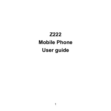
O-arm – Fluoro Can be operated withaccordion baffles open orclosed System must be‘undocked’ to operate Tube represented bysmall laser indicator,receptor indicated bylarge laser indicator Setup for measuringentrance exposure rates
O-arm – Fluoro Can be operated withaccordion baffles open orclosed System must be‘undocked’ to operate Tube represented bysmall laser indicator,receptor indicated bylarge laser indicator Setup for measuringentrance exposure rates
O-arm – Fluoro Good news: It’s like ac-arm but simpler! No mag modes, nosingle shotexposures Three fluoro modes: Low Level Normal High Level (Boost)
O-arm – Fluoro Good news: It’s like ac-arm but simpler! No mag modes, nosingle shotexposures Three fluoro modes: Low Level Normal High Level (Boost)
O-arm – Fluoro ExposureRates Typical exposure rates with either aluminumor PMMA Relatively similar to typical c-armsNormal Mode TechniqueR/min at 30 cm from receptorAttenuatorkVpmANormalHigh Level (Boost)1.9 cm Al558.40.912.193.8 cm Al679.21.363.98Al Pb12413.48.0418.15PMMA measurements Courtesy Cristina Dodge
O-arm – Fluoro IQ Poor high contrastresolution (no magmode) typically 16-24lp/in Good low contrastresolution, but beware ofghosting!
O-arm – X-ray fieldalignment
O-arm – X-ray fieldalignment Lead plate on a stick! (Or use maxmanual technique)
O-arm - Monitor Monitor may be adjusted using built-in SMPTEThis monitor will be used forguidance/interpretationMedtronic O-arm User ManualBI-500-00095 Rev 3
Internal Calibrations System will warn you if calibrations are morethan 30 days old. These can be easilyperformed by a physicist, but message can alsobe bypassedFirst step for IQ issues
O-arm – CBCT OperationalCharacteristics Beam width atisocenter 16.7 cm Fan angle 20 degrees Imaging volume 15 cmhigh x 20 cm diameterO-arm Technical Guide
O-arm – CBCT IQ CT Number Accuracyand Uniformityunpredictable Spatial Resolutionroughly equivalent toMDCTCourtesy Cristina Dodge
O-arm – IQ vs. CT Generally similar MTF and limiting resolutionO-arm has worse low contrast resolution that is notimproved with increasing slice thicknessCTO-armZhang et al.
O-arm – Radiation Scatter 120 kVp, 320 mAs Exposures in mRWhy do we have staff stepout of the room? Scatter equivalent to 64slice CT scanner!My recommendation: If staff must remain inroom they should bedoubly protected.Either In gantry shadow withlead apron on or Behind leaded glasswith lead apron on(anesthesia, etc)Zhang et al.
O-arm – Patient Dose Spinal implant placement patients randomly assigned C-arm orO-arm. Same surgeon for eachO-arm used two spins (pre and post hardware placement) - staff stepout of room during spinTLD measurements in field and out of fieldPatient dose higher usingnavigation (O-arm) thanwith fluoroscopyBratschitsch et al.
O-arm – Staff Dose Staff dose lower with O-arm, biggest differencefor surgeonBratschitsch et al.
O-arm – Dosimetry System reportsCTDIvol and DLP forspinsCTDI can bemeasured, butproblems arise from16.7 cm beamMedtronic O-arm User ManualBI-500-00095 Rev 3
CBCT DosimetryChallenges Main dosimetry challenge with CBCT is longitudinalextent of beam is broader than 10 cm pencil ionchamber We’re not measuring all the primary radiation, letalone all the scatterBuckley et al., Geleijns et al., Hernsdorf et al., Zhang et al.
CBCT Dosimetry OptionsAsk our therapy colleagues! This is thesame problem they face in measuringimaging dose for kV CBCT. They use avariety of methods. CTDI TG-111 Methodology Longer phantom, point dose TG-200 (Jan 2020) implementation IAEA Report 5 (2011) Increment pencil chamber CBDI Details on next slideBakalyar et al., IAEA Report 5
Cone Beam Dose Index For most cone beams, apencil ion chamber doesn’tcapture the entire primarybeam (n x T), much less thescatter CBDI replaces nT in thedenominator of the CTDIequation with the chamberlength By measuring at center and periphery, onecan calculate CBDIwThis represents the average dose acrossthe central 100 mm of the cone beamBuckley et al.
Now on to Mobile CT!
Ceretom Mobile CT Released 2006800 lbs32 cm bore, 25 cm FOV100, 120, 140 kVp1-7 mA in increments of 12, 4, 6 Timing “resolution” (rotationtime) 1.25, 2.5, 5, 10 mm slice thickness Pitch 1 or 1.5 Covers laminated with 0.5 mm Pb
Ceretom Daily QC
Ceretom IQ High contrast resolution: 7 lp/cm (about the same asfixed diagnostic scanners)CT Numbers checked with daily QCUsing ACR phantom, CT numbers typically passexcept for boneMy typical results below:MaterialAirCT Number AccuracyDensity(g/cm3) Ct # (HU) Acceptable Range0Polyethylene 1078.5850970FailUniformityProtocol Head 0.7LeftMaximumDifference-2.01.7Rumboldt et al.
Pop quiz: Ceretom or FixedCT?Rumboldt et al.
AnswerCeretomFixedRumboldt et al.
Pop quiz: Ceretom or FixedCT?Rumboldt et al.
AnswerFixedCeretomRumboldt et al.
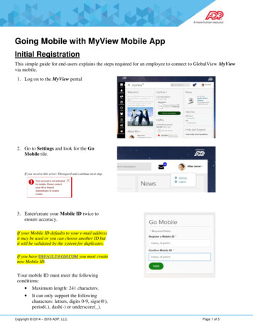
Ceretom Radiation Scatter 120 kVp, 7 mA, 2 s rot, 41.26 mGySingle axial scan, 16 cm head phantom – typicalprotocol would be 5-10 axial scans or equivalentLudlum 9DPDistance from isocenter: scatter (µR) / rotation1m: 199Ceretom1m: 192Patient Stretcher1m: 241m: 2530.5m: 161.3m: 781.2m: 141.3m: 21.5m: 83
Ceretom Radiation Scatter 120 kVp, 7 mA, 2 s rot, 41.26 mGySingle axial scan, 16 cm head phantom – typicalprotocol would be 5-10 axial scans or equivalentLudlum 9DPDistance from isocenter: scatter (µR) / rotation1m: 199Ceretom1m: 192Patient Stretcher1m: 241m: 2530.5m: 161.3m: 781.5m: 831.2m: 141.3m: 2Staff that mustremain in theroom shouldstand here andwear lead
Ceretom Radiation ScatterCaveat: Ceretom lead drapes eitheravailable or included Drapes not present at sites I’vevisited but now I know to ask Data from other mobile CTsuggests dose reductions couldbe substantial, especially on thebackside
Omnitom Released 20171700 lbs40 cm bore, 31.4 cm FOV70, 80, 100, 120 kVp5-45 mA in increments of 51, 2 rotation timeSlice thickness 0.625, 1.25, 2.5, 5, 10mmCovers laminated with 0.5 mm Pb,additional lead drapes includedAEC specified by Noise Level, min mA,max mA; MARIR recon with noise reduction, windmillartifact reduction, etc
Omnitom Controlled by tablet – no second towerto roll
Omnitom – Radiation Beam Width,Table Travel Nominal beam width 10 mm Measured beam width 13 mm
Omnitom – RadiationScatterCounter weight tokeep 16 cm headphantom (behinddrapes) from fallingoverLudlum 9DPPressurizedIon Chamber0.5 mm LeadEquivalentDrapes
Omnitom – RadiationScatter Leaded accordion screen (unknownthickness) on other side
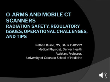
Omnitom RadiationScatter120 kVp, 35 mA, 2 s rot, 59.22 mGy Single axial scan, 16 cm head phantom – typicalprotocol would be 5-10 axial scans or equivalentLudlum 9DPDistance from isocenter: scatter µR / rotationwithout and with lead accessoriesLead DrapesLead Accordion1m: 1200/84Patient Stretcher1.5m: 239/191.5m: 7/70.5m: 6/61m: 13/92m: 26/151.5m: 8/61.5m: 149/26
Omnitom RadiationScatter1.5m: 149/26 Comparison with Omnitombrochure scatter, same technique1m: 1200/841.5m: 7/7Lead Accordion0.5m: 6/61.5m: 8/61m: 13/9Lead DrapesPatient Stretcher2m: 26/151.5m: 239/19Omnitom Brochure 1-NL5000-100rev00.
Bodytom – Brief Summary 85 cm bore, 60 cm FOV32 row / 20 mm beam, up to 300 mAMuch higher radiation scatterBodytom 1-NL4000-108 rev00.
Special Case: Mobile Stroke Units Reduce time to scan / tPA Initial European model in 2009featured shielded booth foroperator First US unit 2014 UTHSC inHouston As of 2018, roughly 20 in thecountry Lots of different implementations Most common: Ceretom scannermounted within an upgradedambulanceGutierrez et al.
Special Case: Mobile Stroke Units Over one year this unitscanned 106 patients inHouston In a few cases, nurse orvascular neurologistremained in ambulance withlead aprons on Otherwise staff exitedambulance Single CT tech operator hadan annual dose of 1.14 mSv Dose to CTtechnologist per scanis 0.01 mSv (1 mrem)Gutierrez et al.
Special Case: Mobile Stroke Units Caveat: Other implementationsuse larger CT scanners and mayhave substantially differentscatter For example, Northwestern’sfull-size 16-slice SiemensSomatom Shielded booth and technologistwearing lead apron backwards tocover their behind
Regulatory ChallengesCRCPD Suggested State Regulations forControl of Radiation Part F (2015) F.3.a.xi Portable or mobile x-ray equipmentshall be used only for examinations where itis impractical to transfer the patient to astationary x-ray installation F.6.k.iii(2) Mobile and portable systemsused continuously for greater than oneweek in the same location must meetcontrol booth requirements
Future of Mobile 3DImagingThe following are my opinions Increasing utilization pressure from Spinal, Neuro, and Ortho for intra-operativeguidance ICU to avoid transport Critical access hospitals seekingcost-savings
Future of Mobile 3DImaging Mobile CT has a role, but we must beadvocates for safety Know the proposed machine Scatter can vary tremendously with model Is the image quality sufficient for the task?
References Bakalyar D., et al. Report No. 200 – The Design and Use of the ICRU/AAPM CT Radiation DosimetryPhatom: An Implementation of AAPM Report 111 (2020).Bratschitsch, G., Leitner, L., Stücklschweiger, G. et al. Radiation Exposure of Patient and OperatingRoom Personnel by Fluoroscopy and Navigation during Spinal Surgery. Sci Rep 9, 17652 (2019).Buckley JG, Wilkinson D, Malaroda A, and Metcalfe P (2017) Investigation of the radiation dose fromcone-beam CT for image-guided radiotherapy: A comparison of methodologies J Appl Clin MedPhys. 176-80.CRCPD Publication: E-17-6, Technical White Paper: Cone Beam Computed Tomography (CBCT) ForDental Applications, H-44 Task Force (2017).Geleijns, Jacob & Salvadó, Marçal & Bruin, Paul & Mather, Richard & Muramatsu, Yoshihisa &McNitt-Gray, Michael. (2008). Dose Descriptors and Dose Assessment for a 320-slice Volume CTScanner.Gutierrez, JM et al., Radiation Monitoring Results from the First Year of Operation of a UniqueAmbulance-based Computed Tomography Unit for Improved Diagnosis and Treatment of StrokePatients. Health Physics 2016; 110: S73-S80.IAEA Human Health Reports No. 5, Status of Computed Tomography Dosimetry for Wide Cone BeamScanners, Vienna, 2011.Lars Herrnsdorf, Marcus Söderberg, "A method to characterize the radiation output from a cone beamO-arm using a device for dose and dose profile scanning measurement," Proc. SPIE 8668, MedicalImaging 2013: Physics of Medical Imaging, 86682Q (6 March 2013).Rumboldt Z, Huda W, All JW (2009) Review of portable CT with assessment of a dedicated head CTscanner. AJNR Am J Neuroradiol 30:1630–1636.Zhang, Jie & Weir, Victor & Fajardo, Liliosa & Lin, Jingying & Hsiung, Hsiang & Ritenour, Elston.(2009). Dosimetric characterization of a cone-beam O-arm (TM) imaging system. Journal of X-rayscience and technology. 17. 305-17. 10.3233/XST-2009-0231.
CBCT Dosimetry Options Ask our therapy colleagues! This is the same problem they face in measuring imaging dose for kV CBCT. They use a variety of methods. CTDI TG-111 Methodology Longer phantom, point dose TG-200 (Jan 2020) implementation IAEA Report 5 (2011)