Transcription
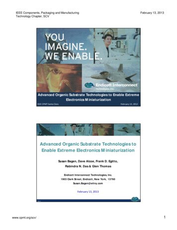
IEEE Components, Packaging and ManufacturingTechnology Chapter, SCVFebruary 13, 2013Advanced Organic Substrate Technologies to Enable ExtremeElectronics MiniaturizationIEEE CPMT Santa ClaraFebruary 13, 2012Page 1Advanced Organic Substrate Technologies toEnable Extreme Electronics MiniaturizationSusan Bagen, Dave Alcoe, Frank D. Egitto,Rabindra N. Das & Glen ThomasEndicott Interconnect Technologies, Inc.1903 Clark Street, Endicott, New York, 13760Susan.Bagen@eitny.comFebruary 13, 2013Page 2www.cpmt.org/scv/1
IEEE Components, Packaging and ManufacturingTechnology Chapter, SCVFebruary 13, 2013Agenda IntroductionThin Core Substrates vs. PWBsChip-Package InteractionOrganic vs. CeramicSystem-in-Package Building BlocksSystem-in-Package Case StudiesZ-Interconnect3D SolutionsExtreme Miniaturization with MicroflexNew Substrate Technologies: LCP & StretchablePage 3Benefits of Electronics MiniaturizationMarkets: Aerospace, Defense, Industrial & MedicalMACRO ELECTRONIC ASSEMBLIESIncreased Function & Integration(Servers, Medical Systems)MICRO ELECTRONIC ASSEMBLIESIncreased Function / Reduced SWaP(Implantables, biosensors,guidance sensors, UAVs, advancedreceptors)Page 4www.cpmt.org/scv/2
IEEE Components, Packaging and ManufacturingTechnology Chapter, SCVFebruary 13, 2013Rigid SubstratesThin Core Substrates vs. PWBsPage 5Rigid Substrates Electronics miniaturization drives the use of finepitch BGAs, CSPs and tiny SMT components, as wellas bare die.Substrate attributes have significant impact on the ability toreliably assemble these types of components and bare die. Dielectric material & filler: glass cloth vs. particle Substrate thickness Blind & buried vias Line width & space capabilityPage 6www.cpmt.org/scv/3
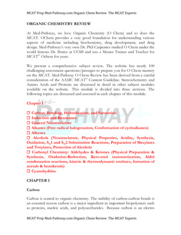
IEEE Components, Packaging and ManufacturingTechnology Chapter, SCVFebruary 13, 2013Thin Core Substrates vs. PWBsCross-section ComparisonCoreEZ 2-4-23 fully wireablebuild up layersStandard Build-up PWB 3-2-32 fully wireablebuild up layers2 fully wireablebuild up layersEpoxy-based with silicaparticle fill(Photos are to scale)3 build up layers onlyuseful for redistributionEpoxy-based with glass cloth- Thin core vias are 4x smaller- Thin core requires fewer costly build up layers for the same wiring capacity- Thinner core reduces electrical parasiticsPage 7Substrate expansion, combined with PTH restraint, creates Z-axisexpansion stress on BU & soldermask and potential halo delamination.Std BUZ-expansionStress on viaCoreEZThin core has much less deformation for BU & soldermask layers toabsorb, therefore, less stress and virtually no halo delamination.Page 8www.cpmt.org/scv/4
IEEE Components, Packaging and ManufacturingTechnology Chapter, SCVFebruary 13, 2013Limiting Attributes of PWBs for Bare Die Assembly Thick Core: Z-axis Expansion– Limits bare die assembly primarily to wirebond or onlysmall, low I/O flipchip die Glass Cloth Filler– Risk of CAF (conductive anodic filament) defects– Mechanical or CO2 drill– Surface topography can impact ability to achieveconductor fine lines and spacesPage 9Thin Core Substrates vs. PWBsVia Density Comparison Very Dense Package Interconnect– Ultra Dense Core Via Pitch caneliminate additional build up layers– When CVP is nearly die bump pitch,enables Z-escape to all wiring planes Dual Side Component Mounting Fine Line Width and Spacing– 18 – 25 µmUV Laser Drilled CoreEZ Thin Core:100 um diameter pad (50 um via)Standard Build-Up Mechanically drilled core:400 micron diameter pad, 200 um diameter viaHDI Substrate has 9X Core Via Density over conventional build up PWBPage 10www.cpmt.org/scv/5
IEEE Components, Packaging and ManufacturingTechnology Chapter, SCVFebruary 13, 2013Packaging Attributes ComparisonSubstrate features and advanced IC Assembly techniques enable bare die implementationAttributeStandard PWBCoreEZ SubstrateShrinkt itopportunityThrough viaMechanicalLaserThrough via dia.200 microns50 microns4XThrough via capture pad diameter400 microns100 microns4X3XLine Width75 microns18-25 micronsSpace Width75 microns18-25 microns3XSemiconductorsPackagedWirebondBare die or smallpackagepg4X to 10XEI’s 3-4-3 CoreEZ Flip Chip BumpPage 11Typical CoreEZ 10 Layer Cross-SectionCu-filled stacked microviasFlip Chip BumpsSoldermaskPSR400015 µm thickGND / TOPBuild-up layer 1Build-up layer 2Build-up layer 3Driclad, 35/50 µmthickS1PWR / GNDOuter coreDielectric, Driclad35/50 µm thickS2PWR / GNDInner core135 µm thickEpoxy/P-AramidPWR / GNDCore Cu12 µm thickS3PWR / GNDBuild-up Cu 1Build-up Cu 2Build-up Cu 312 µm thickS4GND / BOT 3-4-3 Stack up (10 copper layers)Substrate thickness 0.7 mmPage 12www.cpmt.org/scv/6
IEEE Components, Packaging and ManufacturingTechnology Chapter, SCVFebruary 13, 2013Typical HyperBGA 9 Layer Cross Section40 micron thick KPPEouter dielectricEr 3.23235 micron thick PTFEDielectric, Er 2.7ChippBumpNon soldermaskdefined padUnderfill15 thick Cu,redistributionmicrovia12 thick Cu50 micron thick PTFEDielectric, Er 2.715 thick Cu,redistribution6 Cu/38 Invar/6 CuGround plane12 thick Cu,50m dia. through viaKPPE filledBGA PadShown: 7 layer core with 1 build-up. Alternatives: Core (3-7 layer), BU to 3x layers.Can also use a traditional soldermask for SMD defined pads, if desired.Page 13Chip-Package InteractionPage 14www.cpmt.org/scv/7
IEEE Components, Packaging and ManufacturingTechnology Chapter, SCVFebruary 13, 2013Flip-Chip vs. WirebondWirebond:Active face is away from the substrate and associated die adhesiveDie adhesive material stress cracking avoids wirebond connections - at firstBegs questions: How far will crack run? Why did it happen? Thermal performance?Fracture / debond may notdamage the wirebondFlip-Chip:Die is 'flipped' so that electrical connections to substrate have very short lengthThe connections and active die face are in proximity to the substrate and underfillUnderfill is used to avoid stress to the electrical connectionsFailure of the underfill can quickly lead to electrical opensFracture / debond likely todamage the bumpThermal expansion of the Die vs Substrate is one fundamental driver of reliabilityPage 15Illustration of effect of CTE mismatch in view of temp changeAssume two very stiff layers of material, viewed in sectionLinear Expansion Only, with CTE α CTE βEquilibrium TemperatureαβCooledHeatedααββWith temperature change, dissimilar materials expand differently: “Mismatch”This expansion mismatch creates strain and stressThe strain and stress exists in either the materials, the bonding , or bothPage 16www.cpmt.org/scv/8
IEEE Components, Packaging and ManufacturingTechnology Chapter, SCVFebruary 13, 2013Illustration of effect of CTE mismatch in view of temp changeAssume two coupled flexible layers of material, viewed in sectionLinear Expansion, with CTE α CTE β creates bending stressPage 17Ball Grid Array Module attached to a PWBCTE mismatch effect, in view of temp reduction from solder reflowFlip-chip solder array attached to a substrate is analogousPage 18www.cpmt.org/scv/9
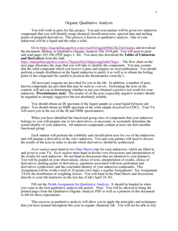
IEEE Components, Packaging and ManufacturingTechnology Chapter, SCVFebruary 13, 2013General OverviewPage 19Numerical Analysis for Die warp and Die stress Closed-form solution for unsymmetrical bending of linear elastic composite plate– 3-layer solution for die, underfill, substrateDie: 18mm square, E 21.8Mpsi, CTE 3ppm/C (constant throughout)Underfill: Typical high Tg, 100 micron thick (constant throughout)propertiespof interestSubstrate: Various p Stress: Uniform temp change from underfill cure to room temp Parametric analysis executed for two key variable clusters–Nominal die thickness 750 micronsNominal substrate modulus 3MpsiNominal substrate : modulus 3Mpsi, thickness 1000 microns, CTE 20 ppm/CN i l substrate:b t t modulusd l 3 Mpsi,M i thicknessthi k500 microns,iCTE 20 ppm/C/CNominalNominal substrate : modulus 3 Mpsi, thickness 500 microns, CTE 10 ppm/CResponse Measures:–– SubstrateDie thickness (10 microns to 10mm), several substrates of interest UnderfillSubstrate thickness range 10 microns to 10mm, with CTE range 5-30 ppm/C –DieMaximum die warpage (center to corner)Maximum principal stress on upper surface of die (away from substrate)MANY analysis were performed to create the following charts!Page 20www.cpmt.org/scv/10
IEEE Components, Packaging and ManufacturingTechnology Chapter, SCVFebruary 13, 2013Substrate Thickness & CTE EffectsComparison for common die size CTE difference fromsilicon is key driver Substrate thicknessgcreates a significantmaximum response valuefor both die stress anddie warpage For substrates above themaximal response value,thinning the substrate isworse For substrates below themaximal response value,thinningg the substrate isbetter Nominal substratemodulus 3 Mpsi To compare actualdesigns, their stiffnesswill vary, along withthickness & CTE30Die STRESS5 ppm/C30252015Die WARPHyperBGA105 ppm/CWafer-level pkgPWB rangeTypical flip-chip pkg rangePage 21Die Thickness EffectComparison for three nominal substrates Strong effect of siliconthickness on warpage Silicon must becomeextremely thin tounderpass maximum,maximum sothat most substrateapplication will warpMORE with thinner die Substrate propertieshave significant effect ondie warpage Starting from typical diethickness, stressgenerally drops as die isthinned, but eventuallyh pointi t wherehitreachesbecomes compressed20 ppm/C, 1000micron20 ppm/C, 500micronDie STRESS10 ppm/C, 500micron20 ppm/C, 500micron20 ppm/C, 1000micronDie WARP Thinned stacked die haspotential to create layerlayer debonding stress,depending on substratechoice (similar to ULKILD issues)10 ppm/C, 500micronStacked (unthinned)Typical thinnedTypicalASICPage 22www.cpmt.org/scv/11
IEEE Components, Packaging and ManufacturingTechnology Chapter, SCVFebruary 13, 2013Organic vs. Ceramic SubstratesPage 23Generalized Ceramic vs Organic Substrate Designand Performance DifferencesCeramic Stiffer Material can fracture High temperature resistance Minimal warpage Material shrinks substantially in fabCan be hard to control dimensions Higher dielectric constant material Thicker Substrate HeavierHeavier substrateCan affect assembly temperatures Expansion coefficient 5-10 ppm/CPkg size drives significant BGA stressColumns can be used to reduce Substrate is hermeticPackage could be hermetic with lid sealOrganic Compliant materials: More stretching Material can fatigue Material has temperature dependency Warpage controlsDesign balance, fixtures, lids Good dimensional control Better electrical performance Thin, light substrateDi sizei affectsff t BGA stresst DieGood for SOP applications Lower BGA stress No need for solder columns Non-hermeticMoisture effects on adhesionPage 24www.cpmt.org/scv/12
IEEE Components, Packaging and ManufacturingTechnology Chapter, SCVFebruary 13, 2013Weight Comparisons40 mm body size substrateApproximate substrateweight (gm)Ceramic (30 layer, alumina, 10mil/layer)48Ceramic (15 layer, alumina, 10 mil/layer)24PTFE BGA 9 layer substrate2.3Thi core buildb ild up 10 llayer substrateb t tThin292.9Thin core build up 6 layer substrate2.0Page 25HyperBGA Compliant Laminate Overview Deformation analogy–Consider solder column array deformations between ceramic & card–HyperBGA laminate internalizes deformations: Low stress Connections–SolderS ld connectionstiare low-profilelfil jointsj i t andd nott prone tot shearhdamagedCeramic Solder ColumnHyperBGAFree CTE valuesLid: 17Chip: 3Laminate: 11high standoffPC card: 18 Rigid, Brittle, Shrink-Fired Dielectric Elongated Solder Connections Shear Deformable Laminate Expansion Compensated Laminate Thin, Compliant Laminate Materials HyperBGA is designed for an optimal distribution of low stresses on BGA, internalcircuitry, underfill, chip, adhesives Very thin laminate contributes to reliable high density connectionsPage 26www.cpmt.org/scv/13
IEEE Components, Packaging and ManufacturingTechnology Chapter, SCVFebruary 13, 2013HyperBGA Compliant Laminate OverviewCeramic Solder Columndeformations in solderSCM HyperBGAdeformations internalizedhigh standofflow standoffMCM HyperBGAypdeformations internalized and localizedLidLaminatePWBPage 27Compliant Laminate Advantage Localized Deformation is ideal for multi-component reliability–Thin-film behavior of thin laminate: Very little interaction between components–Low stress interconnections exist for each subcomponent–Non-underfilled CSP and passives are successful–PWB Connections remain low-profile and not prone to shear damage The Lid combines roles of heatspreading and overall flatness control–Pre-attached laminate 'stiffener' is unnecessary, even with 0.5mm thick laminate–Use of thick aluminum lid provides extreme flatness and excellent PWB match–ALSIC material unnecessary so far–Compliant adhesives provide outstanding thermal and mechanical supportLidLaminatePWB MCM organic package size can be irrelevant to board level reliabilty through optimaldesign and construction.Page 28www.cpmt.org/scv/14
IEEE Components, Packaging and ManufacturingTechnology Chapter, SCVFebruary 13, 2013System-in-Package (SiP) Building BlocksPage 29Building BlocksSiP Fabrication & Assembly Technology Substrate Technology– Replace bulky, thick PWBs with thin, high density substratesCoreEZ 2-4-2242Standard BuildBuild-upup 33-2-323 Photos are same magnification. Vias are 4X smaller. Core via pitch matches die. Short via length for low Zexpansion stress.Page 30www.cpmt.org/scv/15
IEEE Components, Packaging and ManufacturingTechnology Chapter, SCVFebruary 13, 2013Building BlocksSiP Fabrication & Assembly Technology Embedding Resistors and Capacitors (R&C)– Remove discrete passive devices and incorporate into thesubstrate to reduce requiredqsurface areaCoreEZ 3-8-3with Embedded R&CPage 31Building BlocksSiP Fabrication & Assembly Technology – Bare Die Bare Semiconductor Die Unpackaged die hassignificantly smallerfootprint. Flipchip attach results insmallest configuration.DieSubstrateEmbedded DiePWBPage 32www.cpmt.org/scv/16
IEEE Components, Packaging and ManufacturingTechnology Chapter, SCVFebruary 13, 2013System-in-Package (SiP)Application ExamplesPage 33Size/Weight Reduction ExampleOriginal PCB 24 in2 , 383 components Core EZ Package Size- 31.75 mm diameter- 14 layer HDI Build up substrate 39 different part numbers, 231 components on 2surfaces 5 Bare Die– Flip Chip FPGA, 15.95mm x 10.23mm, 2,440 I/O– Flip Chip DSP, 4.68mm x 5.134mm, 225 um pitch,261I/O– Flip Chip Supply monitor, pitch 114 um, 16 I/O– Flip Chip DRAM, pitch 121 um, 86 i/o– Flip Chip Flash memory, pitch 116 um, 77 I/O SMT capacitors and resistors Buried resistors imbedded in substrate 1 SMT circular connectorCoreEZ 1.2 in2Page 34www.cpmt.org/scv/17
IEEE Components, Packaging and ManufacturingTechnology Chapter, SCVFebruary 13, 2013SiP Example for HiRel ApplicationOriginal PCBA reduced by 27X to the size of a single PBGA Component! Final Package Size: 55 x 55mm, 683um thick Substrate: Particle-filled epoxy ( CoreEZ) X-section 3-4-3 50um laser drilled microvias, 30/35um line/space 84 ft HDI wiring 39,000 40 micron UV laser drilled vias 5 Bare Flip Chip Die Discrete components: 0201 minimum size 638 SMT components placed Functional final socket & Bed of Nails topside test Custom Peripheral Pin connector & LidOriginal PWB 108 in2TopBottomCoreEZ High Density Interconnect SubstrateFlip Chip Die Bumps40 micron UV laser drilled microvias30/35um Line/spaceRedesigned SiP 4 in2Page 35Z-InterconnectPage 36www.cpmt.org/scv/18
IEEE Components, Packaging and ManufacturingTechnology Chapter, SCVFebruary 13, 2013Z-Interconnection Using 2S/1P Signal Coresand 0S/1P Joining CoresConnections Made Using Electrically Conductive PasteFabrication of core building tivePaste.followedfollowed by core laminationlamination.Page 37Controlled-Depth ViasBAA'ABAB'BConventional PTHs block wiringchannels. PTH stubs induce signalattenuation at high frequency.A'AB'BControlled-depth vias increasewiring density and eliminatestubs.Page 38www.cpmt.org/scv/19
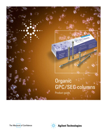
IEEE Components, Packaging and ManufacturingTechnology Chapter, SCVFebruary 13, 2013Why Z-Interconnect?Parallel vs. Sequential Process Yields100%Overall Yield80%60%40%2 Layer Sequential8 Layer Sequential2 Layer Parallel8 Layer Parallel20%0%100%90%80%70%60%Individual Layer YieldAssumes Layer Joining Yield 1 - 0.25 x (1 - Layer Yield)Page 39Nanotechnology : A Complete SolutionEndicott Interconnect Proprietary and ConfidentialPerformanceNano lexFull-ZBoard-ZJoining coreHyper-ZSinteringPage 40www.cpmt.org/scv/20
IEEE Components, Packaging and ManufacturingTechnology Chapter, SCVFebruary 13, 2013Z-Interconnect: Novel Means of Electrical Interconnect for theNext Generation of Electronic Packaging“Enables high performance printed wiring boards withhighest layer count at lowest cost.”HDI Z SubcompositesHDI Full Z Increases wiringg density.y Best signal integrity. Reduces signal attenuation athigh frequency. Shorter fabrication time. Higher Yield. Fewer wiring layers. High performance materials.EI patentedt t d dil ti EIdielectrics. EI patented electricallyconductive adhesives.Electrically Conductive AdhesivePage 41Z-Interconnect: Novel Means of ElectricalInterconnect for the Next Generation of ElectronicPackaging“Helps semiconductor packaging keep pace with the needs ofthe semiconductor marketplace.”ElectricallyConductiveAdhesive Increases wiring density. Best signal integrity. Reduces signal attenuation athigh frequency. Shorter fabrication time. Higher yield. Fewer wiring layers. Lower costcost. High performance materials. EI patented dielectrics. EI patented electricallyconductive adhesives.Page 42www.cpmt.org/scv/21
IEEE Components, Packaging and ManufacturingTechnology Chapter, SCVFebruary 13, 2013Z-Interconnect: Versatile Technology Low End PCB HD CardPWBComplexExpensive PCBPage 433D SolutionsPage 44www.cpmt.org/scv/22
IEEE Components, Packaging and ManufacturingTechnology Chapter, SCVFebruary 13, 20133D PackagingPackage-Interposer-Package (PIP) TechnologyA new 3D “Package Interposer Package” (PIP) solution is suitable forcombining multiple memory, ASICs, stacked die, stacked packaged die,etc., into a single package.Schematic of Package-Interposer-Package (PIP)construction with 4 packages and 3 interposersPage 453D PackagingPackage-Interposer-Package (PIP) TechnologyBenefits of Package-Interposer-Package High density, small pitch Re-workable and replaceable Polymer or ceramic interposer provides additionalsupport for improving stability and reliability PIP will experience less warpage and thermalstress Mitigates problems with coplanarity betweenpackages Interposer Options:– Dielectric material– Embedded passives– Embedded activesPage 46www.cpmt.org/scv/23
IEEE Components, Packaging and ManufacturingTechnology Chapter, SCVFebruary 13, 2013Package-Interposer-Package vs. POPPIP increases density while not adding to overall package thickness.Page 473D Multiple InterposersExample: 4 assembled packages connected with 3interposers.-Simpler assembled packages readily integratedinto resulting complex, high density 3D structure-Versatility of construction-Can be removed, repaired, upgradedPage 48www.cpmt.org/scv/24
IEEE Components, Packaging and ManufacturingTechnology Chapter, SCVFebruary 13, 20133D PackagingPackage-Interposer-Package (PIP) TechnologyPackage-Interposer Package (PiP)construction with multiple substratesA – Top ViewB- Cross-sectionDouble side assembled substrate withstacked packaged die (memoryattached to processor)Page 49Flexible SubstratesExtreme Electronics Miniaturization viaMicroflex AssembliesPage 50www.cpmt.org/scv/25
IEEE Components, Packaging and ManufacturingTechnology Chapter, SCVFebruary 13, 2013Microflex Device PackagingDie & Other Com
Substrate expansion, combined with PTH restraint, creates Z-axis expansion stress on BU & soldermask and potential halo delamination. Std BU Z-expansion Stress on via Page 8 CoreEZ Thin core has much less deformation for BU & soldermask layers to absorb, t