Transcription
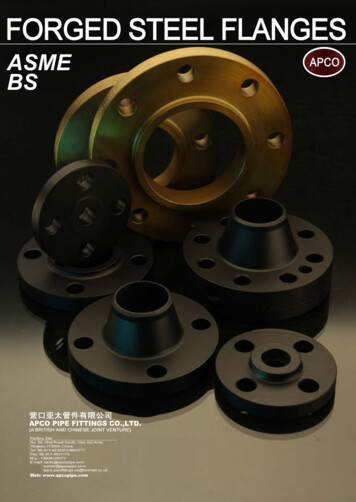
A R M Y LO R P T F E / P FALINED PIPESAND FITTINGSDIN 2848
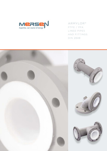
CONTENTMERSEN ANTICORROSION EQUIPMENTEXPERTISE p.1MERSEN ANTICORROSION EQUIPMENT p.2PTFE / PFA POLYMERS p.3The Mersen AntiCorrosion Equipment activity is internationally recognized for its expertise in the designand manufacture of process equipment, manufactured from corrosion resistant materials (graphite, siliconcarbide, tantalum, zirconium, PTFE).Mersen also has an in-depth knowledge of the process technologies requiring our AntiCorrosion Equipmentand can provide offers from the basic equipment only, up to skid-mounted turn-key process packages.PTFE / PFA LINING p.4STEEL PARTS p.7Since 1964, Mersen has been offering an exhaustive range of PTFE / PFA lined pipe and fittings especiallydesigned for conveying corrosive fluids in both the chemical and pharmaceutical industries.LINED COMPONENTS p.9THE PRODUCT RANGE CONSISTS OF :QUALITY CONTROL p.10INSTALLATION PROCEDURES p.11CODING SYSTEM AND REFERENCES p.13PTFE / PFA lined pipe and fittingsPTFE bellows (expansion joints) and compensatorsManifoldsDip pipesDouble jacketed pipingCustom made partsMANUFACTURING PROCESS p.14PRODUCTS p.15EXPERTISEMersen has an engineering team dedicatedto customer services.Our experts help study the best technical& economical solutions for your projects.This team can also assist our customers toproduce isometric drawings in order to create alist of fittings / components.The specification or data herein contained are only given for indication, withoutany undertakings whatsoever. Their publication does not suggest the matteris free of any rights whatsoever. Furthermore, due to constant evolution oftechniques and norms, we reserve the right to modify, at any time, thecharacteristics and specifications contained in this document.MERSEN refuses all and any responsibility concerning their use whateverthe purpose or application. Any copy, reproduction or information hereincontained, in whole or in part, made without MERSEN writtenconsent,is forbidden according to the laws of France and particularlythe lawnr. 92-597 of July 1st 1992 relating to the copyright.12
PTFE / PFA POLYMERSPTFE / PFA LININGDEFINITIONNOMINAL THICKNESSESAvailable lining materials for our product range are as follows :Mersen proposes 3 ranges of PTFE / PFA thicknesses :Virgin or anti-static* PTFE (Polytetrafluoroethylene), in accordancewith ASTM D4894 & 4895 standards.** Also on request according to DIN 53455 standardDNValues indicated in the following table are given for virgin PTFE and PFA.These characteristics can vary depending on the material grades from the various suppliers,the transformation process and the batch.UNITSPTFEPFAPhysicalTensile strengthElongation at breakModulus of elasticity under elongationModulus of elasticity under flexural 4.03.54.07.03.53.54.54.54.04.09.02.13 - 2.192.12 - 2.1765% 5.04.88.05.09.05.05.06.010.0MPa20 - 4027 - 321504.05.35.09.56.010.05.05.36.06.011.0%250 - 500300 - 5002004.06.27.010.06.012.06.06.28.07.012.0MPa350 - 750650 - .54.5MPaHardness shore D mandhod440 - 670590 - 70050 - 7260 - 65ThermalFlame propagationhardhardMelting point C327 and 342300 to 310Other transitions C-90*, 123,* 27**-80*, 90*Maximum service temperature C-200/ 260-150/ 260Temp. of deflection under load (1.82 MPa) C50 - 6050Linear elongation coefficient105 / C10 - 2512Thermal conductivityW / m.K0.240.252.22.1ElectricalDielectric constant from 60 Hz to 107 HzVolume resistivityΩ.cm10181018Surface resistivityΩ10171017kV / mm.K36(1)80(2.3)*amorphous phase, **crystal phaseRECEIVING INSPECTIONSMaterial certificates from the PTFE / PFA powder manufacturers are checked and identified with batchnumbers. On request, FDA certificates (Food and Drug Administration) can be supplied.3GINSTRUMENTTEES3.0g/cm3MechanicalVCONC . / EXC.RED .TEESThe minimal thickness of the PTFE tube is equal to the nominal minus 10% - The thickness of the flare cannot be lower than the nominal thickness, minus 20%.TESTS ON PTFE / PFAPhysical and mechanical testsFor each manufacturing batch, Mersen checks the mechanical & physical properties.Values for elongation at break point and tensile strength, together with regularity of the graph confirmsthat the liner sintering has re-established the isotropy of PTFE, which guarantees a low level or permeability.Parallel directionPerpendicular directionStress in MPaWater absorption : 24h thickness 3,2 mmELBOWSStress in MPaDensitySpark test (thick.mm)SPOOLSGGENERAL CHARACTERISTICSPROPERTIESThiknesses G and Vare indicated in the table belowPTFE / PFA NOMINAL THICKNESSVirgin or anti-static* PFA (perfluoroalkoxy), according to ASTM D3307** standard.* Conductive black PTFE or PFA}ARMYLOR G to operate under pressureARMYLOR V to operate under pressure and vaccumARMYLOR S for severe applications Ask usStrain in %Strain in %4
PTFE / PFA LININGOptimal density ensures a balance between a low permeability level and a good distortion duringtemperature cycles.MECHANICAL PROPERTIESPHYSICAL PROPERTIESTensile strengthElongation at breakDensityPTFE ExtrudedVirginTest accordingto standard 21 N/mm2² (// Direction) 17 N/mm2 ( Direction)ASTM D4895 250% (// Direction) 200% ( SDirection)ASTM D48952.14 - 2.19ASTM D7922.13 - 2.19DIN 53749AntistaticTest accordingto standard 21 N/mm2 (// Direction) 17 N/mm2² ( Direction)ASTM D4895 250% (// Direction) 200% ( Direction)ASTM D48952.13 - 2.19ASTM D7922.12 - 2.18DIN 53749Thanks to Mersen’s expertise in lining technologies (PFA injection, extrusion of fine PTFE powders, Isomoulding).Mersen has optimised its manufacturing processes and PTFE / PFA thicknesses in order to limit thepermeability rate.OPTIMIZING THE LINER THICKNESS - PERMEABILITYSEVERAL FACTORS HAVE AN INFLUENCE :Thickness of the liner is the most significant factor. The chart below shows the sharp decreaseof permeability versus thickness.Size of the ions or molecules : the Helium permeability curve shows the ability of a very smallmolecule such as helium to pass through the PTFE / PFA.Chemical nature of the product : any chemical similarity between the material passing through andthe material passed through increases permeability. 21 N/mm2ASTM D4894 250%ASTM D4894 2.14 - 2.19ASTM D7922.13 - 2.19DIN 53749AntistaticTest accordingto standard 21 N/mm2ASTM D4894 250%ASTM D48942.14 - 2.19ASTM D7922.12 - 2.18DIN 53749PFAVirginTest accordingto standard 26 N/mm2ASTM D3307 300%ASTM D33072.12 - 2.17ASTM D7922.12 - 2.17DIN 53749AntistaticTest accordingto standard 26 N/mm2ASTM D3307 300%ASTM D33072.11 - 2.17ASTM D7922.11 - 2.16DIN 53749Temperature and pressure: permeability increases with temperature and pressure.EXAMPLES OF PERMEABILITY CURVES :PTFE / PFA permeability curveChlorine (mg/m2.h)PTFE MoldingVirginTest accordingto standardThe results comply with the ASTM F1545 standardLiner thickness (mm)Helium permeability PTFE / PFA curveHelium rate (mbar.l/s)ANTISTATIC PTFE / PFA ELECTRICAL PROPERTIESTransverse resistivity : 107 Ω based on the BS ISO 2878 : 2005 standardSurface resistivity : 108 Ω based on the BS ISO 14309 : 2011 standardVolume resistivity : 108 Ω based on the BS ISO 14309 : 2011 standardTime (min.)56
STEEL PARTSCOMPONENTSWELDINGThe table below shows the various steel components used for manufacturing our standard pieces.3.1 mill certificates in accordance with EN 10204 are available on request.ASTM or JIS standards compliant steel grades, low temperature or stainless steel grades can be supplied onrequest. Please contact us for more information.Mersen is qualified in accordance with the European standards EN ISO 15614-1 (for WPQR’s) and EN ISO9606-1 (for WPQ’s), with German ADM HP 5.3 and with ASME Section IX for GMAW, FCAW, GTAW andSAW processes. These qualifications are renewed on a regular basis, either by Mersen IWE (InternationalWelding Engineer) or by Third Parties (German TÜV or French Apave). Suppliers’ assessments areperformed by Mersen in order to make sure that the same quality standards are implemented.FLARED STUB ENDSPIPES / BODIESFLANGESSpools are built with 2 loose flanges on collars obtained by cold forming of the steel tube, from DN 15 to DN300. This process has been assessed by Notified Bodies and found compliant with the essential requirementsof the PED. A loose flange stop can be supplied on ONALSTANDARDMIN. GRADEVENT HOLESTHE STEEL PARTS OF THE PTFE / PFA LINED FITTINGS ARE DRILLED WITH VENT HOLES IN ORDER TO :SPOOLSEN 10216P 235 GH / EN 10216EN 1092P 245 GH / EN 10222Prevent any back pressure between the metallic housing and the liner.Detect any leakage during pressure tests.ELBOWSEN 10253CAST STEELELBOWS AND TEESP 235 GH / EN 10216EN 1092P 245 GH / EN 10222Quickly detect any sign of corrosion.Spools with length below 500 mm have one 3 mm diameter vent hole in the middle of the piece. Those above 500 mm are fitted with two vent holes locatedabout 150 mm from each end. The fittings have at least one 3 mm diamander vent hole. Reducing flanges, blind flanges and spacers do not have any ventholes. In the case of particular specifications or thermal insulation piping, vent bosses can be welded to the vent holes.GP 240GHVENT BOSSESTEES AND CROSSESEN 10216P 235 GH / EN 10216EN 1092P 245 GH / EN 10222CONCENTRICREDUCERSEN 10253P 235 GH / EN 10216EN 1092P 245 GH / EN 10222REDUCING FLANGESEN 1092SPACERSP 245 GH / EN 10028P 245 GH / EN 10028If vent holes must be identified quickly or when the piping isthermal insulated, a coupling can be welded on tothe vent holes. In the case of different thermal insulationthicknesses, an extension stem can be screwed on to the coupling.ELECTRICAL CONTINUITYThe electrical continuity of lined piping can be ensured byconnecting each individual component together by usingconductors linked to earthing lugs.The latter are welded in the middle of the steel part for fittingsand spools below 500 mm long and at about 150 mm from theback side of each flange for spools above 500 mm long.Types A or B earthing lugs can be proposed on request.Standard materials are 304 or 316 stainless steel grades.Other materials can be supplied on request.INSTRUMENT TEESEN 10216P 235 GH / EN 10216/ EN 10028EN 1092P 245 GH / EN 10222PAINTINGThe standard coating is a 40 μm thick zinc epoxy primer coating on sand blasted steel, inaccordance with the S.A 2.5 cleanliness level. Other surface preparations, undercoats or topcoats canbe applied on request.78
LINED COMPONENTSQUALITY CONTROLDIMENSIONAL TOLERANCESINSPECTIONS AND TESTS PROGRAMThe lined pieces and their dimensions are indicated in pages 17 to 35.All the lined pieces are built using the following tolerances :MERSEN manufactures PTFE-lined piping and fittings compliant with the the European Pressure EquipmentDirective 2014/68/UE (previously 97/23/CE). Type agreements are awarded by the APAVE Notified Body(CE 0060) for the whole range of ARMYLOR products. In addition to assessments carried out by ThirdParties and continuous internal audits, a complete inspection and tests program is set during the entiremanufacturing process :DIMENSIONALTOLERANCEANGULARTOLERANCE0 - 315 mm 0; -3 mm 0.5 315 - 1000 mm 0; -4 mm 0.5 1000 - 6000 mm 0; -5 mm 0.5 DN 25 - 100 0; -3 mm 0.5 DN 125 - 200 0; -4 mm 0.5 DN 250 - 600 0; -5 mm 0.5 DIMENSIONLENGTHSDIAMETERSRaw material (fluoropolymers) : acceptance criteria at receiving inspections, physical properties ofthe liners monitored throughout the manufacturing process.Spark tests are performed on each PTFE and PFA-lined piece in the following conditions :voltage of 5000* E (E thickness of liner in mm) with a maximum of 25000 V.Dimensional and visual examination of the liners and steel parts :the weld aspect, the overall dimensions, the size of the collars, the liner thickness, the absence ofsurface defects and the painting thickness are checked.Tolerance for PTFE / PFA : 5%TEMPERATURE CYCLE TESTSThe pieces tested undergo 100 alternate steam / cold water cycles, according to the ASTM F1545 standard.Steam is absorbed by the liner under the influence of both temperature and pressure.Vacuum resistance of the liner is then proved due to significant mechanical stresses causedby the sudden pressure drop combined with fast cooling.VACUUM RESISTANCEDN152025324050ARMYLOR GVacuum 2 Torr 150 CARMYLOR VVacuum 2 Torr 230 C6580100125200250300350400 Vacuum 2 Torr150 C2 Torr100 CVacuum according to particularspecificationsARMYLOR SUnits : 760 Torrs 760 mmHg 1 bar 1 kg/cm2² 105 Pa 14.7 PsiNon-destructive examinations are carried out when required by the applicable standardsor on request. RT and PT are performed by COFREND level II qualified personnel.Pressure tests : depending on the lining process, a hydrostatic or a pneumatic test is performed.A hydrostatic test is performed on pieces fitted with vent holes, injected or produced from tubes.A pneumatic test is carried out on isomolded pieces and on some pieces produced from extruded liners.TRACEABILITY AND MARKINGIN ADDITION TO THE INSPECTIONS AND TESTS PROGRAM, A FULL TRACEABILITY SYSTEM OFMATERIALS IS IMPLEMENTED :Steel parts : a coded marking system with unique traceability to the mill certificates is used. Eachpiece is cold stamped. Marking transfers by Mersen qualified personnel are approved by Mersen’sNotified Body.Finished product : the following information is stamped on the finished piece :The initials of Mersen, the order number and the piece number (Manufacturing number)The «CE» symbol followed by the Notified Body registration number when applicable.Traceability of documents : total traceability is ensured with the same method for both steel andlining materials.Coded marking pertaining to mill certificateOrder number Manufacturing numberCE symbol Notified Bodynumber (when applicable)9Additionnal marking can be done.On request, each part can be identified thanks to a heattransfer printed sticky label that shows piece referenceand isometric number.10
INSTALLATION PROCEDUREInstallation and maintenance instructions are provided in the user’s manual delivered with the products.Specific items are highlighted here after.BOLT LENGTHSThe table below specifies the recommended lengths of threaded stems for the various assemblies.PRECAUTIONSFIXED F. / FIXED F.LOOSE F. / LOOSE F.FIXED F. / LOOSE F.FLARE STUB ENDThe lined steel components are delivered with wooden or plastic blanks installed to protect the PTFE / PFAflange faces. Remove these protective blanks when the components are about to be connected only : theyshall be refitted after each inspection and when the piece is withdrawn from the installation. Once theblanks have been removed, the greatest care is required : no contact with the ground, absence of any sharpobject that could damage the liner. Never weld on lined parts.CLEANINGFlared surface must be carefully cleaned prior to connection.BOLT TIGHTENINGTHE DIMENSIONS INDICATED REFER TO :The assembly of PTFE / PFA lined components does not require any gaskets except when materials ofdifferent natures are being coupled or during successive assembling and dismantling operations.TIGHTENING BOLTS :A tightening torque equal equal to 1/3 the diameter of the threaded stems.A nut height equal to the diameter of the threaded stems.Insert the washers.Clean and grease the bolts.Tighten nuts by hands.Tighten each bolt using a torque wrench,keeping to the torque values specifiedin the table beside.Cross-tightening as with any flange connection.Tightening torque values are given for PTFE / PFA andmay vary depending on greasing and the condition ofthe nuts and bolts.Values are given for PN 10 flanges. They are indicatedfor room temperature and must always be checkedin cold conditions, after 24 hours of operation, thenchecked periodically.THE TIGHTENING TORQUE VALUESINDICATED BESIDE APPLY TO :Class 8.8 steel nuts(resistant to 800 N/mm2 rupture,elasticity limit of 640 N/mm2).0.12. nut friction coefficient.11DNBOLTSmmTORQUEN.mDN 254 x M1230DN 324 x M1645DN 404 x M1660DN 504 x M1680DN 654 x M16100DN 808 x M1660DN 1008 x M1670DN 1258 x M1690DN 1508 x M20130DN 2008 x M20180DN 25012 x M20160DN 30012 x M20210DN 35016 x M20260DN 40016 x M24330DN 45020 x M24290DN 50020 x M24330DN 60020 x M27460VENT HOLESVent holes must not be obstructed by thermalinsulation or painting. Where thermal insulationis fitted, vent extensions should be provided.When pipes are operated for the first time,air or water trapped inside at the momentof assembly may escape through the vent holes.It is recommended, during periodic inspection,to check that no trace of leakage is visiblearound the vent holes. The latter also act ascorrosion indicators.WEIGHTThe weight (kg) of each piece is indicatedon the corresponding tables. Due to the variousconstruction methods, the weights are typical valuesonly. The tolerance is /- 10%.SUPPORTSElements must be supported using collars that are notwelded on the lined piping. Never weld on lined parts.However, supporting elements may be welded prior tolining.12DNL1mmL2mmL3mmL4mmDN 15759585DN 208010090DN 25801059085DN 329011510595DN 409011510595DN 509512010595DN 6595125110100DN 80100130115105DN 100105130115115DN 125110135120DN 150120150135120DN 200125155140140DN 250130165145145DN 300130175150150DN 350135180155155DN 400160205175DN 450170205175DN 500170230190DN 600170235190
MANUFACTURING PROCESSEach element has its own unique reference which allows its identification.This reference is composed on 16 alphanumeric characters. In some cases, the character can be «-» if refersto standard. The references that are mentioned in the dimensional tables are the standard ones.RANGEPIECES TYPENB LOOSEFLANGESSTEEL SHELLPARTICULARITYD DIN- STANDARD GL PIPE LENGTH IN MM1, 2, 3, 4- STANDARD- STANDARDA ANSIV PRESSURE& VACCUMC ELBOW ANGLEK CAST STEELA SUPPORT LEGS SPECIALS SPECIALR LOWTEMPERATURESTEELB COUPLINGX STAINLESSSTEELC SUPPORT LEG COUPLINGEXTRUSIONDIMENSIONPOWDERPASTE 16LININGDN1 PN10- VIRGINSTANDARDSEE TABLEUNDERCONSTRUCTIONLINING PROCESS- STANDARD- PASTEEXTRUSIONC TUB ENDCOLLARM ISO-MOLDING3 PN 16P SLIP ONFLANGET TRANSFERMOLDING4 PN 50W FLARE2 PN 20/150LBS5 PN 40A NGFLARINGCONNECTIONWELDINGGRINDINGPULLINGS SPECIALC1MACHININGSTEEL WORKSHOPCODING SYSTEM AND REFERENCESTESTAccordingto eachproductPAINTINGSHIPMENTExamples :D3V-L1234T--XW-A :DIN, PN16, vaccum range, 1234 mmstraight length, DN200, inox steel,welding neck, earthing lug.D1--C45--P-1 :DIN, PN10, 45 elbow,DN80, 1 loose flange.14
PRODUCTS DATA SHEETSDIN FLANGES PN 10 AND PIPESDIN FLANGES PN 10 AND PIPES p.16DIMENSIONAL TOLERANCESFLANGED SPOOLS p.17The whole range of flanged products from DN15 to DN600 can be equippedwith loose or fixed flanges on request.ELBOWS p.18DIAMETERSEQUAL TEES p.19DNDdx* dyTHICKNESSkb1b2b3DRILLING PN10b4holesmm mm mm mm mm mm mm mm nb xREDUCING TEES p.20-21boltingøSTEEL M1233.72.6INSTRUMENT TEES p.26321407867100161616124x18M1642.42.6CROSSES 1676.12.9SPECTACLE BLINDS p.3080200 138130 160201820168x18M1688.93.2BLIND FLANGES & LATERAL TEES p.31100220 158158180201820168x18M16114.33.6125250 188188210221822188x18M16139.74.0150285 212212 240221822188x22M20168.34.5200340 268 268 295242024208x22M20219.16.3250395 320 320 3502622262212x22M20273
PTFE bellows (expansion joints) and compensators Manifolds Dip pipes Double jacketed piping Custom made parts Mersen has an engineering team dedicated to customer services. Our experts help study the best technical & economical solutions for your projects. This team can also assist our cus
