Transcription
Cover sheetHow do you configure a Virtual LocalArea Network (VLAN) in PCS 7?SIMATIC PCS 7FAQ January 2013Service & SupportAnswers for industry.
QuestionThis entry originates from the Siemens Industry Online Support. The conditions ofuse specified there apply (www.siemens.com/terms of use).Go to the following link to download this view/en/66807297CautionThe functions and solutions described in this article confine themselvespredominantly to the realization of the automation task. Furthermore, please takeinto account that corresponding protective measures have to be taken in thecontext of Industrial Security when connecting your equipment to other parts of theplant, the enterprise network or the internet. Further information can be found inEntry ID: view/en/50203404QuestionHow do you configure a Virtual Local Area Network (VLAN) in PCS 7?AnswerFollow the descriptions, instructions and notes listed in this document for a detailedanswer to the above question.2How do you configure a VLAN in PCS 7?V 1.0, Entry ID: 66807297
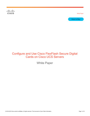
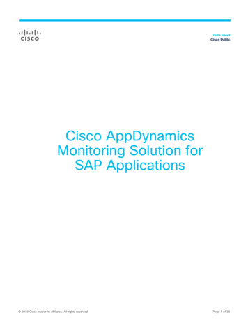
Using VLANs in PCS 7Below we give you an overview of the use and structure of VLAN technology in thePCS 7 environment. There is also a description of the configuration of the devicesin the network.NoteThere are restrictions on the use of VLANs in PCS 7.The implementation of a redundant connection via VLAN is not recommended,inter alia, for reasons of availability. This could lead to unexpected orunrequested behavior of the system.What is a VLAN?A Virtual Local Area Network (VLAN) is a logical subnetwork. This subnetwork canbe assigned to a switch or be an entire physical network.Figure 1How do you configure a VLAN in PCS 7?V 1.0, Entry ID: 668072973
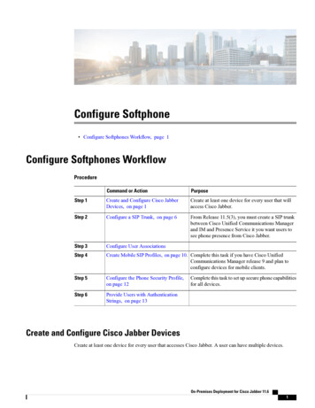
The subnetwork can extend beyond one or multiple switches. A VLAN dividesphysical networks into logical subnetworks. VLAN-compatible switches split up theframes (data packages) between the separate VLANs. The frames are notforwarded to another VLAN even though the subnetworks might be connected tocommon switches.Figure 2More information is available in the FAQ entry n/317703964How do you configure a VLAN in PCS 7?V 1.0, Entry ID: 66807297
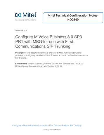
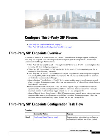
When do you use VLANs in PCS 7?The use of VLANs in the PCS 7 environment is limited to the applications below.·Combined plant and terminal busThis architecture consists of just one physical Ethernet network that is used forboth the plant bus and the terminal bus. VLAN separates these two networklevels on a logical level. By using a common medium, the networks mightinfluence one another. The separation of communication networksrecommended for PCS 7 is achieved on a logical level.·VMware ESXi server in virtual infrastructuresIn virtual infrastructures various PC stations (OS clients, for example) arevirtualized together on one server. This means that not all the PC stations haveto be physically present.Figure 3More information is available in the FAQ entry n/31770396How do you configure a VLAN in PCS 7?V 1.0, Entry ID: 668072975
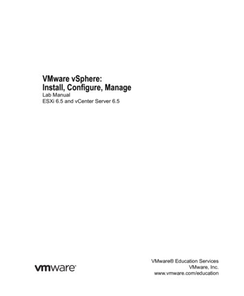
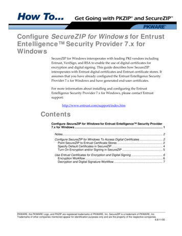
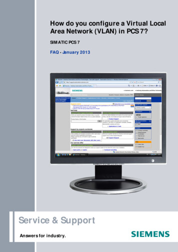
Which devices are needed for using VLANs?VLAN-compatible switches are needed for using VLANs in the PCS 7 environment.The following switches from the Siemens network device family support port-basedVLANs with tagged frames:·SCALANCE X-300·SCALANCE X-400·SCALANCE X-500When you configure the switch you define which VLAN is assigned to which port ofthe switch and therefore also the nodes connected to it.The port-specific VLAN tags serve as identification.·A VLAN tag is added to a message (Ingress) when received on the switch froma terminal node.·A VLAN tag is removed from a message (Egress) when sent from the switch toa terminal node.In the case of communication between two switches (Trunk) the VLAN tags are notremoved when leaving the switch. When received, the VLAN tags are retained inthe partner switch which ensures that the VLANs remain separated.Tagged messages are always used in the switch.Figure 4More information is available in the FAQ entry n/196251086How do you configure a VLAN in PCS 7?V 1.0, Entry ID: 66807297
How do you configure VLANs for use in PCS 7?The following configuration instructions show how to create two static VLANs for aterminal bus and a plant bus.Refer to the following manual for more configuration parameters:"SIMATIC NET Industrial Ethernet Switches SCALANCE X-300 SCALANCE X-400Configuration ew/en/19625108Proceed as follows for the configuration:1. Define the criteria for creating at least two or more VLANs.2. Assign the nodes to the separate VLANs.3. Create a configuration list.4. Assign the VLAN ID for each node and each switch.5. Define to which device and at which port there is a connection.Configure the switch as follows:1. Define all the VLANs used on this device.2. Define which VLAN is to be supported on which port.3. Define how the messages are to be processed at the input and output sides ofthe port (ingress and egress filters).4. Specify whether messages at the port are to be sent with or without tag.How do you configure a VLAN in PCS 7?V 1.0, Entry ID: 668072977
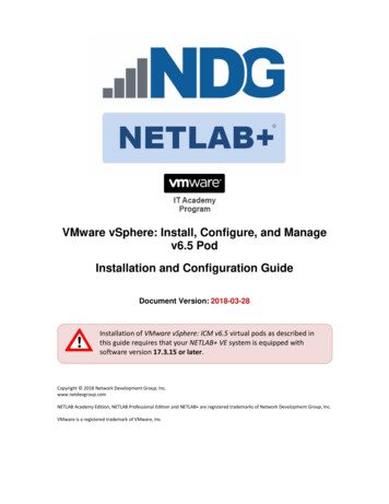
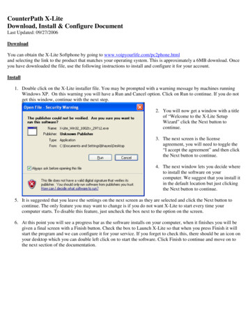
Before configuring the VLANs you should make sure that the Web-basedManagement of the switch can be reached from each port during and afterparameterization of the VLAN.Figure 5Open the "Web-based Management" and in the "Agent" menu you enable the"Accessible in all VLANs" function.For switches that do not have this option make sure that at least one port of theswitch is in the "Agent VLAN" or that the "Agent VLAN" is changed according to theport configuration.WARNING8If the parameters are set incorrectly, it is possible that the web interfaceand the configuration of the switch can no longer be called.How do you configure a VLAN in PCS 7?V 1.0, Entry ID: 66807297
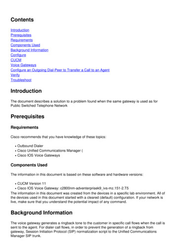
ConfigurationFigure 6The "Current VLAN Configuration" page shows the current VLAN configurationparameters of the port.Table 1AbbreviationsDescription–The port is not a member of the specified VLAN.MMember: The port is member of the VLAN; sent messages receive aVLAN tag with the VID specified in the first column.RRegistered: The port is member of the VLAN; registration was through aGVRP message.UUntagged: The port is member of the VLAN; sent messages do notreceive a VLAN tag.FForbidden: The port is not member of the VLAN and it is not possible fora VLAN to be registered dynamically at this port by means of GVRP.In the case of a new definition all the ports are preset with the ID "–".A switch that supports VLAN is parameterized by default on all ports with the VLANID "1" (default VLAN).The VLAN-ID "500" is reserved and already configured for a future application.All the ports on the switch send messages by default without a VLAN tag to ensurethat the terminal nodes can receive the messages.This basic setting is necessary because it is not sure whether a node can interprettagged frames.How do you configure a VLAN in PCS 7?V 1.0, Entry ID: 668072979
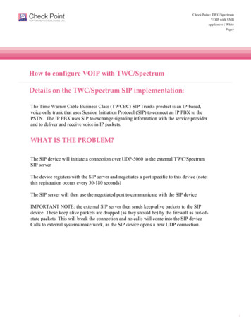
Figure 7Click the "New Entry" button or click an available configuration to assign ports to aVLAN. The "Static VLAN Configuration" page is displayed.Create a new VLAN for the terminal bus. Define a unique VLAN ID of your choice(from area 2 – 4096. In the example: VLAN ID 10). Now select the ports to beused for the terminal bus.Set "U" for the ports to which terminal nodes are connected (Static Access Port).Set "M" for ring ports or connection ports that lead to other switches (Trunk Port).NoteIf a VLAN is to communicate through the ring ports, the ring ports must belocated in the VLAN. In the case of multiple VLANs the ring ports must beconfigured accordingly in each of the VLANs concerned.Now create a new VLAN for the plant bus. Proceed exactly as for the configurationof terminal bus VLAN.In our example we have selected the VLAN ID "20" for the plant bus.10How do you configure a VLAN in PCS 7?V 1.0, Entry ID: 66807297
Figure 8On the "Current VLAN Configuration" page you select the item "Default VLAN 1".Set "–" for all the ports to be used for the terminal bus and the plant bus.Set "U" for all the ports not used.Set "M" for ring ports or connection ports that lead to other switches (Trunk Port).How do you configure a VLAN in PCS 7?V 1.0, Entry ID: 6680729711
Figure 9The "Current VLAN Configuration" page shows the current VLAN configurationparameters of the ports for the terminal bus and the plant bus.The overview shows which VLANs are created and at which ports messages of thecorresponding VLANs are output (Egress Configuration).12How do you configure a VLAN in PCS 7?V 1.0, Entry ID: 66807297
In the next step we define the input behavior (Ingress behavior) of the switch forthe VLANs concerned.Figure 10On the "VLAN Port Configuration" page all the ports have their associated Port IDs:·The ports on the terminal bus have the Port VLAN ID of the terminal bus.·The ports on the plant bus have the Port VLAN ID of the plant bus.How do you configure a VLAN in PCS 7?V 1.0, Entry ID: 6680729713
Figure 11On the "VLAN Port Parameters" page all the ports are displayed with theirconfigured Port VLAN IDs and the associated Ingress behavior.Untagged messages sent to the switch receive the relevant VLAN tag dependingon the configured Ingress behavior.The basic parameterization of the VLANs for the terminal bus and plant bus iscompleted.The networks are defined port specific and are separated logically. Directcommunication between nodes of the plant bus and nodes of the terminal bus isnot possible.14How do you configure a VLAN in PCS 7?V 1.0, Entry ID: 66807297
both the plant bus and the terminal bus. VLAN separates these two network levels on a logical level. By using a common medium, the networks might influence one another. The separation of communication networks recommended for PCS 7 is achieved on a logical