Transcription
Fan Clutches20.02General InformationGeneral InformationThe fan clutch engages and disengages the fanclutch hub with the engine fan. When they are engaged, the fan turns, to pull cooling air through theradiator, the charge air cooler, and the air conditioning condenser. When the fan clutch is disengaged,the engine does not turn the fan. This maintainsproper cooling, and enables the air conditioning towork.A large engine-cooling fan may require 70 to 100 engine horsepower to spin it. That reduces power available to move the vehicle, adds to engine noise, anduses more fuel. The fan clutch disengages when thefan is not needed, so the vehicle can operate as efficiently and quietly as possible.Most Freightliner fan clutches are actuated by compressed air. A solenoid-controlled valve regulates thesupply of compressed air to the fan clutch to engageand disengage the fan. Freightliner fan clutches normally disengage the fan when air is routed to them,and engage the fan when the air supply is blocked.switch’s set point. The switch then signals thesolenoid valve to engage the fan drive. The fanpulls cooling air through the air conditionercondenser coils, to cool the condenser/refrigerant and reduce refrigerant pressure. An optional manual override switch, located onthe vehicle dashboard.The solenoid valve is the heart of the control system,opening and closing to regulate the air flow to the fandrive. It is a 3-way valve, having two inlet/exhaustports and one outlet port. Air pressure from the vehicle’s air system feeds into one of the inlet ports (depending whether the system is normally open or normally closed) and the outlet port is connected to thefan drive. The plunger connects the solenoid outletport to the normally-open port, on Freightliner vehicles. Turning the electric current to the solenoidvalve on and off causes a plunger inside the solenoidvalve to move up and down.In the normally-open control system, when allswitches are below their set points, they are openand no electrical current reaches the solenoid valve.For the specific conditions that should trigger the engine fan, refer to your engine manufacturer’s specifications.The solenoid valve has a 3/64-inch (1.2 mm) orificeto regulate the volume of air and ensure smooth engagement and disengagement of the fan drive.In older vehicles, the fan clutch is controlled by anelectrical circuit containing three switches. Theswitches are wired in parallel so that any one ofthem can trigger the closing of the solenoid valve, tocut air pressure to the fan clutch and cause the cooling fan to spin. See Fig. 1The normally-open valve outlet port is always connected to the fan drive.The three switches are: A temperature switch, sensing the engine coolant temperature. In a normally-open temperature switch, the electrical contacts are openwhen the temperature is below the set point,and closed when the temperature is above theset point. A refrigerant pressure switch is installed in thevehicle’s air conditioning system. When the airconditioner is running, the refrigerant absorbsheat from the air in the cab, through theevaporator. The heated refrigerant goesthrough tubing to the air conditioning condenser, which is in front of the engine radiator.As the refrigerant heats, the pressure rises inthe air conditioner high pressure line, until therefrigerant pressure reaches the pressureCentury Class Trucks Workshop Manual, Supplement 6, September 2004Mounting the solenoid valve in a location away fromthe engine minimizes the valve’s exposure to excessive heat, vibration and contaminants, and prolongsthe life of the solenoid valve.Newer vehicles monitor and control all engine functions, including the fan drive, with the Electronic Control Module (ECM). An ECM consists of a digital microprocessor, random access memory (RAM), andread only memory (ROM). The ROM contains thecomputer’s program. Programmers can change avehicle’s control systems and performance, simply bychanging the ROM’s programming.NOTE: Minimum fan-on time for air conditionerengagements should be no shorter than 120seconds, and the fan clutch should be set toengage 10 F (12 C) above the temperature atwhich the thermostat is fully open. Reducing thenumber of times the fan clutch engages anddisengages extends the life of the fan clutch.050/1
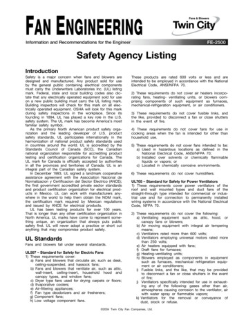
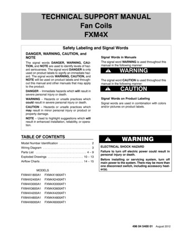
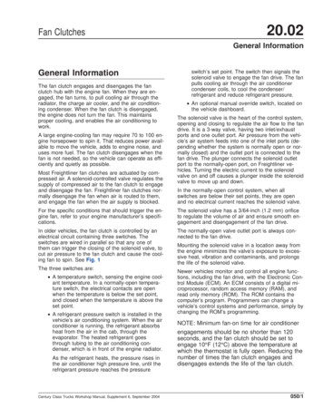
20.02Fan ClutchesGeneral anual Override SwitchCoolant Temperature SwitchA/C Refrigerant Pressure SwitchAir FilterAir Supply to Solenoid ValveSolenoid ValveFan ClutchFig. 1ECM-equipped vehicles have no direct connectionbetween the sensors and the solenoid valve. Instead,information from sensors and switches feeds into theECM, and the ECM then controls the solenoid valve.The solenoid valve controls the compressed air supply, to engage or disengage the fan clutch. SeeFig. 1.050/2ECM systems are more reliable and simpler than independent hard-wired systems. The computer program sets the conditions when the fan will be engaged, and all sensors and actuators are wired tothe ECM, instead of to each other. This providesmore efficient and appropriate component operation.Century Class Trucks Workshop Manual, Supplement 6, September 2004
Fan Clutches20.02General InformationIn an ECM-controlled system, a given sensor mayaffect several actuators and an actuator may be affected by several sensors, depending on how theECM is programmed.The ECM computer monitors the data from the sensors. Then, it sends the appropriate signals to thecontrols and actuators based on programming logic.The ECM also sends status information to the operator’s warning lights and gauges.Sensors used in ECM systems are different fromthose used in non-ECM systems. In ECM systems,sensors only send digital measurements. In nonECM systems, the sensors control switches, to openor close individual circuits.Instead of the simple open/close type of sensor,ECM systems use thermistors and sending units tosend signals to the ECM (temperature, pressure,speed, or whatever function is being sensed). Forexample, instead of a thermal switch opening or closing at a preset temperature, ECMs use a temperature sensor to set exact voltage, which the logic program converts into an precise temperaturemeasurement. Instead of simply knowing if the coolant temperature is above or below the set point, forexample, hotter than 190 F (88 C), the programknows the exact temperature; for example, 196.4 F(91.3 C). This makes control of the cooling systemmore precise and efficient.In an ECM-controlled system, the fan drive solenoidis not wired to the sensors, as it is in an older system. Instead, it is wired to a relay controlled by theECM. The ECM computer program compares thedata from several sensors, and decides when to engage and disengage the fan drive. The program considers engine coolant temperature, air-conditioner’srefrigerant pressure, intake-manifold air temperature,engine speed, and the engine brake status.NOTE: Some vehicles have a manual overrideswitch for the fan clutch on the dashboard.Air conditioned vehicles not equipped with an ECMusually have two sensors to control the fan automatically: The coolant temperature switch (see Fig. 3). The air conditioning refrigerant pressure switchat the receiver-drier (see Fig. 3).Century Class Trucks Workshop Manual, Supplement 6, September 2004NOTE: Kysor K22RA and Horton DriveMaster fan clutches engage and disengage differentlyfrom Horton Advantage fan clutches: Kysor K22RA and Horton DriveMaster fanclutches engage with a spring, and disengagewith compressed air. When the fan clutch solenoid vents air pressure, the spring pushes thefan clutch into engagement, to spin the fan.With this system, even though the compressedair supply may be interrupted, the fan continues to turn. Horton Advantage fan clutches use compressed air to engage, and a spring to disengage. When the fan clutch solenoid vents airpressure, the internal spring pushes the fanclutch out of engagement.On non-ECM vehicles with air conditioning, the fanclutch solenoid valve is also connected to a fancycling switch at the receiver-drier. When refrigerantpressure reaches the setting on the fan-cyclingswitch, the switch tells the solenoid valve topower-up the fan. See Fig. 3.Horton Advantage Fan ClutchIn a cold engine start with the Horton Advantage fanclutch, the solenoid valve restricts air pressure to thefan clutch, so it does not spin the fan.When the coolant warms to the hot end of the operating temperature range, the ECM triggers the solenoid valve. The solenoid valve then supplies compressed air to engage the fan clutch.The vehicle compressed air supply should be clean,dry, and between 90 and 120 psi (620 and 830 kPa)for proper operation.When the engine temperature drops to the cut-offpoint, the fan clutch solenoid valve vents air pressure, and the clutch disengages.On non-ECM vehicles with air conditioning, the fanclutch solenoid valve is also controlled by a fancycling switch at the receiver-drier. When the refrigerant pressure reaches the setting on the fan-cyclingswitch, the switch triggers the solenoid valve, engagethe fan clutch and spin the fan.Horton Advantage fan clutches have System Sentry fuses, to protect the fan clutch bearings from overheating. See Fig. 5.050/3
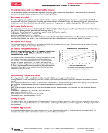
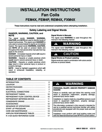
20.02Fan ClutchesGeneral Information132546109D 12VCC78 12V121413B08/11/2005A.B.C.D.11CAf544122To Indicators and GaugesTo Electronic Injectors and Other ActuatorsNormally ClosedNormally Open1. Fan Override Switch2. Air Temperature Sensor3. Engine Speed Sensor4. A/C Pressure Switch5. Coolant Temperature Sensor6. Foot Throttle7. Engine ECM8. Fan Relay (Not in All Systems)9. Solenoid Valve10. Air Supply from Reservoir11. Fan Clutch12. Air Supply to Fan ClutchFig. 2, Engine ECM-Controlled Fan Clutch SchematicThe Horton System Sentry fuse is a brass fitting inthe piston friction disc. The fitting uses lead alloy solder to hold a brass plug. If the fan clutch slips excessively, heat from the slippage will melt the solder andrelease the plug. The melting System Sentry fuse050/4releases air pressure from inside the fan clutch, disengaging the fan clutch to prevent damage to itsbearings.Replacement System Sentry plugs are included in allHorton Advantage repair kits. The replacement plugsCentury Class Trucks Workshop Manual, Supplement 6, September 2004
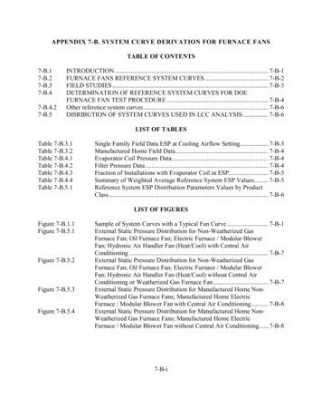
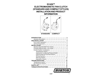
20.02Fan ClutchesGeneral InformationB3241Af200020a07/18/94A. To the circuit breaker1. Fan ClutchB. From the secondary air tank2. Fan-Cycling Switch at the3. Solenoid ValveReceiver-Drier4. Temperature SwitchFig. 3, Fan Clutch Piping and Wiring, Non-ECM Vehicle with Air Conditioningmay be either Allen or Torx, but a Torx tool of theproper size will work to install either type of plug.IMPORTANT: The Horton System Sentry Fuseis left-hand thread; turn it counter-clockwiseto install.IMPORTANT: If a Horton System Sentry fusehas released, determine the cause of the problem and repair it. Do not replace the fuse andput the unit back into service before fixing thecause of the problem.If the fan clutch will not engage, check whether thefuse is melted, and check for other signs and causesof excessive fan clutch slippage.The model number and serial number of a Hortonfan clutch are on the side of the air chamber.Century Class Trucks Workshop Manual, Supplement 6, September 2004050/5
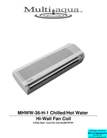
20.02Fan ClutchesGeneral 6.7.8.f544627D. Normally Closed PortAir SupplyE. Air Supply Line toNormally Open PortFan Clutch HubSolenoid ValveThermal Switch (Normally Open System)A/C Pressure Switch (Normally Open System) 12 VoltsManual Override Switch (Normally Open System)Solenoid Valve HousingFan Clutch Hub PulleyFan ClutchFanFig. 4, Fan Clutch Wiring, Non-ECM Vehicle with AirConditioning and Normally Open System3242507/11/20051.2.3.4.5.1f200684Piston Friction DiskCounter BalanceAllen System Sentry FuseTorx System Sentry FuseSystem Sentry Fuse InstalledFig. 5, Horton Advantage Piston Friction Disk, ShowingAllen and Torx Horton System Sentry Fuses050/6Century Class Trucks Workshop Manual, Supplement 6, September 2004
20.02Fan ClutchesFan Clutch Removal and Installation, HortonAdvantageRemovalWARNINGRefer to the following figures for the fan clutch installation for your engine: For Cummins M11 engines, see Fig. 3.Use care when loosening the air line. The linemay be pressurized, and there may be dirt orsludge in the air passages. If quickly disconnected, the line may whip or blow out debris withgreat force, possibly causing eye injury, or otherbodily injury. For Cummins N14 engines, see Fig. 4.2. Disconnect the air line from the fan clutch. For Detroit Diesel Series 50 and 60 engines,see Fig. 5 .3. Remove the fan shroud from the radiator, andmove the shroud back against the engine. Forinstructions, refer to Section 20.01 in this workshop manual. For Caterpillar 3176 engines, see Fig. 1. For Caterpillar 3406 engines, see Fig. 2. For Detroit Diesel Series 55 engines,see Fig. 6.213f20030706/22/951.2.3.4.4Capscrew 3/8–16 x 0.75 inch, grade 8; Lockwasher; WasherFanFan ClutchCapscrew 1/2–13 x 1.25 inch, grade 8; WasherFig. 1, Caterpillar 3176 Engine, Horton Advantage Fan Clutch1. Park the vehicle, apply the parking brakes, andchock the tires.Century Class Trucks Workshop Manual, Supplement 0, January 19964. Disconnect the radiator from all hose andmounts. For instructions, refer to Section 20.01in this workshop manual. With one person holding each side of the radiator, tilt the top of theradiator forward.100/1
20.02Fan ClutchesFan Clutch Removal and Installation, HortonAdvantage241306/22/951.2.3.4.f200308Nut 3/8–16, grade C; WasherFanFan ClutchFan Hub Mounting BoltsFig. 2, Caterpillar 3406 Engine, Horton Advantage Fan Clutch5. With the radiator tilted forward, remove the fan.For instructions, refer to Section 20.01 in thisworkshop manual.2. Install the fan belts. For instructions, refer to theapplicable engine section in Group 01 of thisworkshop manual.6. Remove the fan belts. For instructions, refer tothe applicable engine section in Group 01 of thisworkshop manual.3. Tighten the clutch and hub assembly mountingfasteners 85 lbf·ft (115 N·m ).7. Remove the bolts (or nuts) and washers that attach the fan clutch and hub assembly to the engine. Remove the fan clutch and hub assembly.4. Install the fan. For instructions, refer to Section 20.01 in this workshop manual.5. Install the radiator. For instructions, refer to Section 20.01 in this workshop manual.Installation6. Install the fan shroud. For instructions, refer toSection 20.01 in this workshop manual.1. Position the fan clutch and hub assembly on theengine and install the bolts (or nuts) and washers. Tighten the mounting fasteners just enoughto hold the assembly in place, and allow for fanbelt adjustment.7. Connect the air line to the fan clutch.100/2Century Class Trucks Workshop Manual, Supplement 0, January 1996
20.02Fan ClutchesFan Clutch Removal and Installation, rew 3/8–16 x 1 inch, grade 8; WasherFanFan ClutchScrew, M12 x 1.75 x 90Fan Support BracketFig. 3, Cummins M11 Engine, Horton Advantage Fan ClutchCentury Class Trucks Workshop Manual, Supplement 0, January 1996100/3
20.02Fan ClutchesFan Clutch Removal and Installation, HortonAdvantage2431f20030506/22/951.2.3.4.Capscrew 3/8–16 x 0.75 inch, grade 8; Lockwasher; WasherFanFan ClutchFan Hub Mounting BoltsFig. 4, Cummins N14 Engine, Horton Advantage Fan Clutch100/4Century Class Trucks Workshop Manual, Supplement 0, January 1996
20.02Fan ClutchesFan Clutch Removal and Installation, HortonAdvantage241306/23/951.2.3.4.f200310Capscrew 3/8–16 x 3 inch, grade 8; Lockwasher; WasherFanFan ClutchFlanged Bolt, M12 x 35 mm, grade 10.9; WasherFig. 5, Detroit Diesel Series 50 and 60 Engine, Horton Advantage Fan ClutchCentury Class Trucks Workshop Manual, Supplement 0, January 1996100/5
20.02Fan ClutchesFan Clutch Removal and Installation, ut M14Flanged Bolt M12 x 100mm, grade 10.9Nut 3/8–24; WasherFanFan ClutchFig. 6, Detroit Diesel Series 55 Engine, Horton Advantage Fan Clutch100/6Century Class Trucks Workshop Manual, Supplement 0, January 1996
20.02Fan ClutchesRemoval and Installation, Kysor K22RARemovalNOTE: Protect the radiator fins from damagewhen working on the fan or fan clutch.Typical fan clutch installations are shown in the following figures. The figures do not show all possiblecombinations, but all installations will be similar tothose shown.3. Tilt the top of the radiator forward for room towork. See Section 20.01, Subj. 120. For Caterpillar 3176 engines, see Fig. 1. For Caterpillar 3406 engines, see Fig. 2. For Cummins M11 engines, see Fig. 3.4. With the radiator tilted forward, remove the fan.5. If necessary, remove the fan belts. For instructions, refer to the appropriate engine section inGroup 01.WARNING For Cummins N14 engines, see Fig. 4. For Detroit Diesel Series 50 and 60 engines,see Fig. 5. For Detroit Diesel Series 55 engines, seeFig. 6.To avoid possible personal injury, keep the fanclutch disengaged throughout this procedure bymaintaining between 90 and 120 psi (620 and 830kPa) of air pressure. For Mercedes MBE4000 engines, see Fig. 7.2143f20031306/22/951. Nut, 3/8–24, Grade 5; Washer2. Fan3. Fan Clutch4. Capscrew, M12 x 35, Class 8.8; WasherFig. 1, Caterpillar 3176 Engine, Fan Clutch1. Park the vehicle, turn off the engine, set theparking brake, and chock the tires.6. Apply 90 to 120 psi (620 to 830 kPa) air pressure, to disengage the fan clutch.2. Remove the fan shroud from the radiator, andmove the shroud back against the engine, foraccess to the front of the fan clutch.7. Line up the holes in the front of the fan clutchwith the 5/16-inch Allen screws that hold it to thehub. See Fig. 7.Century Class Trucks Workshop Manual, Supplement 6, September 2004110/1
20.02Fan ClutchesRemoval and Installation, Kysor K22RA234106/22/95f2003151. Nut, 3/8-24, Grade 5; Washer2. Fan3. Fan Clutch4. Fan Clutch Mounting BoltsFig. 2, Caterpillar 3406 Engine, Fan Clutch8. Use a short 5/16-inch Allen bit on a 3/8-inch flexhead ratchet, for best access from the rear of thefan clutch, and remove the 5/16-inch Allenscrews through the holes in the front of the fanclutch housing.2. Install the Allen screws, and tighten them 44 lbf·ft(60 N·m).9. Carefully vent the air pressure from the fanclutch, and allow the fan to engage.5. Install the radiator on the radiator mounts, andconnect all radiator hoses. See Sec. 20.01.10. Remove the fan clutch from the fan clutch hub. Itmay be necessary to gently pry the clutch fromthe hub.6. Install the fan shroud.3. Install the fan belts.4. Install the fan.7. Connect the air line to the fan clutch.8. Remove the chocks from the tires.Installation1. Position the fan clutch on the fan clutch hub, andline up the access holes in the front of the fanclutch with the holes for the Allen screws in thefan clutch hub. See Fig. 8.110/2Century Class Trucks Workshop Manual, Supplement 6, September 2004
20.02Fan ClutchesRemoval and Installation, Kysor K22RA24513f20031606/22/954. Screw, M12 x 1.75 x 905. Fan Support Bracket1. Nut, 3/8-24, Grade 5; Washer2. Fan3. Fan ClutchFig. 3, Cummins M11 Engine, Fan ClutchCentury Class Trucks Workshop Manual, Supplement 6, September 2004110/3
20.02Fan ClutchesRemoval and Installation, Kysor K22RA2431f20031406/22/951. Nut, 3/8-24, Grade 5; Washer2. Fan3. Fan Clutch4. Fan Clutch Mounting BoltsFig. 4, Cummins N14 Engine, Fan Clutch110/4Century Class Trucks Workshop Manual, Supplement 6, September 2004
20.02Fan ClutchesRemoval and Installation, Kysor K22RA243106/22/95f2003121. Nut, 3/8-24, Grade 5; Washer2. Fan3. Fan Clutch4. Flanged Bolt, M12 x 35, Class 10.9; WasherFig. 5, Detroit Diesel Series 50 and 60 Engine, Fan ClutchCentury Class Trucks Workshop Manual, Supplement 6, September 2004110/5
20.02Fan ClutchesRemoval and Installation, K
† The air conditioning refrigerant pressure switch . † Kysor K22RA and Horton DriveMaster fan clutches engage with a spring, and disengage with compressed air. When the fan clutch sole-noid vents air pressure, the sprin