Transcription
EC450TMELECTROMAGNETIC FAN CLUTCH(STANDARD AND COMPACT STYLES)INSTALLATION AND al InformationPRE-INSTALLATIONFan Clutch OperationVehicle PreparationINSTALLATIONStandard Style EC450TM Fan ClutchCompact Style EC450TM Fan ClutchControl System InstallationTemperature SwitchOptional Air Conditioning Pressure SwitchOptional Manual Override SwitchWiring HarnessWarning StickerOperation CheckTROUBLESHOOTINGTemperature SwitchA/C Pressure SwitchPARTS LISTTORQUE SPECIFICATIONS226872233455677889101112121314151
INTRODUCTIONGeneral InformationThis manual describes the correct Fan Clutch Installationprocedures. Following the instructions carefully will provide thesafest and most trouble-free operation.Horton uses the following special notices to give warning ofpossible safety related problems which could cause seriousinjury and provide information to help prevent damage toequipment.Danger is used to indicate the presence of a hazardwhich will cause severe personal injury, death, orsubstantial property damage if the warning is ignored.Warning is used to indicate the presence of a hazardwhich can cause severe personal injury, death, orsubstantial property damage if the warning is ignored.Caution is used to indicate the presence of a hazardwhich will or can cause minor personal injury orproperty damage if the warning is ignored.NOTENote is used to notify people of installation, operation,or maintenance information which is important but nothazard related.222687
PRE-INSTALLATIONYou must follow your company safety practices, which shouldadhere to or be better than Federal or State approvedshop safety practices and procedures. Be sure you haveall the parts listed in the REQUIRED PARTS section (Page14) and that you understand all the procedures andinstructions before beginning work on this unit.Fan Clutch OperationThe EC450TM Fan Clutch is activated by DC voltage fromthe vehicle's electrical system. Multiple control functions canbe used to turn the Fan Clutch on and off, as dictated byyour equipment and operating conditions. All controlfunctions operate the same way: switches close to completethe electrical circuit to engage the fan clutch.The following are the most commonly used control devices: An increase of the engine coolant temperature abovea preset limit causes a normally open (N.O.) thermalswitch in the engine cooling system to close(close-on-rise) at the preset temperature, causing theFan Clutch to engage. An increase of the air conditioner's refrigerant pressureabove a presetlimit causes a normally open(N.O.) refrigerant pressure switch to close, causing theFan Clutch to engage. A manual switch allows you to engage the Fan Clutchat any time.226873
Closure of any of these switches completes the DC circuitto the Fan Clutch. When the circuit is completed, DCcurrent flows through the Fan Clutch coil, causing the FanClutch to engage and the fan to turn. As long as any switchis closed, the Fan Clutch will be engaged.When all switches are open, or power is interrupted for anyreson, the magnetic field collapses, releasing the fan hubfrom the drive pulley. As the field collapses, polarity acrossthe protective diode in the Fan Clutch wiring harnessreverses, making a low-resistance circuit to ground. Thisprotects other electronic components on the vehicle.Vehicle PreparationNOTEIf the vehicle is equipped with air conditioning,always have the A/C refrigerant charge checkedimmediately after installing a Horton EC450TM FanClutch. If the refrigerant pressure is too high, the fanmay run all the time. If the refrigerant pressure istoo low, the low pressure cut-off switch on the vehiclewill disengage the A/C compressor.NOTEUse care to protect the radiator from damage duringthe replacement of the fan clutch.1.Remove the fan assembly and place the fan asidewhile installing the Fan Clutch.2.Remove the fan drive currently on your vehicle.NOTEIf the fan drive you are removing is on a threadedshaft, loosen the hex nut in the same direction asthe engine rotation.422687
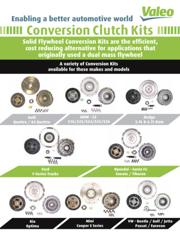
INSTALLATIONStandard StyleEC450TM Fan ClutchNOTEDo not loosen the P-clamp attaching the wiring harness to themetal tab on the Fan Clutch. If loosened, the P-clamp must bere-tightened to prevent the wiring harness from slippingthrough the P-clamp, causing tension on the Fan Clutch wiring.1.2.Install the Horton EC450TM Fan Clutch on the engine. Set thetorque according to the specifications on Page 15.Secure the Anti-rotation Strap to a suitable fixed location onthe engine, such as a retaining bolt or mounting boss. Do notattach to engine wiring harnes tie-downs, etc. Be sure toallow enough slack in the strap to avoid undue stress on themetal tab of the clutch.NOTEMake sure the Anti-rotation Strap and Bracket do not come incontact with any engine components.3.Install the fan onto the Horton EC450TM Fan Clutch. Be surethe fan is installed for the correct rotation. Alternately andevenly tighten the Hex head nuts provided in the kit (See Page15 for Torque Specifications).Anti-rotationStrap226875
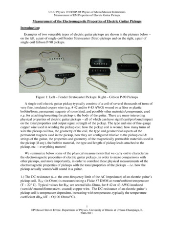
Compact StyleEC450TM Fan Clutch1.Install the fan onto the Horton EC450TM Fan Clutch. Be surethe fan is installed for the correct rotation. Alternately andevenly tighten the Hex head nuts provided in the kit (See Page15 for Torque Specifications).NOTEDo not loosen the P-clamp attaching the wiring harness tothe metal tab on the Fan Clutch. If loosened, the P-clampmust be re-tightened to prevent the wiring harness fromslipping through the P-clamp, causing tension on the FanClutch wiring.2.3.4.5.Install the Fan Clutch on the engine.Feed the Wiring Harness between the radiator and shroud(See Figure ). Trimming of the shroud may be required forproper fit.Secure the P-clamp at the end of the Wiring Harness to theradiator cross-member or a similar suitable location.Be sure the P-clamp is tightly fastened.The Wiring Harness on compact models also functions as ananti-rotation device for the Fan Clutch. It is essential that theP-clamp be tightly secured to an immobile location. However,the Wiring Harness must be allowed enough slack to preventstrain from breaking the tab on the Fan Clutch. Be sure theWiring Harness cannot be pulled into the turning fan.ShroudWiring HarnessCross-memberFan ClutchRadiator622687
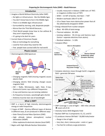
Control System InstallationTemperature Switch1.Drain coolant from the radiator into a clean container. Thecoolant can be returned to the radiator after the TemperatureSwitch is installed.2.Locate a port in the engine in which to install the TemperatureSwitch. The port should be as close to the engine thermostatas possible.3.Use a 3/8" ratchet drive and extension to remove the 1/2" engineplug.NOTEBe careful not to over-torque the Temperature Switch.3.Install and tighten the Temperature Switch in the location wherethe 1/2" threaded plug was removed. Tighten the temperatureswitch to 25 Ft.Lbs. [33.8 N m].4.Replace the coolant.Removal of plug with 3/8"ratchet driveInstallation ofTemperature SwitchStep 2-3To Fan Clutchor SolenoidWiringDiagramTemperatureSwitch226877
Optional Air ConditioningPressure SwitchShrader ValveHortonAir ConditioningPressure SwitchNOTEThe high pressure line maybe equipped with a Shrader valve to prevent refrigerantloss. If a Shrader valve isnot available, you must usea T-fitting (Horton partnumber 994160) to share theShrader valve being usedby the vehicle's highpressure A/C cutoff switch.1.Step 1Install the A/C PressureSwitch onto the male porton the air conditioning linenext to the air conditioningcompressor.Optional Manual OverrideSwitch (Kit #994187)1.2.3.8Manual Override SwitchPull the Manual OverideWiring Harness leads fromthe engine compartmentthrough one of the bulkhead panel's existinggrommets. Leave enoughlength to reach the Switchon dash panel.Install the Manual OverrideSwitch in the dash withineasy reach of the driver'sseat.Cut an opening in the dashfor the Manual OverrideSwitch. Feed the WiringHarness leads through theSwitch opening. AttachWiring Harness leads tothe Switch. Snap theSwitch in place.Wiring HarnessCut OpeningFor ManualOverrideSwitch22687Step 3
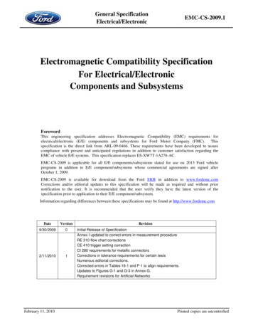
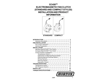
Wiring HarnessRefer to the Wiring Harness illustration andschematic to locate connectors in the WiringHarness installation.1.Feed the power supply end of the WiringHarness from the engine compartment,through the bulkhead, into the cab of thevehicle.2.Plug the spade receptical into the back ofthe ignition switch.NOTECheck to make sure that current is presentat the spade terminal on the IgnitionSwitch when the key is turned to the onposition.If a 12 volt circuit is not available atthe Ignition Switch, a 12 volt fusedcircuit must be located. This circuitmust be energized only when thetruck's Ignition Switch is in the "ON"position. Use caution when selectinga 12 volt power source. Since theEC450 draws 4 amps of current whenengaged, be sure the circuit willhandle this amount of draw along withother devices in the circuit (such asheadlamps, blower motors, etc.).The EC450 Fan Clutch contains aprotective diode which preventsdamage to the vehicle's electricalsystem when the clutch is disengaged.We strongly recommend the use of theHorton Wiring Harness. However, ifyou use a non-Horton Wiring Harness,be sure to observe the correct polarityof the clutch to prevent damage to thediode (See Wiring Diagram).22687Wiring HarnessTo ClutchTo A/CPressureSwitch*To GroundonAlternatorTo ManualOverrideSwitch*ToTemperatureSwitch*To PowerSupply(throughbulkhead toenginecompartment)*All wired the same.Each cut to length forspecific location.Wiring Diagram9
3.Remove the protective cap from the wire connector for theappropriate Temperature Switch location. Plug theconnector into the Temperature Switch connector.4.If the vehicle is equipped with air conditioning, plug in oneof the connectors of the Wiring Harness to the A/C switch.5.If the optional Manual Override Switch is used, plug inone of the open connectors of the Wiring Harness.6.Plug the harness into the Fan Clutch.7.Using the wire ties provided, secure the rest of the WiringHarness away from heat and moving parts.Warning Sticker1.10Install the Fan Clutch warning sticker in a visible area onthe fan shroud.22687
Operation CheckAfter the unit is completely installed, test the Fan Clutch as follows:1.Start the engine and cycle the Fan Clutch on and off 10 to 15 timesusing the Manual Override Switch, or installing a jumper wire acrossthe Temperature Switch Wiring Harness connector. This will seat theclutch faces, insuring maximum life from your Horton Fan Clutch.2.If an A/C Pressure Switch is used, turn the air conditioning onmaximum with the blower fan on high. The fan should engageafter a short period of time due to the air conditioner pressureswitch closing.NOTENormal operating temperature will increase when using an on/offFan Clutch. This type of clutch does not cool the engine untilnecessary. This allows the engine to operate at optimal operatingtemperature. The temperature diagram shows the change in normaloperating temperature range once the Horton EC450 Fan Clutch isinstalled.JumperWireTemperature SwitchWiring HarnessConnectorStep 1Engine TemperatureRange with HortonElectromagneticFan ClutchEngine Temperature Rangewith Direct Drive orViscous DriveHCTemperature Diagram2268711
TROUBLESHOOTINGStay clear of the fan. Fan clutch can engage without warning.Temperature SwitchCheck the Temperature Switch if the Fan Clutch fails to operate after theengine temperature exceeds the Temperature Switch rating.1.Check all wiring terminals.JumperWireFan Clutch Connector PolarityStep 2CStep 22.Unplug the Temperature Switch and use a jumper wire tocomplete the circuit.A. If the Fan Clutch engages, the Temperature Switch may bedefective and should be replaced.NOTEBe sure engine temperature is above the Temperature Switchrating when testing the Temperature Switch. Vehicle gaugesmay not be accurate. The use of an engine thermometer in theinlet of the radiator to sense coolant temperature isrecommended.B. If the Fan Clutch does not engage, the problem is in the FanClutch, the Wiring Harness, or loss of power or ground.C. To check Fan Clutch operation, unplug the Wiring Harness fromthe Fan Clutch and apply power supply voltage to the FanClutch (See Step 2C Polarity Diagram). If the Fan Clutchengages, the problem is in the Wiring Harness, or lack ofpower or ground to the Wiring Harness circuit.1222687
A/C Pressure SwitchIf the air conditioning begins to blow warm air in the cab,there may be a loss of refrigerant, or the Fan Clutch maynot be engaging, drawing air over the condensor to dropthe refrigerant pressure. If the refrigerant pressurebecomes high, the high pressure cut-off switch on thevehicle will disengage the A/C compressor. To check theA/C pressure switch, unplug the A/C pressure switch anduse a jumper wire to complete the circuit.A. If the Fan Clutch engages, the A/C pressure switchmay be defective or the refrigerant charge may betoo low. Have the refrigerant charge checked. Ifnothing is wrong with the refrigerant charge,replace the A/C pressure switch assembly.B.If the Fan Clutch does not engage, the problem is inthe Fan Clutch, the wiring harness, or loss of poweror ground.C.To check the Fan Clutch operation, unplug the wiringharness from the Fan Clutch and apply 12 voltsto Terminal A and ground Terminal B. If the FanClutch engages, the problem is in the wiringharness, or there is a lack of power or ground to theFan Clutch.2268713
PARTS LIST (Required and Optional)PARTDESCRIPTIONQTYREPLACEMENTPART NO.Wiring Harness(12 Volt)*1996125Wiring Harness(24 volt)*1996129TemperatureSwitch*#A/C PressureSwitch11993670 (195oF)993671 (200oF)993672 (205oF)993673 (210oF)996033Pressure Range: 300-210(R12)Thread: 7/16-20 UNF993922Pressure Range: 325-235(R134a)Thread: M10X1.25-6HManual OverrideSwitchwith WiringHarness1Manual OverrideSwitch1A/C PressureSwitchT-fitting19941879944179994160* Required Parts.# See the Horton Medium Duty Fan Clutch Catalog (L-22470) forinformation on selecting the proper Temperature Switches.1422687
TORQUE SPECIFICATIONSMounting Horton EC450TM Fan Clutchto Engine Fan Hub DriveCap Screw SizeMounting Fan toHorton EC450 TM Fan Clutch8 mm10 mm3/8 inchRecommended Torque25-30 ft.-lb. [34-41 N.m]50-60 ft.-lb. [68-81 N.m]40-45 ft.-lb. [54-61 N.m]Mounting Fan to Horton EC450 Fan ClutchStud SizeRecommended Torque10 mm5/16 inch3/8 inch30-35 ft.-lb. [41-47 N.m]18-20 ft.-lb. [24-27 N.m]30-35 ft.-lb. [41-47 N.m]For Technical AssistanceCall the Horton Hotlineat 1-800-621-13202268715
Horton, Inc.2565 Walnut St.Roseville, MN 55113651-361-64001-800-621-1320FAX: 651-361-6801www.hortoninc.comFactory: Britton, SD 57430-0050 1998 Copyright Horton, IncAll rights reserved. Printed in U.S.A.L-22687-A-02991622687
Air Conditioning Pressure Switch Step 1. 22687 9 To Ground on Alternator To Manual Override Switch* *All wired the same. Each cut to length for specific location. Wiring Harness Refer to the Wiring Harness illustration and schematic to locate connectors in the Wiring Harness