Transcription
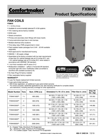
FXM4XProduct SpecificationsFAN COILSFXM4XS 1 1/2 thru 5 tonsS Available for environmentally balanced R 410A systemsS TXV metering device factory installedS ECM motorS Sweat connectionsS Primary and secondary drain fittings with brass insertsS 3 amp automotive type fuse in wire harnessS Multiple electrical entry locationsS Time delay relay (TDR) programmed in motorS Field installed heater packages from 5 kW 30 kW availableseparatelyS HUD approved for manufactured housingS 208/230 1 60 supply voltageS Assembled at the factory compliant with low leak requirementsof less than 2% cabinet leakage rate at 0.5 inches W.C. and1.4% cabinet leakage rate at 0.5 inches W.C. when tested inaccordance with ASHRAE 193 standard.S 1 inch thick insulation with R value of 4.2S Multiposition installation upflow or horizontal left standard,horizontal right with minor modification (field convertible todownflow with available accessory kit)S No Heat (Plug) Kit factory installedS Filter (washable) factory suppliedWARRANTY*Use of the AHRI Certified TM Mark indicates amanufacturer’s participation in the program. Forverification of certification for individual products,go to www.ahridirectory.org .S 5 year No Hassle replacement limited warrantyS 5 year parts limited warranty* With timely registration, an additional 5 year parts limited warrantyFor owner occupied, residential applications only. See warranty certificate for complete detailsand restrictions, including warranty coverage for other applications.Model Number TonsNom. CFM (L/s)Dimensions H x W x D in. (mm)Filter Size in. (mm)Ship Wtlbs. (kg)FXM4X1800**1½600 (283)49 5/8 x 17 5/8 x 22 1/16(1261 x 448 x 560)16 3/8 x 21 1/2(416 x 546)122 (55)FXM4X2400**2800 (378)49 5/8 x 17 5/8 x 22 1/16(1261 x 448 x 560)16 3/8 x 21 1/2(416 x 546)122 (55)FXM4X3000**2½1000 (472)53 7/16 x 21 1/8 x 22 1/16(1357 x 537 x 560)19 7/8 x 21 1/2(505 x 546)146 (66)FXM4X3600**31200 (566)49 5/8 x 21 1/8 x 22 1/16(1261 x 537 x 560)19 7/8 x 21 1/2(505 x 546)157 (71)FXM4X4200**3½1400 (661)49 5/8 x 21 1/8 x 22 1/16(1261 x 537 x 560)19 7/8 x 21 1/2(505 x 546)157 (71)FXM4X4800**41600 (755)53 1/16 x 24 11/16 x 22 1/16(1357 x 627 x 576)23 5/16 x 21 1/2(592 x 546)185 (84)FXM4X6000**52000 (944)59 3/16 x 24 11/16 x 22 1/16(1503 x 627 x 576)23 5/16 x 21 1/2(592 x 546)201 (91)** A Copper Tube, Aluminum Fin EvaporatorAL Aluminum Tube, Aluminum Fin EvaporatorAT Tin Coated Copper Tube, Aluminum Fin EvaporatorSpecifications are subject to change without notice.496 41 5402 04 7/2/19
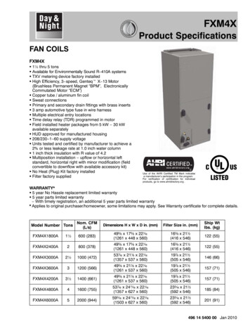
PRODUCT SPECIFICATIONSF Fan CoilFan Coils: FXM4XFAN COIL MODEL NUMBER IDENTIFICATION GUIDEFXM4X1800X ECMLMOTOR TYPEM MultipositionINSTALLATION TYPE4 Environmentally Sound R 410AREFRIGERANTX TXV1800 18,000 BTUH 1 1/2 tons2400 24,000 BTUH 2 tons3000 30,000 BTUH 2 1/2 tons3500 & 3600 36,000 BTUH 3 tons4200 42,000 BTUH 3 1/2 tons4800 48,000 BTUH 4 tons6000 60,000 BTUH 5 tonsA Copper Tube, Aluminum Fin Evaporator CoilAL Aluminum Tube, Aluminum Fin Evaporator CoilAT Tin Coated Copper Tube, Aluminum Fin Evaporator CoilMETERING DEVICENOMINAL CAPACITYSALES CODE / FEATURESACCESSORIES PART NUMBER IDENTIFICATION GUIDEEBAC01NCBAELECTRIC HEATER MODEL NUMBER IDENTIFICATION GUIDEEHK05AKN1EB Evaporator BlowerAC Accessory01 Product Identifier NumberNCB Non Combustible Base KitDFK Down Flow KitPLG Power Plug (no heat kit)SPK Single Point Wiring KitFKS Filter Kit SmallFKM Filter Kit MediumFKL Filter Kit LargeFKX Filter Kit Extra LargeCTK Condensate Trap Kit (PVC pipe)Sales CodeEHK Electric Heater Kit05 5 kW07 7 kW09 9 kW10 10 kW15 15 kW18 18 kW20 20 kW25 25 kW30 30 kWNOMINAL HEAT VALUESales CodeK 208 / 230 single phaseH 208 / 230, 3 phaseKC 208 / 230, supplied as single phase, field convertible to 3 phaseHC 208 / 230 supplied as 3 phase, field convertible to single phaseProduct IdentifierEngineering Code2ASpecifications are subject to change without notice.VOLTAGE (60 Hz)496 41 5402 04
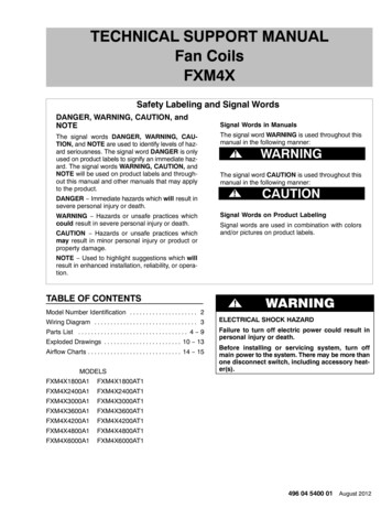
496 41 5402 0422 1/16”7/8”10 3/16”11”3/4”2 1/8” 1”OUTLET AIRSpecifications are subject to change without notice.1”FRONT VIEWACCESSOPENINGD FILTERPANELINLETAIR5”Dimensions Inches (English)SD4874 4 1 AOPENING1/4”1913/16” 2 1/2”ACCESSPANEL 1CONFIG.FORSLOPECOILDETAILSSLOPECOILSRIGHTSIDE VICONNECTIONLOCATIONSSHOWNFOROR IRAND”A”COILSRIGHT DOWNFLOWAPPLICATIONSAPPLICATIONSDISCONNECT ORALLOW 21”SIZESFROM FRONTUNIT NOTE:CONNECTIONALTERNATECIRCUIT BREAKER SUCTION:18 &24 SERVICE 5/8” I.D. SWEATNOTE: MODULARBLOWER, WVOLTAGE30 THRU 36 3/4” I.D. SWEATUNITS WILL HACONTROL WIRING& ELECTRIC HEATERFOR FIELDHIGH VOLTAGESWEAT AIROPTIONALCONVERTEDA TWO PIECEACCESS PANEL 42 THRU 60 7/8” I.D. INLETAPOWERWIRING1 COIL ACCESSCABINETOPPOSITESIDECONDENSATE: 43/4”FPT(SLOPE COIL UNITS ONLY)PANEL11/16”2 5/8”ELIQUID LINE3 CONNECTION1/16”LIQUID LINE LIQUID LINEFITTINGSUCTION LINE CONNECTIONJ HCONNECTIONPANELCONNECTION 1 3/16”19”MODULAR10 7/16”10 3/4”SUCTION LINE9 1/2”1 3/4”CONNECTION6 3/16”TOP VIEWB15/16” C7/8”, 1 3/32”2” DIA. 7/8”DIA.K.O.’S K.O.1 7/8”FOR HIGHVOLTAGEFORLOW VOLTAGE1” WIRING1 15/16”POWERWIRINGCONTROL1 3/8”PRODUCT SPECIFICATIONSFan Coils: FXM4X3
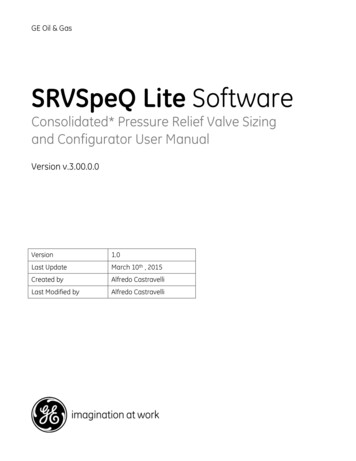
4Specifications are subject to change without notice.3” 1/8Dimensions Inches (English)1”(2 TYP.PLACES)*1 1/2”5 7/8” 1 3/16”1/2”3 1/16”7/16”TYP,1 1/2”2 13/16”5 7/8”7 7/8”(4PLACES)*1/2”4 3/4”5/16” 2TYP.TYP.*1 3/16”3/16”113/16”7 7/8”7/8”8” TYP*TYP.DOWNFLOW(2PLACES)*HORIZ.RIGTYP*(FIELD CONVERTED WITH ACCESSARYKIT)TYP.*YP*HORIZ.LEFT(FIELD CONVERTED WITH ACCESSARY KIT)7/16” TYP.AIRFLOWAIRFLOW2 3/16” TYP.(4 PLACES)(2 PLACES)*1” TYP.GSECONDARY DRAIN PRIMARY DRAI3/4”SECONDARY DRAINF34 1/8”PRIMARY DRAIN(2 PLACES)1 TYP*13/16”PRIMARY DRAINSECONDARY DRSECONDARY DRAIN5/16”PRIMARY DRAINTYP.*AIRFLOWAIRFLOW7/16” TYP.2 3/16” TYP.(2 PLACES)*(2 PLACES)*31/4”1” TYP.PRIMARY DRAINF1 1/4” GPRIMARY DRAINSECONDARY DRAIN(2 PLACES)*PRIMARY DRAIN1 13/16”5/16”SECONDARY DRAINTYP.*TYP.*PRIMARY DRAIN2 7/8”5/16”7/16”TYP.1 1/4”1”PLACES)*TYP.1 1/4”TYP.*1 4”23/16”TYP.*2 7/8”FDOWNFLOW(2 TYP.PLACES)*7/8”TYP.*HORIZ.LEFTTYP.*(FIELD CONVERTED WITH ACCESSARY KIT) (FIELD CONVERTED WITH ACCESSARY KIT)TYP.*PRODUCT SPECIFICATIONSFan Coils: FXM4X496 41 5402 04
496 41 5402 04BC54.0560.4258.8 279.4 22.219.025.4 OUTLET AIRSpecifications are subject to change without notice.FRONT VIEW127.0 FILTER ACCESS25.4 OPENINGD PANELINLETAIRDimensions MM (SI Metric)OPENING503.2ACCESSPANEL 31.8CONFIG. IONLOCATIONSSHOWNFOROR HORIZ.DOWNFLOWORHORIZ.LEFTUPFLOWAPPLICATIONSINLET AIRAND”A”COILSRIGHT DOWNFLOWAPPLICATIONSAPPLICATIONSDISCONNECT ORALLOW 533.4FROM FRONTUNITNOTE:CONNECTIONSIZESALTERNATECIRCUIT : 18 & 24 15.88 I.D. SWEAT22.23, 27.78,50.80DIALOCATIONFORLOW VOLTAGE& ELECTRIC HEATERCONTROLWIRINGUNITSWILLHA30 THRU 36 19.05 I.D. SWEAT OPTIONALFOR FIELDHIGH VOLTAGECONVERTEDACCESS PANEL 42 THRU 60 22.23 I.D.INLETA TWO GCOILACCESS9.53 I.D. SWEATCABINETLIQUID:OPPOSITESIDE(SLOPE COIL UNITS ONLY)PANEL66.7CONDENSATE: 119.119.0 FPTELIQUID LINE 77.8CONNECTIONLIQUID LINEFITTINGLIQUID LINESUCTION LINE CONNECTIONJ HCONNECTIONPANELCONNECTION 30.2482.6MODULA265.1273.0 SUCTION LINE241.344.4CONNECTION157.223.822.23, 27.7850.80 DIA.47.622.23K.O.’SDIA. K.O.FOR HIGHVOLTAGEFOR LOW PRODUCT SPECIFICATIONSFan Coils: FXM4X5
Specifications are subject to change without notice.79.4AIRFLOW11.1 TYP.AIRFLOW55.6 TYP.(4 PLACES)(2 PLACES)*25.4 TYP.GSECONDARY DRAIN PRIMARY DRAISECONDARY DRAINF120.6(2 PLACES)PRIMARY DRAIN79.4PRIMARY DRAINSECONDARY DRSECONDARY46.0DRAIN8.0PRIMARY DRAINTYP*TYP.*A COILDimensions MM (SI Metric)25.4 TYP.38.1(2 PLACES)*149.277.8 71.438.1 149.230.2 12.7200.012.7120.6TYP.*8.030.2200.02.2 TYP*DOWNFLOW46.0HORIZ.KIT)RIGTYP*(FIELD CONVERTED WITH ACCESSARY(FIELDCONVYP*HORIZ.LEFTTYP.(FIELD CONVERTED WITH ACCESSARY KIT)6AIRFLOWAIRFLOW11.1 TYP.55.6 TYP.(2 PLACES)*(2 PLACES)*82.625.4 TYP.PRIMARY DRAINF 31.8GPRIMARY DRAINSECONDARY DRAIN(2 PLACES)*PRIMARY DRAIN46.08.0SECONDARY DRAINTYP.*TYP.*PRIMARY DRAIN73.08.011.1TYP.31.825.4TYP.31.8TYP.*31.8 65.1 YP.*HORIZ.LEFTTYP.*(FIELDCONVERTEDWITH ACCESSARY KIT)(FIELD CONVERTED WITH ACCESSARY KIT)TYP.*SLOPE COILPRODUCT SPECIFICATIONSFan Coils: FXM4X496 41 5402 04
PRODUCT SPECIFICATIONSFan Coils: FXM4XDIMENSIONAL DATA (refer to drawings on previous 000Dimensions 83/83/8Ship.Weight ��A”“A”“A”“A”DIMENSIONAL DATA (refer to drawings on previous 000Dimensions 9587587684829J432432483 p.Weight(kg)55556671718491PHYSICAL DATAModel Size1800240030003600420048006000600 (283)800 (378)1000 (472)1200 (566)1400 (661)1600 (755)2000 (944)1/23/43/4Blower DataCFM nominal (L/s)Motor TypeECMHP1/31/31/21/2Filter Data (factory supplied, washable)16 3/8 x 21 1/2(416 x 546)Filter Size in. (mm)19 7/8 x 21 1/2(505 x 546)23 5/16 x 21 1/2(592 x 546)Coil Data (all coils 14½ fins per inch, wavy lanced bare aluminum fin)Face Area ft2 (m2)2.97 (0.28)2.97 (0.28)3.46 (0.32)4.45 (0.41)5.93 (0.55)7.42 (0.69)Refrigerant Line Connections (sweat)Liquid inch (mm)3/8 (10)3/8 (10)3/8 (10)3/8 (10)3/8 (10)3/8 (10)3/8 (10)Suction inch (mm)5/8 (16)5/8 (16)3/4 (19)3/4 (19)7/8 (22)7/8 (22)7/8 (22)496 41 5402 04Specifications are subject to change without notice.7
PRODUCT SPECIFICATIONSFan Coils: FXM4XELECTRICAL DATA, FAN COIL ONLY WITHOUT ELECTRIC 4200FXM4X4800FXM4X6000Motor Full LoadAmps (FLA)2.82.84.14.14.16.06.0208/230V, single phase, 60 HzMinimum CircuitMaximum Fuse/Ckt Bkr AmpsAmpacity (MCA)(Max OverCurrent Protection MOCP)3.5153.5155.1155.1155.1157.5157.515AIRFLOW PERFORMANCE CFM at a given Speed and Static M4X4200FXM4X4800FXM4X6000Blower SpeedTap 5Tap 4Tap 3Tap 2Tap 1Tap 5Tap 4Tap 3Tap 2Tap 1Tap 5Tap 4Tap 3Tap 2Tap 1Tap 5Tap 4Tap 3Tap 2Tap 1Tap 5Tap 4Tap 3Tap 2Tap 1Tap 5Tap 4Tap 3Tap 2Tap 1Tap 5Tap 4Tap 3Tap 2Tap 71757166416641459130120301811181116651462Static Pressure, inlet to outlet (inches water TES:1. Airflow based upon dry coil at 230v with factory approved filter and electric heater (2 element heater sizes 18 through 36, 3 element heater sizes42 through 60).2. Airflow at 208 volts is approximately the same as 230 volts because the X13 motor is a constant torque motor. The torque doesn’t drop off at thespeeds the motor operates.3. To avoid potential for condensate blowing out of drain pan prior to making drain trap: Return static pressure must be less than 0.40 in. wc. Horizontal applications of 042 060 sizes must have supply static greater than 0.20 in. wc.4. Airflow above 400 cfm/ton on 048 060 size could result in condensate blowing off coil or splashing out of drain pan.5. Shading Airflow outside 450 cfm/ton.8Specifications are subject to change without notice.496 41 5402 04
PRODUCT SPECIFICATIONSFan Coils: FXM4XSTATIC PRESSURE DROP ACROSS FILTER (inches of water column)400.020 Model Size1800240030003600420048006000600.044.022.022 800.075.048.048 1000 .072.072.051.051.051 CFM1200 .100.100.070.070.070 1400 .092.092.092 1600 .120.120.120.0861800 .152.152.152.1052000 .130STATIC PRESSURE CORRECTION FROM DRY TO WET COIL (inches of water column)Airflow performance chart was developed using fan coils with DRY coils.When taking a static reading across a WET coil, adjust the static pressure numbers by adding the values in this table(for a given CFM, wet coil will have greater static pressure drop than dry coil).CFM500600700800900 1000 1100 1200 1300 1400 1500 1600 1700 1800 1900 2000Model Size1800.034 .049 .063 2400.016 .027 .038 .049 .059 3000 .049 .059 .070 .080 3600 .055 .064 .073 .081 4200 .049 .056 .063 .070 4800 .038 .043 .049 .054 .059 6000 .027 .031 .035 .039 .043STATIC PRESSURE CORRECTION FOR ELECTRIC HEATERS (inches of water column)Airflow performance chart was developed using fan coils with 10 kW electric heater (2 elements) in the 1800 3600 modelsizes, and 15 kW electric heaters (3 elements) in the 4200 6000 model sizes.When using a different number of heater elements, adjust the static pressure numbers by adding or subtracting the valuesin this table (for a given CFM, more electric heater elements create higher static pressure drop).Heater kWNo Heater3 or 58 or 109 or 1520Number of Heat Elements01234Model Size1800 0.02 0.010 0.02 0.042400 0.02 0.010 0.02 0.043000 0.02 0.010 0.02 0.043600 0.02 0.010 0.02 0.044200 0.04 0.020 0.024800 0.04 0.020 0.026000 0.04 0.020 0.02ESTIMATED SOUND POWER LEVEL (dBA)ConditionsModel 40016002000Ext StaticPressure0.250.250.250.250.250.250.25Octave Band Center 045.747.048.048.849.450.051.0* Estimated sound power levels have been derived using the method described in the 1987 ASHRAE HVAC Systems & ApplicationsHandbook, Ch 52, pg 52.7.496 41 5402 04Specifications are subject to change without notice.9
10Specifications are subject to change without 25.0——————————L3,L4Dual CircuitMin Ampacity /66/6——6/66/6——————————L1, �—————L3, L4Dual CircuitMin Wire Size (AWG)208/230V 9/32.036.2/40.0L3, L428.9/32.036.2/40.0L5, L644.7/48.553.8/58.5L1, L236.2/40.045.3/50.0L3, L436.2/40.045.3/50.0L5, L6Minimum Circuit Ampacity208/230V k8/86/6L1, L28/88/8L3, L48/88/8L5, L6Minimum Wire Size (AWG)208/230V}10/1010/10Min GndWire ——————————L1, 0L1, L240/4050/50L3, L440/4050/50L5, �——L3,L4Dual CircuitMax Wire Length208/230V (Ft)‡‡59/6078/80L1, L273/7359/59L3, L473/7359/59L5, L6Max Wire Length 25——————————L3,L4Dual CircuitMax Fuse/Ckt Bkr Amps208/230VMax Fuse/Ckt Bkr ——————————L3,L4Dual CircuitMin Gnd Wire Size208/230VBRANCH CIRCUITFIELD MULTIPOINT WIRING OR 24 AND 30 KW SINGLE 36.2/40.0——————————L1,l2Dual CircuitHEATER AMPS208/230VHeater Amps 208/230VL1, L2FuseFuseFuseFuseCkt BkrFuseNoneNoneCkt BkrFuseCkt BkrNoneNoneNoneCkt BkrNoneCkt BkrCkt BkrNoneNoneINTERNALCIRCUITPROTECTIONNotes:1Copper wire must be used. If other than uncoated (non-plated), 75 C ambient, copper wire (solid wire for 10 AWG and smaller, stranded wire for larger than 10 AWG) is used, consult applicable tables of the NationalElectric Code (ANSI/NFPA 70).* When used with Fan Coil model sizes 2400, 3600.** When used with Fan Coil model sizes 4200, 4800, 6000.k Includes blower motor amps of largest Fan Coil used with heater.{ Supplied as single phase, field convertible to 3-phase.} Supplied as 3-phase, field convertible to single phase, single or multiple supply circuits.}} Length shown is as measured one way along wire path between unit and service panel for a voltage drop not to exceed 2%.EHK25AHCF}EHK30AHCF}11.311131111111PHASEHeater 85103.8208v5230vHeater AKBHeater ModelHeater kWELECTRIC HEATER ELECTRICAL DATAPRODUCT SPECIFICATIONSFan Coils: FXM4X496 41 5402 04
PRODUCT SPECIFICATIONSFan Coils: FXM4XACCESSORIESPart NumberEBAC01DSCDescriptionUse with model sizeuse with All single phase Heaters5 kW thru 10 kWDisconnect KitEBAC02NCBEBAC03NCB1800, 24003000, 3600, 4200Downflow Base KitEBAC04NCB4800, 6000EBAC01DFSDownflow Conversion Kit Slope CoilEBAC02DFADownflow Conversion Kit “A” CoilEBAC01SPKSingle Point Wiring Kitonly for use with 15 kW & 20 kW fused heatersSingle Point Wiring Kit Square DrJumper Bar AssemblyOnly for use withEHK15AKB and EHK20AKB breaker heatersSquare Dr part #QOU14100JBAF *EBAC01FKMEBAC01FKLEBAC01FKX1800, 2400, 30003600, 4200, 4800, 60001800, 2400Filter Kit (washable, box of 12)Factory Supplied3000, 3600, 42004800, 6000NASA00201FRStandard Filter Rack (16 x 20 x 1 filter required)1800, 2400NASA00301FRStandard Filter Rack (20 x 20 x 1 filter required)3000, 3600, 4200NASA00401FRStandard Filter Rack [quantity 2](12 x 20 x 1 filter required)EBAC01PLGNo Heat (Plug) Kit (box of 6)EBAC01CTKPVC Condensate Trap Kit (box of 50)EBAC01GSKHorizontal Gasket Kit4800, 6000Factory InstalledALLALL(required for horizontal right and , 2400, 3000, 3600, 42004800TXV Kit, R 22, Copper or Tin Coil OnlyNAEA20301TX6000NAEB20101TX1800AL, 2400AL, 3000AL, 3600AL, 4200ALNAEB20201TX4800ALTXV Kit, R 22, Aluminum Coil OnlyNAEB20301TX11911406000ALDoor Gasket Kit **All* Square D part number given for reference only. Check with local Square D supplier.** This kit is for replacement of factory installed
FOR HIGH VOLTAGE POWER WIRING OPPOSITE SIDE INLET AIR INLET AIR INLET AIR OUTLET AIR 7/8”DIA. K.O. FOR LOW VOLTAGE CONTROL WIRING 7/8”, 1 3/32” 2” DIA. K.O.’S FOR HIGH VOLTAGE POWER WIRING OPENING H J UNIT CONNECTION SIZES PRODUCT SPECIFICATIONS Fan Coils: FXM4X 496 41 5402