Transcription
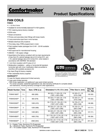
FXM4XLY SOUNDTALREENNERA TIGFRProduct SpecificationsENVIRONMFAN COILSFXM4XS 1½ thru 5 tonsS Available for Environmentally Sound R 410A systemsS TXV metering device factory installedS High Efficiency, 3 speed, Genteqt X 13 Motor(Brushless Permanent Magnet “BPM”, ElectronicallyCommutated Motor “ECM”)S Copper tube / aluminum fin coilS Sweat connectionsS Primary and secondary drain fittings with brass insertsS 3 amp automotive type fuse in wire harnessS Multiple electrical entry locationsS Time delay relay (TDR) programmed in motorS Field installed heater packages from 5 kW 30 kWavailable separatelyS HUD approved for manufactured housingS 208/230 1 60 supply voltageS Units tested and certified by manufacturer to achieve a2% or less leakage rate at 1.0 inch water columnS 1 inch thick insulation with R value of 4.2S Multiposition installation upflow or horizontal leftstandard, horizontal right with minor modification (fieldconvertible to downflow with available accessory kit)S No Heat (Plug) Kit factory installedS Filter factory suppliedUse of the AHRI Certified TM Mark indicatesa manufacturer’s participation in the program.For verification of certification for individualproducts, go to www.ahridirectory.org .WARRANTY*S 5 year No Hassle replacement limited warrantyS 5 year parts limited warranty With timely registration, an additional 5 year parts limited warranty* Applies to original purchaser/homeowner, some limitations may apply. See Warranty certificate for complete details.Model Number TonsNom. CFM(L/s)Dimensions H x W x D in. (mm)Filter Size in. (mm)Ship Wtlbs. (kg)FXM4X1800A1½600 (283)49s x 17s x 22z(1261 x 448 x 560)16a x 212(416 x 546)122 (55)FXM4X2400A2800 (378)49s x 17s x 22z(1261 x 448 x 560)16a x 212(416 x 546)122 (55)FXM4X3000A2½1000 (472)53v x 218 x 22z(1357 x 537 x 560)19d x 212(505 x 546)146 (66)FXM4X3600A31200 (566)49s x 218 x 22z(1261 x 537 x 560)19d x 212(505 x 546)157 (71)FXM4X4200A3½1400 (661)49s x 218 x 22z(1261 x 537 x 560)19d x 212(505 x 546)157 (71)FXM4X4800A41600 (755)53v x 24n x 22z(1357 x 627 x 560)23c x 212(592 x 546)185 (84)FXM4X6000A52000 (944)59x x 24n x 22z(1503 x 627 x 560)23c x 212(592 x 546)201 (91)496 14 5400 00 Jan 2010
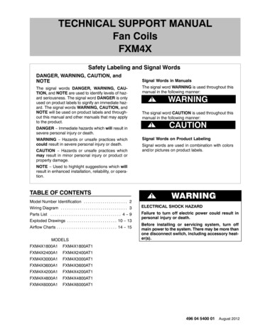
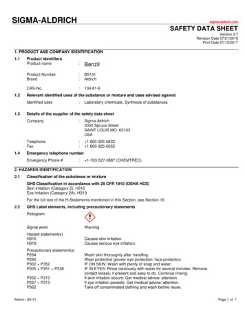
PRODUCT SPECIFICATIONSFan Coils: FXM4XCLEARANCES AND UNIT DIMENSIONS( OPENING)FBAEHGC(SERVICEACCESS)D( OPENING)38 11 82REQUIRED CLEARANCES ALL MODELS inches (mm)NoAll Sides0HeatersFrom Supply Duct0All Sides0WithFrom First 3 feet of Supply Duct to Combustibles 1 (25)HeatersFrom Supply Duct to Combustibles after 3 feet02Unit w22wB11111111111111C19m19m19m19m19m19m19mFXM (inches)DE15s22z15s22z19822z19822z19822z22n 22z22n 49s49s53v59xUnit M 113571261126113571503496 14 5400 00
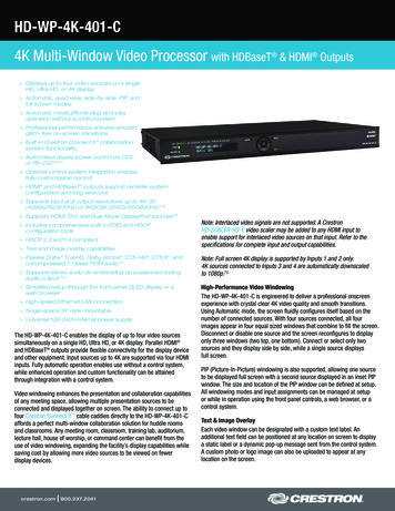
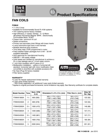
PRODUCT SPECIFICATIONS496 14 5400 007/8”, 1 3/32”2” DIA. 7/8”DIA.K.O.’S K.O.1 7/8”FOR HIGHVOLTAGEFORLOW VOLTAGE1” WIRING1 15/16”POWERWIRINGCONTROL1 3/8”TOP VIEWB15/16” C22 1/16”7/8”10 3/16”11”1”3/4”2 1/8”OUTLET AIRDISCONNECT ORALLOW 21”SIZESFROM FRONTUNIT NOTE:CONNECTIONALTERNATECIRCUIT BREAKER SUCTION:18&24 5/8”NOTE: MODULARBLOWER, CONTROL,FOR SERVICE I.D. SWEAT7/8”,1 3/32”,2”DIA. K.LOCATIONFORLOWVOLTAGE30THRU36 3/4”I.D.SWEATUNITS WILL HACONTROL WIRING& ELECTRIC HEATERFOR FIELDHIGH VOLTAGE42THRU60 7/8”I.D.SWEATOPTIONALCONVERTEDA TWO PIECEACCESS PANELINLET AIRAPOWERWIRING1 1/2”LIQUID:3/8”I.D.SWEATRIGHT SIDE RETURNOPENINGCOIL ACCESSCABINETSIDEONLY)CONDENSATE: 43/4”FPT(SLOPEOPPOSITECOIL UNITSPANEL11/16”2 NGLIQUID LINESUCTION LINE CONNECTIONJ HCONNECTIONPANELCONNECTION 1 3/16”19”MODULAR10 7/16”10 3/4”SUCTION LINE9 1/2”1 3/4”CONNECTION6 3/16”ACCESSOPENINGD FILTERPANELINLETAIRFRONT VIEWOPENING1/4”1913/16” 2 1/2”ACCESSPANEL 1CONFIG.FORSLOPECOILDETAILSSLOPECOILSRIGHTSIDE VICONNECTIONLOCATIONSSHOWNFOROR HORIZ.DOWNFLOWORHORIZ.LEFTUPFLOWAPPLICATIONSINLET AIRAND”A”COILSRIGHT DOWNFLOWAPPLICATIONSAPPLICATIONS3SD4874 4 1 ADimensions Inches (English)Fan Coils: FXM4X1”5”
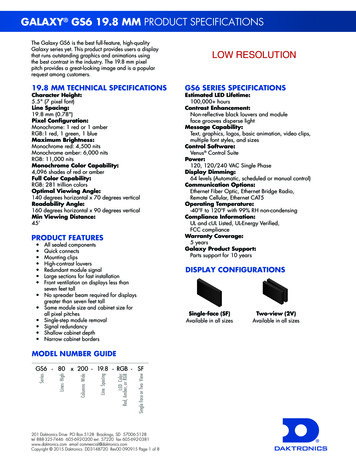
PRODUCT SPECIFICATIONS4AIRFLOWAIRFLOW7/16” TYP.2 3/16” TYP.(2 PLACES)*(2 PLACES)*1” TYP. 3 1/4”PRIMARY DRAINF1 1/4” GPRIMARY DRAINSECONDARY DRAIN(2 PLACES)*PRIMARY DRAIN1 13/16”5/16”SECONDARY DRAINTYP.*TYP.*PRIMARY DRAIN2 7/8”5/16”7/16”TYP.1 1/4”TYP.1 1/4”TYP.*1 1/4”(4PLACES)*2 3/16”TYP.*2 TYP.*(FIELDCONVERTEDWITH ACCESSARY KIT) (FIELD CONVERTED WITH ACCESSARY KIT)TYP.*7/16” TYP.AIRFLOWAIRFLOW2 3/16” TYP.(4 PLACES)(2 PLACES)*1” TYP.GSECONDARY DRAIN PRIMARY DRAI3/4”SECONDARY DRAINF34 1/8”PRIMARY DRAIN(2 PLACES)1 TYP*13/16”PRIMARY DRAINSECONDARY DRSECONDARY DRAIN5/16”PRIMARY DRAINTYP.*1”(2 TYP.PLACES)*1 1/2”5 7/8” 1 3/16”1/2”3 1/16”7/16”TYP,1 1/2”213/16”57/8”7 7/8”(4PLACES)*1/2”43/4”5/16”TYP.*1 3/16”2TYP.3/16”113/16”7 7/8”7/8”8” TYP*TYP.DOWNFLOWHORIZ.RIGTYP* (2 PLACES)*(FIELD CONVERTED WITH ACCESSARYKIT)TYP.*YP*HORIZ.LEFT(FIELD CONVERTED WITH ACCESSARY KIT)3” 1/8Fan Coils: FXM4X496 14 5400 00Dimensions Inches (English)
PRODUCT SPECIFICATIONS496 14 5400 0022.23, 27.7850.80 DIA.47.622.23K.O.’SDIA. K.O.FOR HIGHVOLTAGEFOR LOW VOLTAGE25.449.2POWERWIRINGCONTROL34.9WIRING23.8TOP VIEWBC54.0560.4258.8 279.4 22.219.025.4 OUTLET AIRDISCONNECT ORALLOW 533.4FROM FRONTUNITNOTE:CONNECTIONSIZESALTERNATECIRCUIT : 18 & 24 15.88 I.D. SWEAT22.23, 27.78,50.80DIALOCATIONFORLOWVOLTAGE& ELECTRIC HEATERCONTROLWIRINGUNITS WILL HA30 THRU 36 19.05 I.D. SWEAT OPTIONALFOR FIELDHIGH VOLTAGECONVERTEDACCESS PANEL 42 THRU 60 22.23 I.D.INLETA TWO PIECESWEATAIRWIRINGA POWER38.1RIGHTSIDE RETURNOPENINGCOILACCESSCABINETLIQUID: 9.53 I.D. SWEATOPPOSITESIDE(SLOPE COIL UNITS ONLY)PANEL66.7CONDENSATE: 119.119.0 FPTELIQUID LINE 77.8CONNECTIONLIQUID LINEFITTINGLIQUID LINESUCTION LINE CONNECTIONJ HCONNECTIONPANELCONNECTION 30.2482.6MODULA265.1273.0 SUCTION LINE241.344.4CONNECTION157.2FRONT VIEWOPENING503.2ACCESSPANEL 31.8CONFIG. IONLOCATIONSSHOWNFORUPFLOWORHORIZ.DOWNFLOW ANDOR HORIZ.LEFT APPLICATIONSINLET AIR”A”COILSRIGHT DOWNFLOWAPPLICATIONSAPPLICATIONS5Dimensions MM (SI Metric)Fan Coils: FXM4X127.0 FILTER ACCESS25.4 OPENINGD PANELINLET AIR
AIRFLOWAIRFLOW11.1 TYP.55.6 TYP.(2 PLACES)*(2 PLACES)*25.4 TYP. 82.6PRIMARY DRAINF 31.8GPRIMARY DRAINSECONDARY DRAIN(2 PLACES)*PRIMARY DRAIN46.08.0SECONDARY DRAINTYP.*TYP.*PRIMARY DRAIN73.08.011.1TYP.31.825.4TYP.31.8TYP.*31.8 65.1 YP.*HORIZ.LEFTTYP.*(FIELDCONVERTEDWITH ACCESSARY KIT)(FIELD CONVERTED WITH ACCESSARY KIT)TYP.*PRODUCT SPECIFICATIONS6SLOPE COILAIRFLOW11.1 TYP.AIRFLOW55.6 TYP.(4 PLACES)(2 PLACES)*25.4 TYP.GSECONDARY DRAIN PRIMARY DRAISECONDARY DRAINF120.6(2 PLACES)PRIMARY DRAIN79.4PRIMARY DRAINSECONDARY DRSECONDARY46.0DRAIN8.0PRIMARY DRAINTYP*TYP.*79.4A COILDimensions MM (SI Metric)Fan Coils: FXM4X496 14 5400 0025.4 TYP.38.1(2 PLACES)*149.277.8 71.438.1 149.230.2 12.7200.012.7120.6TYP.*8.030.2200.02.2 TYP*DOWNFLOW46.0HORIZ.KIT)RIGTYP*(FIELD CONVERTED WITH DWITH ACCESSARY KIT)
PRODUCT SPECIFICATIONSFan Coils: FXM4XDIMENSIONAL DATA (refer to drawings on previous pages)Dimensions ½33½45 (s (s%#v (s s!(8!(8!(8@ n@ nEFG!%a @#8 @#s!%a @#8 @#s!(x @ , @&2!%n @#v @#8!%n @#v @#8@@n !(2@&4 @ ,@@n @%4 #@, #@sHJ-171719-Ship.CoilWeightSuct. Liquid Type (lbs)saSlope 122saSlope 122waSlope 1DIMENSIONAL DATA (refer to drawings on previous pages)Dimensions 9587587684829-432432483-Ship.CoilWeightSuct. Liquid Type(kg)1610 Slope551610 Slope551910 “A”91PHYSICAL DATAModel Size180024003000360042004800TXV factory installed, hard shut off, bi flow type for heat pump applicationFXM4X4 ton3 ton4 tonBlower DataCFM 566)(661)(755)Motor TypeHPFilter DataFilter Size in. (mm)1/31/3Genteqt X 13 (BPM, ECM)1/21/21/216a x 212(416 x 546)19d x 212(505 x 546)496 14 5400 003/8 (10)5/8 (16)3/8 (10)3/4 (19)3/8 (10)3/4 (19)2000(944)3/423c x 212(592 x 546)Coil Data (all coils 14½ fins per inch, wavy lanced bare aluminum fin)Face Area ft2 erant Line Connections (sweat)Liquid inch (mm)3/8 (10)Suction inch (mm)5/8 (16)3/460003/8 (10)7/8 (22)5.93(0.55)7.42(0.69)3/8 (10)7/8 (22)3/8 (10)7/8 (22)7
PRODUCT SPECIFICATIONSFan Coils: FXM4XELECTRICAL DATA, FAN COIL ONLY WITHOUT ELECTRIC 4200FXM4X4800FXM4X6000Motor Full LoadAmps (FLA)2.82.84.14.14.16.06.0208/230V, single phase, 60 HzMinimum CircuitMaximum Fuse/Ckt Bkr AmpsAmpacity (MCA)(Max OverCurrent Protection MOCP)3.5153.5155.1155.1155.1157.5157.515AIRFLOW PERFORMANCE CFM at a given Speed and Static M4X4200FXM4X4800FXM4X6000Blower SpeedTap 5Tap 4Tap 3Tap 2Tap 1Tap 5Tap 4Tap 3Tap 2Tap 1Tap 5Tap 4Tap 3Tap 2Tap 1Tap 5Tap 4Tap 3Tap 2Tap 1Tap 5Tap 4Tap 3Tap 2Tap 1Tap 5Tap 4Tap 3Tap 2Tap 1Tap 5Tap 4Tap 3Tap 2Tap 1Measured Static Pressure, inlet to outlet (inches water 071453146214181371132712781228NOTES:1. Airflow based upon dry coil at 230v with factory approved filter and electric heater (2 element heater sizes 18 through 36, 3 element heatersizes 42 through 60).2. Airflow at 208 volts is approximately the same as 230 volts because the X13 motor is a constant torque motor. The torque doesn’t drop off atthe speeds the motor operates.3. To avoid potential for condensate blowing out of drain pan prior to making drain trap: Return static pressure must be less than 0.40 in. wc.Horizontal applications of 043 061 sizes must have supply static greater than 0.20 in. wc.4. Airflow above 400 cfm/ton on 049 061 size could result in condensate blowing off coil or splashing out of drain pan.5. Shading Airflow outside 450 cfm/ton.8496 14 5400 00
PRODUCT SPECIFICATIONSFan Coils: FXM4XSTATIC PRESSURE DROP ACROSS FILTER (inches of water column)Model Size1800240030003600420048006000400.020 600.044.022.022 800.075.048.048 1000 .072.072.051.051.051 CFM1200 .100.100.070.070.070 1400 .092.092.092 1600 .120.120.120.0861800 .152.152.152.1052000 .130STATIC PRESSURE CORRECTION FROM DRY TO WET COIL (inches of water column)Airflow performance chart on pages NO TAG NO TAG was developed using fan coils with DRY coils.When taking a static reading across a WET coil, adjust the static pressure numbers on pages NO TAG NO TAG byadding the values in this table (for a given CFM, wet coil will have greater static pressure drop than dry coil).CFMModel Size500 600 700 800 900 1000 1100 1200 1300 1400 1500 1600 1700 1800 1900 20001800.034 .049 .063 2400.016 .027 .038 .049 .059 3000 .049 .059 .070 .080 3600 .055 .064 .073 .081 4200 .049 .056 .063 .070 4800 .038 .043 .049 .054 .059 6000 .027 .031 .035 .039 .043ACCESSORIESDescriptionDisconnect KitDownflow Base KitDownflow Conversion Kit Slope CoilDownflow Conversion Kit “A” CoilSingle Point Wiring KitSingle Point Wiring Kit Square DrJumper Bar AssemblyPart BEBAC01DFSEBAC02DFAEBAC01SPKAMFK20SPA orSquare Dr part #QOU14100JBAFNo Heat (Plug) Kit (box of 6)PVC Condensate Trap Kit (box of rizontal Gasket KitEBAC01GSKPermanent Filter Kit (box of 12)496 14 5400 00Use with model sizeuse with All Heaters 5 kW thru 10 kW18002400, 30003600, 4200, 480060001800, 2400, 30003600, 4200, 4800, 6000only for use with 15 kW & 20 kW fused heatersOnly for use withEHK15AKB and EHK20AKB breaker heaters1800, 24003000, 3600, 42004800, 6000Factory InstalledALLALL(required for horizontal right and downflow)9
PRODUCT SPECIFICATIONSFan Coils: FXM4XELECTRIC HEATERSPart AKFEHK20AKBEHK25AHCFEHK30AHCFDescription5 kW, single phase, no internal circuit protection5 kW, single phase, with circuit breakers8 kW, single phase, no internal circuit protection8 kW, single phase, with circuit breakers9 kW, supplied as single phase, field convertible to3 phase, no internal circuit protection10 kW, single phase, no internal circuit protection10 kW, single phase, with circuit breakers15 kW, single phase, with fuses15 kW, single phase, with circuit breakers15 kW, 3 phase, no internal circuit protection18 kW, 3 phase, no internal circuit protection20 kW, single phase, with fuses20 kW, single phase, with circuit breakers24 kW, supplied as 3 phase, field convertible tosingle phase, with fuses30 kW, supplied as 3 phase, field convertible tosingle phase, with fusesUse with Model SizesALLALLALLALL3600, 4200, 4800, 6000ALLALL2400, 3000, 3600, 4200, 4800, 60002400, 3000, 3600, 4200, 4800, 60003600, 4200, 4800, 60004200, 4800, 60003000, 3600, 4200, 4800, 60003000, 3600, 4200, 4800, 60004800, 60004800, 6000STATIC PRESSURE CORRECTION FOR ELECTRIC HEATERS (inches of water column)Airflow performance chart on pages NO TAG NO TAG was developed using fan coils with 10 kW electric heater (2elements) in the 1800 3600 model sizes, and 15 kW electric heaters (3 elements) in the 4200 6000 model sizes.When using a different number of heater elements, adjust the static pressure numbers on pages NO TAG NO TAGby adding or subtracting the values in this table (for a given CFM, more electric heater elements create higher staticpressure drop).Heater kWNo Heater3 or 58 or 109 or 1520Number of Heat Elements01234Model Size1800 0.02 0.010 0.02 0.042400 0.02 0.010 0.02 0.043000 0.02 0.010 0.02 0.043600 0.02 0.010 0.02 0.044200 0.04 0.020 0.024800 0.04 0.020 0.026000 0.04 0.020 0.0210496 14 5400 00
Branch Circuit 208/230VHeater kWHeater ter Amps 33113131Dual CircuitL1, L2L3, L436.2 / 40.018.1 / 20.036.2 / 40.018.1 / 20.036.2 / 40.036.2 / 40.036.2 / 40.036.2 / 40.0-SingleCircuit18.1 / 20.018.1 / 20.018.1 / 20.018.1 / 20.028.9 / 32.028.9 / 32.032.8 / 36.018.8 / 20.836.2 / 40.036.2 / 40.054.2 / 59.931.3 / 34.637.6 / 41.572.3 / 79.950.1 / 55.486.7 / 95.562.6 / 69.2109 /120NoneNoneCkt BkrCkt BkrNoneCkt BkrNoneNoneNoneCkt BkrFuseCkt BkrNoneNoneFuseCkt BkrFuseFuseFuseFuseMinimum Circuit Ampacity (MCA) kSingleCircuit26.0 / 28.431.2 / 33.526.0 / 28.431.2 / 33.544.7 / 48.544.7 / 48.549.5 / 53.532.0 / 34.553.8 / 58.553.8 / 58.576.3 / 83.447.7 / 51.855.5 / 60.498.9 / 108.471.2 / 77.8116.9 / 127.986.8 / 95.0144.8 / 158.5Dual CircuitL1, L2L3, L453.8 / 58.522.7 / 25.053.8 / 58.522.7 / 25.053.8 / 58.545.3 / 50.053.8 / 58.545.3 / 50.0-Max Fuse/Ckt Bkr Amps(Max OverCurrent Protection)Dual CircuitSingle Cir cuitL1, L2L3, L430 / 3035 / 3530 / 3035 / 3545 / 5045 / 5050 / 6035 / 3560 / 6060 / 6080 / 9060 / 6025 / 2560 / 6025 / 2550 / 6060 / 70100 / 11060 / 6050 / 5060 / 6050 / 5080 / 80125 / 15090 / 100150 / 175-PRODUCT SPECIFICATIONS496 14 5400 00TABLE 3 - ELECTRIC HEATER ELECTRICAL DATATABLE 4 - FIELD MULTIPOINT WIRING OR 24 AND 30 KW SINGLE PHASEHeater kWHeater 11Heater Amps 208/230VMinimum Circuit Ampacity208/230V kMinimum Wire Size (AWG)208/230V}L1, L2L3, L4L5, L6L1, L2L3, L4L5, L6L1, L2L3, L4L5, L6Min GndWire x Fuse/Ckt Bkr Amps208/230VMax Wire Length 208/230V(FT)}}L1, L2L3, L4L5, L6L1, L2L3, L4L5, 5973/7359/59Notes:When used with Fan Coil model sizes 2400, 3600** When used with Fan Coil model sizes 4200, 4800, 6000kIncludes blower motor amps of largest Fan Coil used with heater{Supplied as single phase, field convertible to 3-phase}Supplied as 3-phase, field convertible to single phase, single or multiple supply circuits11}} Length shown is as measured one way along wire path between unit and service panel for a voltage drop not to exceed 2%Fan Coils: FXM4X*
PRODUCT SPECIFICATIONSFan Coils: FXM4XFAN COIL MODEL NUMBER IDENTIFICATION GUIDEFXM4X1800F Fan CoilX Genteqt X 13A1MOTOR TYPEM MultipositionINSTALLATION TYPE4 Environmentally Sound R 410AREFRIGERANTX TXV1800 18,000 BTUH 1½ tons2400 24,000 BTUH 2 tons3000 30,000 BTUH 2½ tons3500 & 3600 36,000 BTUH 3 tons4200 42,000 BTUH 3½ tons4800 48,000 BTUH 4 tons6000 60,000 BTUH 5 tonsSales CodeEngineering RevisionMETERING DEVICENOMINAL CAPACITYACCESSORIES PART NUMBER IDENTIFICATION GUIDEEBAC01NCBAELECTRIC HEATER MODEL NUMBER IDENTIFICATION GUIDEEHK05AKN1EB Evaporator BlowerAC Accessory01 Product Identifier NumberNCB Non Combustible Base KitDFK Down Flow KitPLG Power Plug (no heat kit)SPK Single Point Wiring KitFKS Filter Kit SmallFKM Filter Kit MediumFKL Filter Kit LargeFKX Filter Kit Extra LargeCTK Condensate Trap Kit (PVC pipe)Sales CodeEHK Electric Heater Kit05 5 kW07 7 kW09 9 kW10 10 kW15 15 kW18 18 kW20 20 kW25 25 kW30 30 kWNOMINAL HEAT VALUESales CodeK 208 / 230 single phaseH 208 / 230, 3 phaseKC 208 / 230, supplied as single phase, field convertible to 3 phaseHC 208 / 230 supplied as 3 phase, field convertible to single phaseVOLTAGE (60 Hz)Product IdentifierEngineering CodeInternational Comfort Products, LLCLewisburg, Tennessee 37091 USAwww.DayandNight.com12496 14 5400 00
inlet air inlet air inlet air outlet air 22.23 dia. k.o. for low voltage control wiring 22.23, 27.78 50.80 dia. k.o.’s for high voltage power wiring opening jh product specifications fan coils: fxm4x 496 14 5400 00 5File Size: 647KB