Transcription
ePlex Service Manual
Table of ContentsTable of Contents . 21.Introduction . 32.Safety. 33.ESD Protection . 54.System Power . 55.Base Fan Filter . 56.Tower Fan Filter . 67.Base Top Panel (Fascia) . 68.Base Side Panel . 79.Solid State Drive . 910. Memory SO-DIMM (small outline dual in-line memory module). 1011. CMOS Battery . 1112. Front USB Ports . 1213. Rear USB Ports . 1314. CPU Cooling Fan . 1315. Base Chassis Cooling Fan – back panel mounted . 1416. Base Motherboard . 1517. Base Ethernet Switch . 1618. Base Power Distribution Board . 1719. Base Power Supply Unit (PSU) . 1820. Tower Top Panel (Fascia) . 1921. Tower Side Panel . 2022. Tower Front Panel (Fascia) . 2223. Bay Module . 2324. Bay Mix Motor . 2325. Bay Peltier Fan . 2526. Tower Frame . 2627. Tower Fans . 3028. Tower Slider PCB . 3029. Tower Ethernet Switch Replacement . 3230. Tower Power Distribution Board . 3331. Tower - Base Mounting . 3332. Barcode Scanner Test . 3633. Verification Tests . 3634. Enable, Disable or Reset a Bay . 3735. Reimage System . 3736. System BIOS Settings . 3737. Preventative Maintenance . 3938. Enhanced Pogo Pin and Gasket Cleaning . 4039. Base Swap or De-installation . 4340. LVDS Cable . 4441. Network Connectivity . 4642. Network Printer . 4943. Appendix . 522 PageQWI4036 Rev. E
1. Introduction1.1. PurposeThis document describes how to service ePlex instruments in the field. The Sections of this documentdescribe service procedures that need not be followed in the order presented.1.2. ScopeThese service instructions describe the steps necessary to perform functions required to properly servicethe ePlex System.1.3. Reference DocumentsThe documents listed in Table 1 were used as references at the time of writing of this document. Checkwith the appropriate document control authority for the latest revision of any listed nMarkGenMarkGenMarkPlexusTable 1: Reference Document ListTitleePlex IIQ Work InstructionePlex OQ ProcedureePlex Bay Deinstall and DecontaminationePlex Wiring Diagram2. Safety2.1. Symbols used in this manualWARNING: the symbolindicates instructions for mitigating risks.2.2. RisksThe ePlex system weighs up to 350lbs as a 4 Tower system. The ePlex design does not supportlifting fully assembled ePlex system consisting of any configuration of Towers.WARNING: Do not attempt to lift a fully assembled ePlex system consisting of anynumber of Towers. Before attempting to lift a Base, make sure it is not attached to any Tower.Likewise, before attempting to lift a Tower, make sure it is not attached to a Base or any otherTower.A fully assembled Tower containing 6 Bays weighs up to 80lbs.WARNING: Do not attempt to lift a Tower containing Bays without assistance.When plugged into line power, covers of the ePlex system protect against the risk of contact withelectrical energy.WARNING: Before removing any covers from the ePlex system, turn off the systemand disconnect the power cord from line power.Some service procedures require running the ePlex system with one or more covers removed,which might present a risk of contact with electrical energy including high voltage.3 PageQWI4036 Rev. E
WARNING: Do not touch ePlex components that normally reside behind covers whenthe system is connected to line power.The ePlex system might be used in an area that contains biohazards. And those biohazards mighthave contaminated the ePlex system.WARNING: Before entering an area containing biohazards, know and follow theprotocols established for that area, including use of personal protective equipment.WARNING: Before removing ePlex components from an area containing biohazards,follow ePlex decontamination instructions (QWI4024).The running system might draw more current than safely supplied to it.WARNING: Connect ePlex to line power using power cord rated for 700W or more. Usethe GenMark supplied power cord, do not use a power cord rated for less than 700W.Removal of panels or covers might expose electrically energized components.Take caution when installation ePlex towers to base to avoid pinching fingers or hands.Take caution when moving instrument to avoid pinch points and damage to the instrument.WARNING: Before removing any covers from the ePlex system, turn off the systemand disconnect the power cord from line power.An improperly repaired or assembled ePlex system might present risks. Tests defined in thesections of this manual include tests that verify safe ePlex operation after that section’s serviceactivities.WARNING: Before releasing an ePlex system for its intended use, assure the systempasses all tests in all sections used during the service activity. Those tests might includevisual inspections, tests with the system under power, and other types of tests.Running the OQ test requires running the ePlex system with the front fascia of the Towerremoved and might expose electrically energized components.WARNING: While the Tower receives power with its front fascia removed, avoidcontact with any components that normally reside behind the front fascia.2.3. ePlex DecontaminationFor standard decontamination of ePlex components, wipe down surfaces thoroughly using 10%bleach solution followed by 70% ethanol or isopropanol.Bag components that you will remove from the system.Refer to ePlex Deinstall and Decontamination Work Instruction4 PageQWI4036 Rev. E
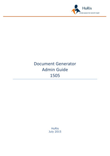
3. ESD ProtectionWhen servicing components in the ePlex instrument use appropriate ESD control mechanisms asappropriate such as static mats, wrist straps, and anti-static bags for printed circuit board assemblies.4. System Power4.1. Power Up ePlexConnect Power to the rear of the ePlex System.WARNING: Connect ePlex to line power using the supplied power cord which israted for 700W or more. Do not use a power cord rated for less than 700W.Turn the rear power switch ON ( ).Note: If the system was just powered down, wait 60 seconds before powering it back on.Press and release the front power switch to apply power to the Base.The ePlex instrument Software will automatically boot into Kiosk mode4.2. Power Down ePlexHalt processes as necessary to allow the system to save data.Press shutdown in Instrument SoftwareNote: If ePlex ISW is not responding you may continue to the next stepPress and release the front power button to power down the instrument.Flip the rear power switch to the OFF position (O).5. Base Fan Filter5.1. RemovalGrasp the fan filter tab and pull vertically to remove filter from holder.Figure 1: Base Fan Filter & Holder5.2. InstallationInsert the new fan filter back into the holder. Ensure that the filter media is facing towards thebase with the plastic tab on the outside.Refer to Figure 1 to verify that the filter has been installed properly.5 PageQWI4036 Rev. E
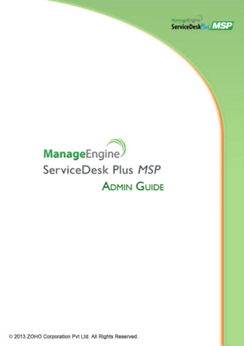
6. Tower Fan Filter6.1. RemovalGrasp the fan filter tab and pull vertically to remove filter from holder.Figure 2: Tower Fan Filter & Holder6.2. InstallationInsert a new fan filter back into the holder. Ensure that the filter media is facing towards the baseand the plastic tab is faced away from the base.Refer to Figure 2 to verify that the filter has been installed properly.7. Base Top Panel (Fascia)7.1. RemovalWARNING: Before removing any covers from the ePlex system, turn off the systemand disconnect the power cord from line power.Power down the Instrument per Section 4.2 and disconnect the power cord.Grasp the rear of the top fascia and gently pull up and away from the Base. Ball studs and clipshold the fascia in place and will release with a low pulling force.Move hands closer to the front ball clips and continue lifting to disengage the fascia.6 PageQWI4036 Rev. E
Figure 3 Base Top Panel7.2. InstallationAlign the top fascia mounting clips with the ball studs on the Base top and press downward on thefascia until the clips snap into place.8. Base Side Panel8.1. RemovalWARNING: Before removing any covers from the ePlex system, turn off the systemand disconnect the power cord from line power.Power down the Instrument and disconnect the power cord.Remove all Towers from Base if necessary.Disengage the thumbscrews from the rear of the panel. Refer to Figure 4.7 PageQWI4036 Rev. E
Figure 4: Base Side Panel RemovalFirmly slide the panel towards the rear of the Base to disengage the mounting studs.Lift the panel away from the Base.8.2. InstallationAlign the panel mounting studs with the mounting holes in the Base frame.Figure 5: Base Side Panel InstallationSlide the panel firmly toward the base front.Engage the thumbscrews on the rear of the panel.The side panel should be flush with top panel and front panel.Refer to Figure 6 to verify proper installation.8 PageQWI4036 Rev. E
Figure 6 Side Panel Alignment9. Solid State Drive9.1. RemovalEnsure a recent ePlex database backup file is availablePower down the ePlex and disconnect the power cord.Remove Towers from one side of Base if necessary, per Section 31.1.Remove a Base side panel per Section 8.Disconnect power cable and SATA cable from the drive.Push the release lever on the solid state drive housing to the side and remove the physical drive.Figure 7: Solid State DriveNote: Backup ePlex database prior to replacement of solid state drive to reinstate the system toprevious state. Also reimage solid state drive prior to replacement to remove any patient data fromthe drive9.2. InstallationPlace new solid-state drive into housing as shown in Figure 7.9 PageQWI4036 Rev. E
Reconnect power and SATA cables to the drive.The system network settings must be manually set in Windows OS after a new SSD is installed inorder for the base unit to properly communicate with towers and customer network.Connect an USB keyboard to the instrument and turn the instrument on.Load the latest OS image per the instructions in the ePlex Inspection and Installation Qualification(QWI4002)Set Network interface settings per the instructions in the ePlex Inspection and InstallationQualification (QWI4002)Reboot instrument and confirm towers and bays are communicating to base unit.Restore the ISW database. Refer to section 35.10. Memory SO-DIMM (small outline dual in-line memory module)10.1. RemovalPower down the Instrument and disconnect the power cord.Remove Towers from one side of Base if necessary, per Section 31.1.Remove a Base side panel per Section 8.Note the placement of the two sticks of RAM where one is placed on top of the other. If you need toreplace the RAM on the bottom, the stick on top must be removed first.Press down on the release tabs located on the sides to release the top DIMM and it willautomatically lift up to a 45 angle.Gently remove the DIMM from the memory slot at a 45 angle.Repeat steps 10.1.5 - 10.1.6 to remove the bottom DIMM if necessary.Figure 8: System Memory DIMMs10.2. InstallationInsert the new DIMM into the lower memory slot at a 45 angle and press down on the DIMM untilthe tab clicks and the DIMM is held flat and securely down.Repeat for the second DIMM.10 P a g eQWI4036 Rev. E
11. CMOS Battery11.1. RemovalPower down the Instrument and disconnect the power cord.Remove Towers from one side of Base if necessary, per Section 31.1.Remove a Base side panel per Section 8.Locate the CMOS battery (model: CR-2032) in the secondary battery socket located on thesystem motherboard as shown below.Remove the battery by pulling it up out of the socket.Figure 9 Motherboard Battery11.2. InstallationPlace new battery into the battery socket with the negative end (rough surface) facing forward(front of the base unit).Figure 10 CMOS Battery (CR-2032)Replacing the CMOS battery resets the system BIOS and the instrument touchscreen (both videooutput and touch input) will not be functional until the BIOS has been set to the correct settings.Connect a monitor to the VGA or DVI port on the motherboard inside the ePlex Base.11 P a g eQWI4036 Rev. E
Figure 11 Video Output PortsConnect an USB keyboard to the ePlex system.Power up the instrument and manually set BIOS as defined in the Systems BIOS Settings sectionof this document.Update System Date and Time in the Main tab of the BIOS Setup Utility if necessary.Confirm the touchscreen is functional, power down the instrument and disconnect the externalmonitor.12. Front USB Ports12.1. RemovalPower down the Instrument and disconnect the power cord.Remove Towers from right side of Base if necessary, per Section 31.1.Remove side panel from the right side of the Base per Section 8.Use a 3mm hex drive with driver to remove screw securing USB port bracket to the bottom panelof the base unit.Use a screw driver with a torque bit (T10) to remove the two screws securing the USB portbracket to the front panel of the base unit.Use a 3/32in hex drive with driver to remove the two screws securing the USB port to the bracket.Figure 12. Front USB Ports12 P a g eQWI4036 Rev. E
Trace the USB port cable to the connector at the other end and disconnect it from themotherboard. (Refer to Figure 17)12.2. InstallationPlug the USB port connector into the same USB port/header on the motherboard as the wire thatwas removed.Use a 3/32in hex drive with driver to attach USB port to bracket with two screws.Use a 3mm hex drive with driver to attach USB port bracket to the bottom of the base with asingle screw.Use a screw driver with a torque bit (T10) to attach USB port bracket to the front of the base withtwo screws.13. Rear USB Ports13.1. RemovalPower down the Instrument and disconnect the power cord.Remove Towers from right side of Base if necessary, per Section 31.1.Remove side panel from the right side of the Base per Section 8.Trace the USB port cable to the connector at the other end and disconnect it from themotherboard. (Refer to Figure 17)Use a 2mm hex driver with driver to remove the two screws securing the USB port to the backpanel of the base. (Refer to Figure 13.)Remove t
D34871-846 Plexus ePlex Wiring Diagram 2. Safety 2.1. Symbols used in this manual . Ensure a recent ePlex database backup file is available . order for the base unit to properly communicate with towers and customer network. Connect an U