Transcription
LS1Fuel PressureSending UnitTutorialAndy Reyna
LS1Fuel PressureSending UnitTutorialCopyright 1998-2006 EFILive Limited and Andy Reyna (TAQuickness).All rights reservedFirst publishedAug 12, 2006RevisedNeverDisclaimer:The author of this tutorial is in no way responsible for what you do with thisinformation. This tutorial has been written for informational purposes only. Inother words, use at your own risk.Credits:From the author: It is not my intent to take credit for work that is not mine.The content of this write up is largely derived from personal experience andinformation found on the Internet. If it looks like you originally wrote any partof this, you probably did, and I thank you for sharing that information on theInternet.Special thanks to: Beer99C5, CamTom12, DrX, and EFILive.EFILive is a registered trademark of EFILive Limited.AutoTap is a registered trademark of B&B Electronics Manufacturing Company.Acrobat Reader is a registered trademark of Adobe Systems Incorporated.Microsoft Windows is a registered trademark of Microsoft Corporation.All other trademarks belong to their respective owners.
EFILive LS1 Fuel Pressure Sending Unit TutorialEFILive V7 Scan and Tuning ToolContentsBefore you begin.2Install Sending Unit .3Leak Check .4General Wiring .5Pin-Outs.6FlashScan V1 Wiring .7EGR Wiring .8Configure Scan Tool .9Verify Results . 10support@efilive.com-1-www.efilive.com
EFILive LS1 Fuel Pressure Sending Unit TutorialEFILive V7 Scan and Tuning ToolBefore you beginThe test vehicles used while compiling this tutorial:2000 Pontiac Firebird:LS1 equipped, running EFILive Custom OS31999 Chevrolet Corvette:LS1 equipped, running OEM OS1. Please read the entire contents of this tutorial before performing any of thesteps.2. Upgrading to the latest release of the EFILive software will help ensure allfeatures are available and appear as documented.Upgrades may be downloaded, free of charge here:http://www.efilive.com/downloads/downloads 7.html3. This tutorial describes the steps necessary to install and configure Autometer’sfuel pressure sending unit (pn 2246) and wire harness (pn 5223), on an OEM(stock) fuel rail.4. A –4an to 1/8 NPT (female to female) fitting is required for the install. Thesefittings can be found in a number of speed shops and retail locations.5. A Schrader valve removal tools is required.6. A digital voltmeter is required.7. A fire extinguisher, safety glasses, and non-absorbent gloves are highlyrecommended.8. Do not smoke or work in areas that will ignite fuel.9. If you are not comfortable working with your vehicles fuel system, pleasehire a professional mechanic to install the fuel pressure sending unit.10. WORK SAFE! ! ! What’s the point of doing all this work if you kill orinjure yourself in the process!support@efilive.com-2-www.efilive.com
EFILive LS1 Fuel Pressure Sending Unit TutorialEFILive V7 Scan and Tuning ToolInstall Sending Unit1. Disconnect negative battery cable.2. Install –4an to 1/8 NPT fitting to sending unit (Teflon sealant, not tape, may beused).3. Relieve fuel system pressure.4. Remove Schrader valve from fuel rail.5. Install sending unit and fitting to fuel rail (Teflon sealant, not tape, may be used).support@efilive.com-3-www.efilive.com
EFILive LS1 Fuel Pressure Sending Unit TutorialEFILive V7 Scan and Tuning ToolLeak Check1. Place a thick pad of paper towels around the sending unit.2. Connect negative battery cable.3. Turn the key to the on position (DO NOT START ENGINE).4. Wait 5 seconds.5. Turn key off.6. Inspect paper towels for fuel.7. If any leaks are found, correct them before proceeding.8. Repeat this process 2 or 3 times. You do not want a fuel leak!support@efilive.com-4-www.efilive.com
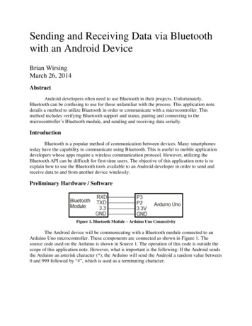
EFILive LS1 Fuel Pressure Sending Unit TutorialEFILive V7 Scan and Tuning ToolGeneral WiringAfter verifying there are no fuel system leaks, decide how to bring the fuel pressuresignal in. The simplest way is to wire directly into the FlashScan interface.Alternatively, the sending unit can be wired directly into the PCM via the EGR input.Vehicles that were not equipped with EGR from the factory can also utilize the EGRinput with some additional wiring (See PCM pin-outs below).The following information is common to all of the wiring installations:The sending unit runs on 5vdc. Applying 12vdc to the sending unit will fry the unitand likely void the warranty. The use of a 5vdc regulator (available from electronicparts stores) or one of the PCM’s 5vdc reference signals is highly recommended.The sending unit wire harness (5223) has five wires (2 red, 2 black, 1 purple), and twoends (1 square, 1 round). Only one end and three wires will be used.1. Connect the round end of the wire harness to the sending unit.2. Cut the square end of the wire harness off.If all steps were followed correctly, the wire harness will be connected to the sendingunit with approximately 20 feet of red, black, and purple wiring left.support@efilive.com-5-www.efilive.com
EFILive LS1 Fuel Pressure Sending Unit TutorialEFILive V7 Scan and Tuning ToolPin-OutsSending unit wire harness pin-out:Red 5vdcBlack GroundPurple 0-5vdc signal1998 LS1 PCM EGR Pin-Out:Red Connector:Pin 62, Black, EGR Pintle Position GroundBlue Connector:Pin 9, Brown, EGR Pintle Position Sensor SignalPin 65, Grey, 5V Reference1999 LS1 PCM EGR Pin-Out:Blue Connector:Pin 41, Black, EGR Pintle Position GroundPin 47, Grey, EGR Pintle Position Sensor 5V ReferencePin 55, Brown, EGR Pintle Position Sensor Signalsupport@efilive.com-6-www.efilive.com
EFILive LS1 Fuel Pressure Sending Unit TutorialEFILive V7 Scan and Tuning ToolFlashScan V1 Wiring1. Route the purple wire from the sending unit wire harness to the FlashScaninterface.2. Connect the sending unit purple wire to terminal C or E on the FlashScaninterface (see pin-out below).3. Connect the sending unit red wire to 5vdc (either regulator or PCM EGRreference voltage).4. Connect the sending unit black wire to chassis ground or PCM EGR ground.support@efilive.com-7-www.efilive.com
EFILive LS1 Fuel Pressure Sending Unit TutorialEFILive V7 Scan and Tuning ToolEGR Wiring(All LS1 PCM’s 1997 )1. Turn the key to the on position – do not start engine.2. Locate the EGR wire harness.3. The EGR harness has two grey wires. Use a voltmeter to identify the grey wirewith 5vdc. The other grey wire is ground for the EGR solenoid and will likelymeasure 0 volts.4. Turn the key off.5. Connect the sending unit red wire to the EGR 5vdc grey wire.6. Connect the sending unit black wire to the EGR black wire.7. Connect the sending unit purple wire to the EGR brown wire.8. Open the tune tool and verify {B1301} is set to enable. Re-flash if necessary.Vehicles with out EGR from the factory:Most Corvettes, 2001 vehicles were not equipped with the EGR system; however, thePCM still has provisions for the EGR. By enabling {B1301} and wiring the sending unitdirectly to the PCM (see PCM pin-outs on previous page), fuel pressure may bemonitored via the EGR PID’s in the scan tool.support@efilive.com-8-www.efilive.com
EFILive LS1 Fuel Pressure Sending Unit TutorialEFILive V7 Scan and Tuning ToolConfigure Scan ToolAdditional information on creating custom PID’s can be found in the Scan Tool help.1. Locate the file “calc pids.txt”, default directory: My Documents\EFILive\V7\UserConfiguration, and open with notepad.exe.2. The following information in the box below needs to be added to calc pids.txt:# # File details# -----------# This section defines various details about the file format.*FILE#Parameter ValueDescription#---------- ---------------- VERSION7.1.1File versionDECSEP.Decimal separator used in this file# # Units# #-------- ---------- -------- SIImperialPSI"Pounds Per Square Inch"# # Add slot definitions here# -------------------------------#UnitsLowHighFmt Expression#------------ ------------- ------------- ---- 100.00.2"({xxx.xxx}*25)-12.5"# *PRN - Parameter Reference Numbers# -------------------------------#CodePRN SLOTUnitsSystemDescription#------------- ---- ------------ ------------ ------------ --------------------CALC.FPF001 CLC-00-001PSIFuel"Fuel Pressure"FlashScan connections xxx.xxx EXT.AD1 or EXT.AD2EGR connections xxx.xxx GM.EGRSsupport@efilive.com-9-www.efilive.com
EFILive LS1 Fuel Pressure Sending Unit TutorialEFILive V7 Scan and Tuning ToolVerify ResultsBefore verifying results, make one last visual inspection of the sending unit install.Verify there are no leaks and all electrical connections are solid.1. Open the scan tool.2. Select the PID tab (F8)3. For FlashScan installations, select the following PID’s EXT.AD1or EXT.AD2 CALC.FP4. For EGR Installations, select the following PID’s GM.EGRS CALC.FP5. Start the engine6. Connect to the vehicle (Ctrl F3)7. Start Logging (F3)8. Select the Data Tab (F9)Stock fuel rail pressure is 58 PSI. Fuel rail pressure may vary with fuel systemupgrades or degrading fuel system components.support@efilive.com- 10 -www.efilive.com
EFILive LS1 Fuel Pressure Sending Unit Tutorial EFILive V7 Scan and Tuning Tool support@efilive.com - 4 - www.efilive.com Leak Check 1. P