Transcription
PDHonline Course M312 (4 PDH)Fire Dynamics Series: Estimating FireFlame Height and Radiant Heat FluxFrom FireInstructor: Lawrence J. Marchetti, PE, CFPS2012PDH Online PDH Center5272 Meadow Estates DriveFairfax, VA 22030-6658Phone & Fax: 703-988-0088www.PDHonline.orgwww.PDHcenter.comAn Approved Continuing Education Provider
CHAPTER 5. ESTIMATING RADIANT HEAT FLUXFROM FIRE TO A TARGET FUEL5.1ObjectivesThis chapter has the following objectives: Introduce the three modes of heat transfer. Explain how to calculate the heat flux from a flame to a target outside the flame. Discuss point source radiation models and solid flame radiation models. Identify the difference between solid flame radiation models at ground level and solid flameradiation models above ground level with and without wind. Define relevant terms, including, conduction, convection, radiation, heat flux, emissive power,and configuration factor.5.2IntroductionFire normally grows and spreads by direct burning, which results from impingement of the flameon combustible materials, or from heat transfer to other combustibles by means of conduction,convection, or radiation. All three of these modes of heat transfer may be significant, dependingon the specifics of a given fire scenario. Conduction is particularly important in allowing heat topass through a solid barrier (e.g., fire wall) to ignite material on the other side. Nevertheless, mostof the heat transfer in fires typically occurs by means of convection and/or radiation. In fact, it isestimated that in most fires, approximate 70-percent of the heat emanates by convection (heattransfer through a moving gas or liquid). Consider, for example, a scenario in which a fire produceshot gas which is less dense than the surrounding air. This hot gas then rises, carrying heat. Thehot products of combustion rising from a fire typically have a temperature in the range of800–1,200 C (1,472–2,192 F) and a density that is one-quarter that of ambient air. In the thirdmode of heat transfer, known as radiation, radiated heat is transferred directly to nearby objects.One type of radiation, known as thermal radiation, is the significant mode of heat transfer forsituations in which a target is located laterally to the exposure fire source. This would be the case,for example, for a floor-based fire adjacent to an electrical cabinet or a vertical cable tray in a largecompartment. Thermal radiation is electromagnetic energy occurring in wavelengths from 2 to16 mm (infrared). It is the net result of radiation emitted by the radiating substances such as water(H 2 O), carbon dioxide (CO 2 ), and soot in the flame.Chapter 2 discussed various methods of predicting the temperature of the hot gas layer and theheight of the smoke layer in a room fire with natural or forced ventilation. However, those methodsare not applicable when analyzing a fire scenario in a very large open space or compartment.In large spaces, such as the reactor building in a boiling water reactor (BWR) or an open space ina turbine building, the volume of the space is too large for a uniform hot gas layer to accumulate.For such scenarios, fire protection engineers must analyze other forms of heat transfer, such asradiation. A floor-mounted electrical cabinet is an example of a ground-level target. A typical targetabove ground level is an overhead cable tray.5-1
5.3Critical Heat Flux to a TargetRadiation from a flame, or any hot gas, is driven by its temperature and emissivity. The emissivityis a measure of how well the hot gas emits thermal radiation (emissivity is defined as the ratio ofradiant energy emitted by a surface to that emitted by a black body of the same temperature).Emmisivity is reported as a value between 0 and 1, with 1 being a perfect radiator. The radiationthat an observer feels is affected by the flame temperature and size (height) of the flame.The incident heat flux (the rate of heat transfer per unit area that is normal to the direction of heatflow. It is a total of heat transmitted by radiation, conduction, and convection) required to raise thesurface of a target to a critical temperature is termed the critical heat flux. Measured critical heatflux levels for representative cable samples typically range from 15 to 25 kW/m 2 (1.32 to 2.2 Btu/ft 2sec). For screening purposes, it is appropriate to use value of 10 kW/m 2 (0.88 Btu/ft 2-sec) for IEEE383 qualified cable and 5 kW/m 2 (0.44 Btu/ft2 -sec) for IEEE-383 unqualified cable. These valuesare consistent with selected damage temperatures for both types of cables based on the ElectricalPower Research Institute (EPRI), “Fire-Induced Vulnerability Evaluation (FIVE),” methodology.Researchers have developed numerous methods to calculate the heat flux from a flame to a targetlocated outside the flame. Flames have been represented by cylinders, cones, planes, and pointsources in an attempt to evaluate the effective configuration factors 1 between the flame and thetarget. Available predictive methods range from those that are very simple to others that are verycomplex and involve correlations, detailed solutions to the equations of radiative heat transfer, andcomputational fluid mechanics. Routine FHAs are most often performed using correlationally basedapproaches, because of the limited goals of the analyses and the limited resources available forroutine evaluation. As a result of their widespread use, a great deal of effort has gone into thedevelopment of these methods. Burning rates, flame heights, and radiative heat fluxes are routinelypredicted using these approaches.Fire involving flammable and combustible liquids typically have higher heat release rates (for thesame area of fuel involved) than ordinary combustibles fires. The flame from a liquid fire is typicallytaller, making it a better radiator. Hydrocarbon liquid fires are also quite luminous because of thequantity of soot in the flames. Sooty fires are better emitters of thermal radiation. Thus, anobserver approaching a flammable/combustible liquid fire feels more heat than an observerapproaching an ordinary combustibles fire of comparable size.The methods presented in this chapter are drawn from the SFPE Handbook of Fire ProtectionEngineering, 3 rd Edition, 2002, which examines the accuracy of these methods by comparisonswith available experimental data (these methods also presented in the SFPE Engineering Guide,“Assessing Flame Radiation to External Targets from Pool Fires,” June 1999).1The configuration factor is a purely geometric quantity, which gives the fraction of the radiationleaving one surface that strikes another surface directly.5-2
5.3.1Point Source Radiation ModelA point source estimate of radiant flux is conceptually the simplest representation configurationalmodel of a radiant source used in calculating the heat flux from a flame to target located outsidethe flame. To predict the thermal radiation field of flames, it is customary to model the flame basedon the point source located at the center of a flame 2. The point source model provides a simplerelationship that varies as the inverse square of the distance, R. For an actual point source ofradiation or a spherical source of radiation, the distance R is simply the distance from the point orfrom the center of the sphere to the target.The thermal radiation hazard from a fire depends on a number of parameters, including thecomposition of the fuel, the size and the shape of the fire, its duration, proximity to the object at risk,and thermal characteristics of the object exposed to the fire. The point source method may be usedfor either fixed or transient combustibles. They may involve an electrical cabinet, pump, liquid spill,or intervening combustible at some elevation above the floor. For example, the top of a switchgearor motor control center (MCC) cabinet is a potential location for the point source of a postulated firein this type of equipment. By contrast, the point source of a transient combustible liquid spill orpump fire is at the floor.The point source model assumes that radiant energy is released at a point located at the center ofthe fire. The radiant heat flux at any distance from the source fire is inversely related to thehorizontal separation distance (R), by the following equation (Drysdale, 1998):(5-1)Where: radiant heat flux (kW/m 2 ) heat release rate of the fire (kW)R radial distance from the center of the flame to the edge of the target (m)c r fraction of total energy radiatedIn general, c r depends on the fuel, flame size, and flame configuration, and can vary fromapproximately 0.15 for low-sooting fuels (e.g., alcohol) to 0.60 for high sooting fuels (e.g.,hydrocarbons). For large fires (several meters in diameter), cold soot enveloping the luminousflames can reduce c r considerably. See Figure 5-1 for a graphic representation of the relevantnomenclature.2More realistic radiator shapes give rise to very complex configuration factor equations.5-3
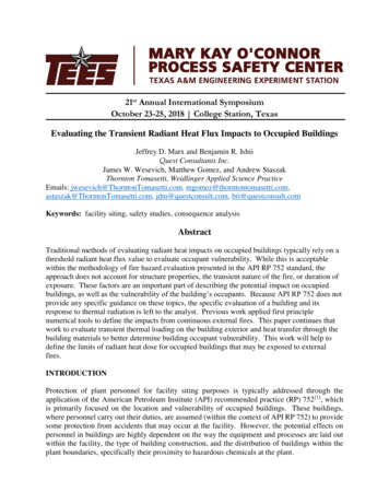
Figure 5-1 Radiant Heat Flux from a Pool Fireto a Floor-Based Target Fuel (Point Source Model)The HRR of a fire can be determined by laboratory or field testing. In the absence of experimentaldata, the maximum HRR for the fire, is given by the following equation (Babrauskas, 1995):(5-2)Where: heat release rate of the fire (kW) burning or mass loss rate per unit area per unit time (kg/m 2 -sec)DH c,eff effective heat of combustion (kJ/kg)A f horizontal burning area of the fuel (m 2 )k empirical constant (m -1 )D diameter of burning area (m)For non-circular pools, the effective diameter is defined as the diameter of a circular pool with anarea equal to the actual pool area, given by the following equation:(5-3)Where:A f surface area of the non-circular pool (m 2 )D diameter of the fire (m)5-4
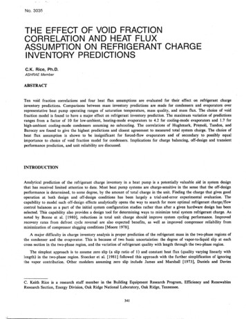
5.3.2Solid Flame Radiation Model with Target At and Above Ground LevelThe solid flame spreadsheet associated with this chapter provides a detailed method for assessingthe impact of radiation from pool fires to potential targets using configuration factor algebra. Thismethod covers a range of detailed calculations, some of which are most appropriate for first orderinitial hazard assessments, while others are capable of more accurate predictions.The solid flame model assumes that, (1) the fire can be represented by a solid body of a simplegeometrical shape, (2) thermal radiation is emitted from its surface, and, (3) non-visible gases donot emit much radiation. (See Figures 5-2 and 5-3 for general nomenclature.) To ensure that thefire volume is not neglected, the model must account for the volume because a portion of the firemay be obscured as seen from the target. The intensity of thermal radiation from the pool fire toan element outside the flame envelope for no-wind conditions and for windblown flames is givenby the following equation (Beyler, 2002):(5-4)Where: incident radiative heat flux (kW/m 2 )E average emissive power at flame surface (kW/m 2 )F 16 2 configuration factorFigure 5-2 Solid Flame Radiation Model with No Windand Target at Ground Level5-5
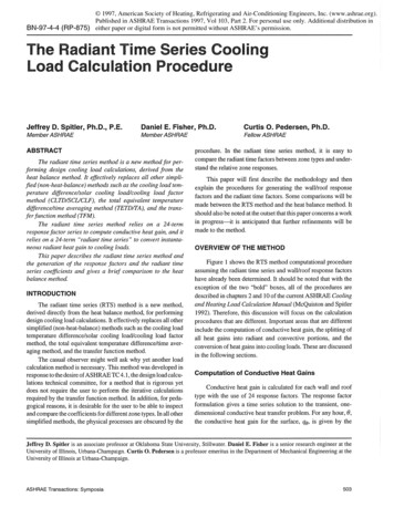
Figure 5-3 Solid Flame Radiation Model with No Windand Target Above Ground5.3.2.1Em issive PowerEmissive power is the total radiative power leaving the surface of the fire per unit area per unit time.Emissive power can be calculated using of Stefan’s law, which gives the radiation of a black bodyin relation to its temperature. Because a fire is not a perfect black body (black body is defined asa perfect radiator; a surface with an emissivity of unity and, therefore, a reflectivity of zero),the emissive power is a fraction (e) of the black body radiation (Beyler, 2002):(5-5)Where:E flame emissive power (kW/m 2 )e flame emissivitys Stefan-Boltzmann constant 5.67 x 10 -11 (kW/m 2 -K 4 )T temperature of the fire (K)5-6
The use of the Stefan-Boltzmann constant to calculate radiation heat transfer requires knowledgeof the temperature and emissivity of the fire; however, turbulent mixing causes the fire temperatureto vary. Consequently, Shokri and Beyler (1989) correlated experimental data of flame radiationto external targets in terms of an average emissive power of the flame. For that correlation, theflame is assumed to be a cylindrical, black body, homogeneous radiator with an average emissivepower. Thus, effective power of the pool fire in terms of effective diameter is given by:(5-6)Where:E flame emissive power (kW/m 2 )D diameter of pool fire (m)This represents the average emissive power over the whole of the flame and is significantly lessthan the emissive power that can be attained locally. The emissive power is further reduced withincreasing pool diameter as a result of the increasing prominence of black smoke outside the flame,which obscures the radiation from the luminous flame.For non-circular pools, the effective diameter is defined as the diameter of a circular pool with anarea equal to the actual pool area given by Equation 5-3.5.3.2.2Configuration Factor F 1 6 2 under Wind-Free ConditionsThe configuration factor 3 is a purely geometric quantity, which provides the fraction of the radiationleaving one surface that strikes another surface directly. In other words the configuration factorgives the fraction of hemispherical surface area seen by one differential element when looking atanother differential element on the hemisphere.The configuration factor is a function of target location, flame size (height), and fire diameter, andis a value between 0 and 1. When the target is very close to the flame, the configuration factorapproaches 1, since everything viewed by the target is the flame. The flame is idealized with adiameter equal to the pool diameter, D, and a height equal to the flame height, H f. If the pool hasa length-to-width ratio near 1, an equivalent area circular source can be used in determining theflame length, H f, for non-circular pools. (See Figure 5-4 and 5-5 for general definitions applicableto the cylindrical flame model under wind-free conditions.)3The configuration factor is also commonly referred to as the “view factor”.5-7
Figure 5-4 Cylindrical Flame Shape Configuration Factor Geometryfor Vertical and Horizontal Targets at Ground Level with No WindFigure 5-5 Cylindrical Flame Shape Configuration Factor Geometryfor Vertical and Horizontal Targets Above Ground with No Wind5-8
Flame height of the pool fire is then determined using the following correlation (Heskestad, 1995):(5-8)Where:H f flame height (m) heat release rate of the fire (kW)D diameter of the burning area (m)The HRR of the fire can be determined by laboratory or field testing.experimental data, the maximum HRR for the fireIn the absence of, is given by Equation 5-2.The radiation exchange factor between a fire and an element outside the fire depends on the shapeof the flame, the relative distance between the fire and the receiving element, and the relativeorientation of the element. The turbulent diffusion flame can be approximated by a cylinder. Underwind-free conditions, the cylinder is vertical (Figure 5-4). If the target is either at ground level or atthe flame height, a single cylinder can represent the flame. However, if the target is above theground, two cylinders should be used to represent the flame.For horizontal and vertical target orientations at ground level with no-wind conditions, given thediameter and height of the flame, the configuration (or view factor) F 16 2 under wind-free conditionsis determined using the following equations related to cylindrical radiation sources (Beyler, 2002):(5-9)(5-10)Where:And:L the distance between the center of the cylinder (flame) to the target (m)H f the height of the cylinder (flame) (m)D the cylinder (flame) diameter (m)5-9
The maximum configuration factor (or view factor) at a point is given by the vectorial sum of thehorizontal and vertical configuration factors:(5-11)As previously stated, for targets above the ground, two cylinders should be used to represent theflame. In such instances, one cylinder represents the flame below the height of the target, whilethe other represents the flame above the height of the target (See Figure 5-5). Thus, the followingexpressions are used to estimate the configuration factor (or view factor) under wind-free conditionsfor targets above ground level:(5-12)Where:(5-13)Where:And:L the distance between the center of the cylinder (flame) to the target (m)H f the height of the cylinder (flame) (m)D the cylinder (flame) diameter (m)The total configuration factor or (view factor) at a point is given by the sum of two configurationfactor as follows:(5-14)5-10
5.3.2.3Configuration Factor F 1 6 2 in Presence of WindAs discussed in pervious section, in the solid flame radiation model the turbulent flame isapproximated by a cylinder. Under wind-free conditions, the cylinder is vertical, in the presence ofwind, the flame may not remain vertical and thermal radiation to the surrounding objects will changein the presence of a significant wind. The flame actually follows a curved path and makes an angleof tilt or an angle of deflection approximate to its curved path. Figures 5-6 and 5-7 describe theflame configuration in presence of wind velocity (u w) for target at and above ground level.Figure 5-6 Solid Flame Radiation Model in Presence of Windand Target Above Ground LevelFigure 5-7 Solid Flame Radiation Model in Presence of Windand Target at Ground Level5-11
For horizontal and vertical target orientations at ground level in presence of wind, the expressionfor estimating the configuration factors is expressed by the following equations (Beyler, 2002):(5-15)(5-16)Where:And:H f the height of the tilted cylinder (flame) (m)r the cylinder (flame) radius (m)R distance from center of the pool fire to edge of the target (m)q flame title or angle of deflection (radians)The maximum configuration factor for a target at ground level in the presence of wind at a pointis given by the vectorial sum of the horizontal and vertical configuration factors:(5-17)5-12
For targets above the ground in presence of wind, two cylinders must be used to represent theflame. In such instances, one cylinder represents the flame below the height of the target, whilethe other represents the flame above the height of the target. The following expressions are usedto estimate the configuration or view factor in presence of wind for targets above ground level:(5-18)(5-19)Where:And:H 1 H f1 vertical distance of target from ground level (m)H f the height of the tilted cylinder (flame) (m)r the cylinder (flame) radius (m)R distance from center of the pool fire to edge of the target (m)q flame title or angle of deflection (radians)5-13
The total configuration or view factor at a point is given by the sum of two configuration factors,as follows:(5-20)In presence of wind, the expression for estimating flame height is expressed by the followingcorrelation, based on the experimental data (Thomas, 1962):(5-21)Where:D diameter of pool fire (m) mass burning rate of fuel (kg/m 2-sec)r a ambient air density (kg/m 3 )g gravitational acceleration (m/sec 2)u* nondimensional wind velocityThe nondimensional wind velocity is given by:(5-22)Where:u* nondimensional wind velocityu w wind speed or wind velocity (m/sec)g gravitational acceleration (m/sec 2) mass burning rate of fuel (kg/m 2 -sec)D diameter of pool fire (m)r density of ambient air (kg/m 3)The correlation relating to angle of tilt or angle of deflection (q), of the flame from the verticalare expressed by the following equations based on the American Gas Association (AGA) data:(5-23)Where:q angle of tilt or angle of deflection (radians)u* nondimensional wind velocity5-14
5.4Method of Estimating Thermal Radiation from Hydrocarbon FireballFor industrial processes, many substances that are gases at ambient conditions are stored inconta
radiant energy emitted by a surface to that emitted by a black body of the same temperature). Emmisivity is reported as a va lue between 0 and 1, with 1 being a perfect radiator. The radiation that an observer feels is affected