Transcription
School of Mechanical & Manufacturing (SMAE)Design & Fabrication Project (EC1166)Automated Guided Vehicle (AGV)Prepared For:MR. CHOY FOOK SENGPrepared By:KYAW SOE HEIN0856566KYI HLA WIN0856777GARRY HAN0847007AYE MYAT MON0856818CLASS : DMA/FT/2B/041ST FEB, 2010
EC1166 (DFBP)LC0503 (RWP)Table of Contents12PagesOverview3Introduction41.1 Objectives41.2 Scope of Work41.3 Design Specifications41.4 Functions of AGV51.5 Application of AGV in Industry5Design Description72.1 Mechanical Design72.1.1Design of AGV82.1.1.1 Base Plate & Roof82.1.1.2 Wheels & Sensor Board82.1.1.3 Fork Lift82.1.2Software Application102.1.2.1 AutoCAD for AGV102.1.2.2 Solid Modelling 3D Design102.1.2.3 UCS System112.1.2.4 Usage of Commands112.1.2.5 2D Detailed Drawings112.1.2.6 First & Third Angle Projection122.1.2.7 Assembly Drawing122.1.3Fabrication Process132.1.3.1 Machines132.1.3.2 General Mechanical Tools132.1.3.3 Lathe Machine142.1.3.4 Milling Machine142.1.3.5 Drilling Machine142.1.3.6 Shearing Machine142.2 Electronics Design2.2.115Sensor Board152.2.1.1 Structure152.2.1.2 Components162.2.1.3 Sensor Board Silkscreen & Artwork162.2.1.4 Surface Mounting171
EC1166 (DFBP)LC0503 (RWP)2.2.1.5 Schematic Diagram182.2.1.6 How It Works192.2.1.7 Finalized Board192.2.2202.2.2.1 Components and Description222.2.2.2 How It Works232.2.2.3 Hardware Testing242.2.2.4 Manual Test242.2.33Motor BoardSoftware Description262.2.3.1 Program262.2.3.2 Flow Chart32Testing & Troubleshooting353.1 Testing & Troubleshooting of Mechanical Hardware353.2 Procedure to Check the Requirement of AGV353.2.1Dimension353.2.2Forklift Function353.2.3The Roof Accessibility353.2.4Checking Alignment353.3 Problems Encountered in Assembling363.3.1Dimension in Forklift Column363.3.2Drilling Holes363.3.3Tapping Holes363.3.4Troubleshooting363.4 Testing & Troubleshooting of Electronics373.4.1Microcontroller Board373.4.2Sensor Board393.4.3Motor Board393.4.4Testing & Troubleshooting of Stepper Motor403.4.5Testing & Troubleshooting of DC Motor404Conclusion415Discussions & RecommendationsAppendicesAppendix I – Assembly & Detailed Drawings of the AGVAppendix II – Fabrication Procedure WorksheetsAppendix III – Standard Parts Catalogue422
EC1166 (DFBP)LC0503 (RWP)OverviewIn the second semester of Year 2, all Diploma in Mechatronics (DMA) students have toundergo a Design and Fabrication Project, which requires them to build an AutomaticGuided Vehicle (AGV). As part of the criteria, the classes are divided into groups of fourstudents, who collaborate and fuse talents together to create an AGV which has to beoutstanding in both design and mechanism.An AGV is a four-wheeled vehicle with an Infra-Red sensor attached to the underneath ofthe front part of it that detects a strip of aluminium foil guiding its way. The AGV will readand follow the path as it is programmed.3
EC1166 (DFBP)LC0503 (RWP)REPORT ON THE AUTOMATED GUIDED VEHICLE (AGV) PROJECT1.0 INTRODUCTION1.1ObjectivesThe objective of building this AGV is to equip students with necessary handson skills on designing, fabricating and assembling of the mechanical structureand electronic parts of an automated vehicle. The critical part is tounderstand the concepts of design, drawings, process planning, machiningand assembling, which increases in complexity as the mechanical andelectrical parts integrate to work together. Students are expected totroubleshoot problems that arise from both mechanical & electronics aspectsand be able to overcome these obstacles while completing the project ontime.1.2Scope of WorkThis report will mainly focus on areas involved in creating the AGV, whilereflecting the efforts invested by the team. The areas include DesignDescription, Testing & Troubleshooting, and Discussion & Recommendation.The section on Design Description will then be sub-divided into two key areaslike software description and mechanical assembling description. The sectionon Testing & Troubleshooting will emphasize on dimensional and tolerancecontrol and machining errors. Moreover, the section on testing PCB (PrintedCircuit Board) and troubleshooting of electronics components will be coveredin this report. Finally, this report will detail recommendations that will beprovided for better and safer applications.1.3Design SpecificationsA standard AGV measures 25cm in length, 20cm in width and 25cm in height.It has four wheels for its movement, two large motor-driven wheels and twosmaller direction-adjustable wheels which perform a task of height balancing.A crucial part is the front fork-lift, which functions very similarly to thecounterparts of the industry. A sensor board for track detection is attachedto the front lower part. The AGV consists of two main circuit boards, whichfacilitate for easy investigation and troubleshooting.4
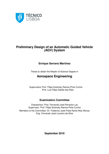
EC1166 (DFBP)LC0503 (RWP)1.4Functions of AGVA completed AGV performs two fundamental functions. First, it should detectand move along a designated path.Second is the forklift which is designed to carry small sample weights, thefork-lift should move up and down by at least 10cm, and is controlled by aMicrocontroller board, which is tuned with a language called AssemblyLanguage. The Microcontroller board is linked with a geared motor, thatturns a screw thread.1.5 Application of AGV in IndustryAn AGV does pre-determined standard procedures at a calculated rate. Itsoverall advantage is increased efficiency. AGVs are most appropriately usedin Industries which require repetitive work. Another advantage is the lack offatigue frequency of machines. Humans need to rest after carrying heavyobjects, and thus wasting time. By using AGVs, the industry could improvequality of its service, mainly transporting components, in the Industry bydoing steady, reliable jobs. The most common application of AGV in Industryis in the dockyards (For example, Keppel Shipyard), warehouses and factories.As shown below, Fig 1.1 and 1.2 are two pictures depicting AGVs forIndustrial use.5
EC1166 (DFBP)LC0503 (RWP)Fig 1.1 - A Fully-Functional AGV for Industrial use(Source: Google Image Finder - images.google.com)Fig 1.2 - An AGV carrying bulky items in a factory(Source: Google Image Finder – images.google.com)6
EC1166 (DFBP)LC0503 (RWP)2.0 Design Description2.1 Mechanical DesignThis section will discuss on Mechanical parts of AGV in the aspects of Design & process toobtain Hardware parts.Parts of the AGV can be broken down into two main groups, namely Chassis (Body of thecar) & Fork Lift.The entire idea of utilizing the AGV in application is to transport objects by means ofautomated vehicle. In addition, lifting the objects up and down is done by fork lift which isinstalled onto the main body of the car. Therefore, different parts of each group aremachined to fabricate accordingly to be able to fit into one as an AGV.GroupChassisName of the parts1. Base Plate2. Brackets3. Wheels4. T-mount(Supporting brackets forwheels)5. Motor Supporting Brackets6. PCB supportFork Lift1.2.3.4.5.6.7.Fork ColumnFork Lift TopFork Lift Guide BlockFork BaseFork WedgeGuide RodLead ScrewTable 1.1 List of the different parts of AGVThe general design of the AGV is fairly similar to locomotive robot which has locomotors(Wheels) and fork Lift at the front end to pick up things and transport them.7
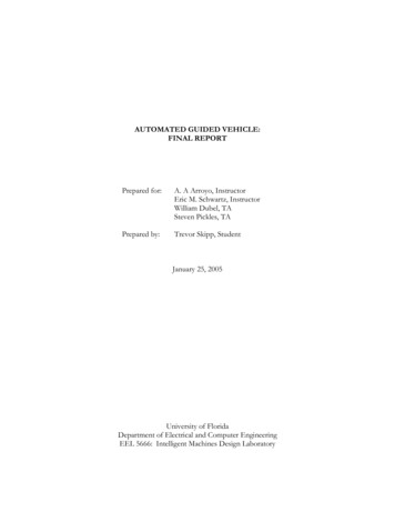
EC1166 (DFBP)LC0503 (RWP)2.1.1 Design of AGV2.1.1.1 Base Plate & RoofIt has a broad base to stabilize itself while moving. In technical terms, the base measures 25cm in length and 20 cm in width. The height of the fork lift column where the fork base isattached is 25 cm. Thus, it makes the centre of gravity of the AGV (The point at whichweight of the AGV, in this case, concentrated) lower, and hence it provides higher stability.Furthermore, the electronic systems are integrated on the AGV by mounting PCB on thebase plate. These electrical boards are covered by a rigid roof which in turn can protectcircuit boards from external disturbance. This is particularly the best idea of the designwhich will provide robustness and safe condition for electronic components.2.1.1.2 Wheels & Sensor BoardThe castor wheels (Rubber wheels) are used to turn left or right depending on themovement of the rear wheels which are driven by stepper motors and they lead the waydirected by a sensor board located in the front. Those large diameter wheels are designedfor fast movement.The sensor board is attached to lower surface of the base plate right below the fork liftcolumn.2.1.1.3 Fork LiftParticularly, fork lift is another strong point of the design. Normally fork wedges, the twolaterally extended appendices, are short and small making it difficult to lift heavy and largesize loads. However, in this case, relatively long and strong fork wedges are installed forbetter efficiency. The wedges are attached to the wide fork lift base which in turn givesstronger and more stable applied force while lifting the loads. The fork lift base, in turn, isattached to the guide block which is placed between the fork lift columns. The guide block isresponsible for vertical movement of the fork.The movement of the fork is being driven by motor which is mounted on the base plate atthe front end. At the tip of the power transmitting rod from the motor is a gear with teethwhich rotates horizontally. On the other hand, the screw lead which moves the guide blockcreates the perfect gear system with transmitting rod. The screw lead is in vertical positionand transmitting rod from DC motor is in horizontal position hence touching the tips ofthem at the point making 90 Deg angle and there is teeth fitting in each other.8
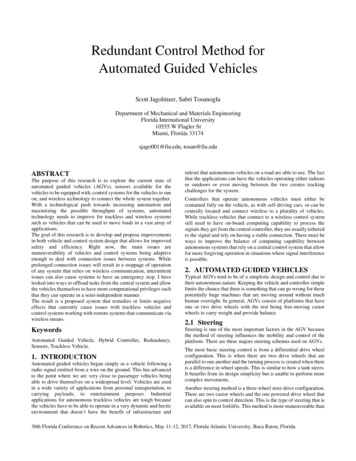
EC1166 (DFBP)LC0503 (RWP)In other words, when the power transmitting rod is rotating, the screw lead will be rotatingas well because they are in same gear system. Therefore the guide block along with the forkwill be moving upwards or downwards depending on the direction of rotation of the screwlead. The guide block is supported by two brass rod for its stabilized vertical movement.Fig 2.1 - A 3D generated image of our AGV, with the most fundamental features visible9
EC1166 (DFBP)LC0503 (RWP)2.1.2 Software ApplicationBefore fabricating the actual hardware (mechanical portion) of the AGV, the use ofsoftware, AutoCAD software is crucial to be fully accomplished. First of all, the AGV design isdeveloped from the rough sketch. After developing rough sketch, the 3D drawing of AGVdesign is drawn so that it is possible to visualize and judge dimension of the entire car. Aseach individual part of the AGV car is to be machined precisely, it is drawn in 2D detaildrawing assisting in actual fabricating process as well. These assessments acquire the aid ofparticular software, AutoCAD, one of the world leading cad software to interpret 2D, 3D,which provides ultimate in flexibility, powerful features, design and speedy documentationsoftware.2.1.2.1 AutoCAD for AGVTo start off with the assessment of fabricating the AGV car, students are to use AutoCADsoftware. The main purpose is to teach the students to utilize the knowledge attained fromprevious module taken, which is, computer-aided drafting module (AutoCAD), in year onestage B as well as to familiarize or practice the use of AutoCAD synchronizing with industrialmanufacturing process. Students are provided with relevant templates featuring respectivetolerances, dimension style, etc as well as systematic guideline of labeling by whom whichpart is drawn or checked. Each group performance is guided by supervisor for continuousassessment grading the progress of every week. The procedure for drawing process includessolid modeling 3D, 2D detailed drawings for machining individual parts and assemblydrawing according to module map (assessment plan).2.1.2.2 Solid Modelling 3D DesignUpon the confirmation of design sketching, the engineering drawing for fabricating purposeis completed by using AutoCAD 3D style. Initially, the dimension of standard parts providedby workshops such as miter gears, motors, castor wheels, bearings and screws are closelyobserved and the general idea of overall dimension from previous cars are measured ornoted as reference for upgrading the design. What is more, the additional parts of newinnovative design are considerably decided for dimension after the group discussion. Whiledeciding the dimension of the car, the drafter should reckon to make use of the workshop'smaterials, standard material size available to minimize machining several parts for savingtime and cost. As all the dimensions are confirmed, solid model is created using 3Dconcepts. 3D design can represent the entire volume of the object regardless of the shapeof object.10
EC1166 (DFBP)LC0503 (RWP)2.1.2.3 UCS SystemThe entire AGV is drawn by using UCS ( user coordinate system), which facilitates the userre-orientating the X-Y plane from 2D profiles to 3D solids so that the different parts of thecar are drawn conveniently over different views, different orientation making it easier todraw out the 3D complete design. Each part is drawn from respective view followed bycompiling them together.2.1.2.4 Usage of commandsIt is compulsory to know 3D commands to work out the drawing as it is relatively difficult todraw some critical parts such as gears and hinges( attached to the roof of the design).Therange of commands need to be revised properly to accomplish the model drawing. Thesupervisor checked on the proper dimension and appropriate positioning for approval.2.1.2.5 2D Detailed DrawingsIn order to fabricate each component, 2D detailed drawings for individual parts are drawnusing orthographic projection principle, projecting a number of separate two dimensionalinter-related views which are mutually at right angles to each other.Fig 2.2 Third Angle projection(Source: loads/2009/07/third angle projecting.png)2.1.2.6 First and Third Angle Projection11
EC1166 (DFBP)LC0503 (RWP)In third angle projection, object is positioned in third-angle quadrant between two principalplanes. The view of object by drawing parallel lines from the object to the vertical plane isfront view or elevation. The view similarly projected to the horizontal plane is called a topview or plan. The view projected on to the auxiliary vertical plane is called and end view. ForAGV, third angle projection concept is applied to draw out all the 2D drawings. Figure shownbelow is the planning of third angle projection.Fig2.3 - Comparison of the positioning plan of first to third angle projection(Source: mages/dt g dmi tp9.gif) [accessed on10/01/10]2.1.2.7 Assembly DrawingFinally assembly drawing for the whole car is produced. The guideline to directly transformfrom 3D isometric drawing to assembly drawing is provided in blackboard. Assemblydrawing shows how the parts are fitted to make a complete unit and provide a visual imageof how the finished product should look like when the parts are assembled. The individualpart is indicated by a balloon with an arrowhead on the drawing of that particular part. Thepart list with detail description, material used and quantity of all the parts are included inthe drawing.(refers to Appendix I).12
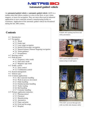
EC1166 (DFBP)LC0503 (RWP)2.1.3 Fabrication ProcessBefore commencing machining process, it is crucial to prepare for fabrication procedureworksheets. (Appendix2).Planning fabrication procedures before machining will help to minimize the materialwastage and machining time, as well as improve the quality of the machining work andmaximize the utilization of machine tools and other facilities available in the ProjectWorkshop.(This Project Workshop is located at W12 where students have to carry onmachining processes)In addition, a clear understanding of the size and functional requirements of the AGV isacquired as it will enable us to select the right type and size of raw materials for the AGV atthe initial design stage. Furthermore, this will again reduce both material wastage andmachining time, and most important of all, it will help to meet the design requirementsaccurately.2.1.3.1 MachinesAGV fabrication needed drilling holes, making wheels and cutting the aluminium sheets tosize. Thus, the following machines are used. Lathe MachineMilling MachineDrilling MachineShearing Machine2.1.3.2 General Mechanical ToolsThe mechanical tools are also essential to carry out the machining process. Tools are usedfor measuring, marking, drilling, cutting and shaping.This comprises of the following tools: 0-3" outside micrometers6" rigid steel rule (5R graduation)Scriber set13
EC1166 (DFBP)LC0503 (RWP) Centre punch set20 oz. dead blow hammerCombination square set8" mill/bastard file with handle8" thread file with handleRolling tool boxBall peen hammerChannel lock and needle nose (small)Safety glasses with side shields and so on.2.1.3.3 Lathe MachineA lathe is a machine tool which spins a block of material to perform various operations suchas cutting, sanding, knurling, drilling, or deformation with tools that are applied to the workpiece to create an object which has symmetry about an axis of rotation. Lathes are used inwoodturning, metalworking, metal spinning, and glass working.2.1.3.4 Milling MachineA milling machine is a machine tool used for the shaping of metal and other solid materials.Milling machines exist in two basic forms: horizontal and vertical, means that cutting spindlecan be in horizontal position or vertical position either.2.1.3.5 Drilling MachineA drilling machine is a machine which creates holes (usually called boreholes) and/or shaftsin the metal work piece.2.1.3.6 Shearing MachineA machine for cutting bars, sheets and plates of metal into the dimension required.Especially it is useful for volume production of metal plates.14
EC1166 (DFBP)LC0503 (RWP)Figure 2.4 - Drilling machineFigure 2.5 - Shearing Machine(Source: Google Image Finder – images.google.com)The fabrication of work pieces, parts of AGV, is then carried out subsequently. Theprocedure of machining of each part is described in the Appendix 2 in details.2.2 Electronics DesignThis section of the report covers the details of electronics hardware and software used inthe AGV.2.2.1 Sensor BoardThe sensor board is a small circuit board whose function is to detect the reflective stripalong which the AGV will move. It connects directly to the microcontroller board, which willtranslate information for the motor board to read.2.2.1.1 StructureThe sensor board has a form of a square with a side of 6cm. It has four 3mm (diameter)holes for the purpose of mounting. The board is large enough to house several LEDs (LightEmitting Diodes), a couple of resistors, a transistor and an IC chip.A copper patch is present on the lower side of the board, and is marked by the admissionnumber of the student. Copper tracks are pre-positioned and all holes for componentmounting are drilled by the manufacturer using 1.0mm (diameter) drill bits.However, before soldering in the components, all copper tracks are tested as a procedure toensure that cracks and discontinuity are not present, for the benefit of easiertroubleshooting subsequently.15
EC1166 (DFBP)LC0503 (RWP)2.2.1.2 ComponentsThe table below is a complete list of all components that constitute a sensor board.Reference NameIC31Value74HC374DescriptionOctal Driver SMDT312N2222NPN PowerTransistorL31 – L35SFH409 RS195-625Infra-Red Emitter(Diameter 3mm)D31 – D35SFH309FA RS195-647Infra-Red Detector(Diameter 3mm)R3110KSIL 8 Resistor ArrayR322.7KResistor (CarbonFilm) ¼ WattR33330Resistor(CarbonFilm)0.5 WattDiagramTable 2.2 – All the components required for making a Sensor Board(Pictures Source: Google Image Finder – images.google.com)2.2.1.3 Sensor Board Silkscreen & ArtworkThe manufacturing process for the Printed Circuit Board (PCB) involves computer drafting.Silkscreen is a layout on the board, which is calculated to the size of an actual board.Components in their respective packaging or footprint are placed on the layout as theyshould be on the actual board.The artwork is a semi-final stage. It is a layout with all the copper strips, which wouldconnect components to each other, in position. In other words, the artwork looks exactlythe same as its counterpart – the real PCB. The PCB has two sides, each of which employsdifferent copper strips for connecting various fields.16
EC1166 (DFBP)LC0503 (RWP)Fig 2.6 - Sensor Board SilkscreenFig 2.7 - Sensor Board Artwork(Pictures Source: DFBP Textbook from SP Blackboard)2.2.1.4 Surface MountingUnlike the Motor Board, the Sensor Board is designed to utilize a component that requiresSurface-Mount Technology (SMT). The IC chip (IC31) is mounted directly on the surface ofthe Printed Circuit Board (PCB), which is entirely different from the traditional mountingthrough holes.17
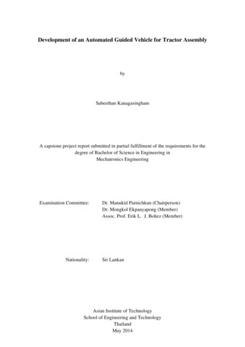
EC1166 (DFBP)LC0503 (RWP)The procedure requires a few steps. The chip is first carefully positioned on the PCB usingtweezers. Once the pins are correctly located on the printed copper strips, a few drops ofsolder are put on two corners of the IC to hold it temporarily. Subsequently, large beads ofsolder are melted on all pins of the chip using the soldering gun at temperature around 400degrees Celsius. Finally, excess amount of solder is cleaned off from the legs of IC chip usingclay.It is important not to heat the IC for more than 5 seconds since the high temperature caninternally fry the chip.2.2.1.5 Schematic DiagramThe mechanism running inside the Sensor Board can be explained better with the help of aschematic diagram below.Fig 2.8 - Schematic Diagram of Sensor Board(Source: DFBP Textbook from SP Blackboard)18
EC1166 (DFBP)LC0503 (RWP)2.2.1.6 How It WorksThe five Infra-Red (IR) Emitting Diodes (L31 – L35) perform as light sources. They aresupplied with 12 Volts on their positive end in series and the negative end is connected tothe ground through transistor (T31). The transistor is forward –biased during operation sothat current can flow through the IR Emitting Diodes.Infra-Red rays are emitted from the diodes during the process. Those rays are bounced backwhen a reflective surface is present below. The reflected rays, at the right angle, enter theIR phototransistors (D31 – D35).The phototransistors act as light sensors. When rays strike the phototransistors, currentflows through the respective resistors from R31 to the ground. Pins (3, 4, 7, 8, 13) from IC31measure voltage from each of the 5 LEDs with respect to the ground. If voltage is higherthan 2.4 volts, the respective output from IC31 shows a logic 1, or 5V. Else, it shows logic 0,or 0V.The signal is then sent to the Microcontroller Board.When connected to the Microcontroller Board, the pin 1 from J32 is supposed to provide 5Volts and pin 4 is supposed to supply 12 Volts. The other two pins (2 and 3) are Ground.Pin 1 (5V) provides potential for the 5 IR Detectors which are connected in Parallel, so thateach of the five will consume 5 Volts. Therefore, the output of these 5 LEDs can range from0V to 5V, proportionately to the Infra-Red waves they detect.Pin 4(12V) provides potential for the 5 IR Emitters which are connected in Series. Each of theemitters will consume around 1.7V to 2.2V according to the conditions.On the J31 connector, pin 1 through 5 carry signals from the IC according to the 5 LEDs. Pin7 provides a clock frequency, which is 1.0000 KHz, to the IC chip. Pin 8 is called Enable,which means it provides 5V, or logic 1, at all times.2.2.1.7 Finalized BoardA finished Sensor Board functions as follows. The IR Emitters emit Infra-Red rays wheninstructed from the Microcontroller Board according to the program. When the AGV is on itspath with reflective strips, IR rays will reflect back to IR Detectors which allows current toflow through them to the resistors, which in turn set potential (according to Ohm’s Law).The IC chip measures the voltage, and generates logic output, so that the Microcontrollercan understand what the detectors are reading.A Sensor Board functioning as such appears the same way as the one in the followingpicture.19
EC1166 (DFBP)LC0503 (RWP)(A)(B)Fig 2.9(a,b) – A finished Sensor Board ready for troubleshooting(Photo by: Kyi Hla Win)2.2.2 Motor driver boardThe motor driver board plays an essential role in the AGV. It controls the movement of theAGV as well as the up and down movement of forklift.Fig 1 shows placement and orientation of the different components required for the motorboard to function.20
EC1166 (DFBP)LC0503 (RWP)Fig 2.10 - Motor Board Artwork(Source: DFBP Textbook from SP Blackboard)To begin with, each component has to be brought individually from shops located in Sim Limtower.After the components were bought, our team has to solder each component with precisiononto the printed circuit board.This is a delicate process as poor solder joints may cause short circuits which will in turndamage the components or cause the circuit to malfunction.When there is a short circuit or damaged components in the circuit, the motor driver mayperform undesired operations which may cause further problems.Fig 2 shows the motor driver board after all the necessary components are soldered ontothe printed circuit board.21
EC1166 (DFBP)LC0503 (RWP)Fig 2.11 - Finalised Motor Board(Photo by – Garry Han)2.2.2.1 Components and description IC26, IC27 – L298 Dual Full bridge driverUsed to drive bipolar stepper motor IC 24, IC 25- L297 Stepper motor controllersUsed to control the drive of the stepper motor with half-step or normal step. IC21 – A3953 Full bridge PWM motor driverUsed to control the operation of the DC motor. C20, C24 - 47uF/16v C21, C22 – 0.1uF/50v22
EC1166 (DFBP)LC0503 (RWP) C23 – 820pF/50v R21-R24 – 1ohm 1 wattR20 – 22Kohm ¼ wattR25 – 27Kohm ¼ wattR26 – 0.47ohm 1 watt(Pictures Source: Google Image Finder – images.google.com)2.2.2.2 How it worksIC 24 and IC 25 are supplied with Vcc 5 volts to pin 12 and ground to pin 2. These 2 IC areused to provide signal to drive the stepper motor. The signals are sent to outputs A, B, C, D,pin 4,6,7,9 respectively.IC 26,27 are supplied with Vcc 5 volts to pin 9 and 12 volts to pin 4.While ground isconnected to pin 8. These 2 IC are used to drive the stepper motors. The signals are sent tooutputs 1,2,3,4, pins 2, 13, 3, 14 respectively.IC22 and IC 23 serve as diodes to protect the circuit from shortage.Each of these IC works together in order to drive a stepper motor. This is the reason whythere are 2 sets for each type of IC used.Outputs from pins ABCD are sent to IN1, IN2, IN3, IN4 of IC 26, iC27. The signal is thenprocessed and sent from OUT1, OUT2, OUT3, OUT4 to pin 2, 10, 7, 15 respectively.The signal is then transferred to J20, where the 4 way pins of the stepper motor isconnected.The motor will turn according to the signal received.IC 24 is used to control the operation of the DC motor. IC 24 is supplied with VCC to pins 1,2, 6.The DC motor is controlled by the signal coming from pin7 and pin 8, phase and enablerespectively.These 2 pins use the combination of logic signals to control the output. To control the dcmotor to turn in forward motion, enable has to be set to logic low while phase is set to logic23
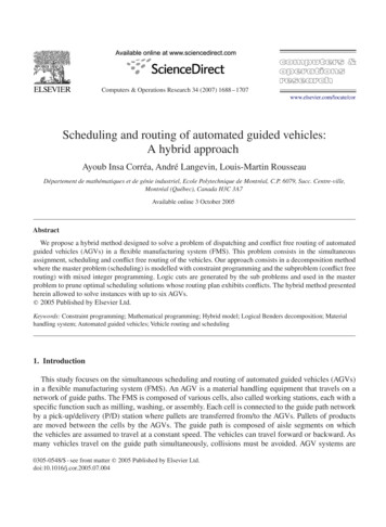
EC1166 (DFBP)LC0503 (RWP)high. For a reverse motion, both enable and phase are to set to logic low.2.2.2.3 Hardware testingAfter soldering is completed, our team checks for poor solder. If there are poor solders, ourteam will de-solder the particular section and solder it back again.2.2.2.4 Manual TestWhen checking is done, motor board is tested manually to check if it is working.First, the following equipments are needed:1: Multimeter2:Oscilloscope3:Power Supply4:Signal GeneratorTo test if the motor board can control the stepper motor, the following has done.First, connect J7 of the microcontroller board to J23 and J22 of the motor board using a 4way wire. Ensure the 5 volt is correctly connected to J23 and 12 volt is correctly connectedto J2. If these two volts are switched, the circuit may be damaged by the high voltage.This action is to pass current to the motor board to activate the board.Then use the probes to connect reset and enable pins of J26 from the motor board to the 5volts pin of J6 on the microcontroller board.Using probes again, connect the 2 clock pins, left and right respectively, of J26 on the motorboard to ground on J6 of the microcontroller board.This is to activate the individual stepper motors.In order to test if the wheel’s direction of turning can be changed, our team connects rightdirectional pin and left directional pin of J26 of the motor board to ground of J6 on themicrocontroller board.This ends the manual connecting sequence of the two boards.Then turned on the power supply and adjust the voltage to 12 volts and current to 1 ampereand connected the red and black wire of the microcontroller board to live and ground of thepower supply respectively.After connecting the power supply, we connect a test probe to the oscilloscope. Connect24
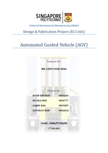
EC1166 (DFBP)LC0503 (RWP)the crocodile clip to common ground and begin probing each pins to check for desiredoutputs.Check the output pins of IC24, IC25, IC26, IC27.Refer to Fig 2.12 for the schematic diagram for respective pins to be probed.Fig 2.12 Motor Board Schematic Diagram (Source: DFBP Textbook from SP Blackboard)Pin 4, 6, 7, 9 of IC24 and IC25 has to be logic 1, which is 2.4 5 volt. Pin 2, 13, 3, 14 of IC26and IC27 has to be 2.4 5volt. While pins 4,3,2 of J20 and J21 has to be 2.4 5volt.Pin 1 of J20 and J21 has to be 0volt.25
EC1166 (DFBP)LC0503 (RWP)If the outputs are correct, the motor board is capable of controlling the stepper motor.This ends the manual testing of the stepper motor.To test if the motor board can control the DC motor, these steps are taken.Connect pin 1 of J24, enable, to pin 2 of J2. Connect pin 2 of J24,phase, to pin 1 of J2.To test for forward slow current- decay mode, probe enable t
Automated Guided Vehicle (AGV) Prepared For: MR. CHOY FOOK SENG . Prepared By: KYAW SOE HEIN 0856566 KYI HLA WIN 0856777 GARRY HAN 0847007 AYE MYAT MON 0856818 . and electronic parts of an automated vehicle. The critical part is to understand the concepts of design, drawings, process planning, machining