Transcription
FLAME SAFEGUARD & COMBUSTION CONTROLSPrefaceThis manual provides the basic principles ofoperation and application of Fireye flamesafeguard controls. It is not intended to improveon, or replace, any of the technical bulletins thatare factory shipped with the controls.Field technicians preparing for a wider base ofknowledge in this field may benefit significantlyfrom this document.Although this manualshould prove beneficial at various levels, it isdirected towards service technicians andoperating personnel which service theequipment described in this manual on a regularbasis.However, this manual presupposes the readerpossesses an adequate background in thefundamentals of burners, heaters and boilersincluding utilization of the various fuels burnedand the control systems associated with thistype of equipment.The content of this manual outlines the Fireye,flame safeguard (FSG) environments as well asthe principles of operation and installation of thevarious flame detector devices and theirassociated control systems.Page 1
FLAME SAFEGUARD & COMBUSTION CONTROLSFlame Safeguard . 3History . 3Types. 4Commercial . 4Industrial. 4Common Terms In Flame Safeguard .22Prepurge .22PTFI .22MTFI.22Post Purge .22Combustion . 4Burners. 5Fuels. 6Flame . 7Types Of Pilot Burners .22Interrupted Pilot.22Intermittent Pilot .22Standing Pilot.22Flame Detection . 7Flame Safeguard Controls .22Operating Interlock Circuit .22Running Interlock Circuit.22Flame Rod . 7Installation & application . 9M Series Flame Safeguard Controls .23Radiation Properties of Flames . 10Visible Light Flame Detectors. 11Application & Installation . 11Ultra Violet flame Detection . 12UV Tube . 12Non Self-Check . 13Self-Check. 14Wiring UV Scanners. 14Infrared Flame Detectors. 15Flame Flicker. 15IR Cell Saturation . 16Installation Tips . 16Wiring IR Scanners . 16Trouble Shooting & Testing of Scanners . 17Flame Signal Measurement . 17Hot Refractory Saturation Test . 17Hot Refractory Hold-In Test . 17Ignition Spark Sensing Test . 17Ignition Interference Test . 18Pilot Turn-Down Test . 18Tips For Flame Detector Mounting AndEnclosures . 19Flame Rod. 19Optical Detectors. 19Infrared Scanners. 19Ultra Violet Scanners . 19Swivel Mounts . 20Sealing Unions . 20Purging/Cooling Air . 20Enclosures . 21UVM & TFM Controls.23M Series II Controls .24Micro M Series Controls .26M Series Wiring Schematics.28M Series 100 Control Sequence.32M Series 200 Control Sequence.33M Series 500 Control Sequence.34Trouble Shooting M Series .35M Series Typical Application.37M Series Typical Application.38D Series Flame Safeguard Controls.39Assembly .40Before Installing the Control .40LED Indicator Lights .41Flame Signal Strength .41Run Check Switch.41D Series Wiring Schematics .42D10/20 Series Control Sequence .43D30 Series Control Sequence .44Trouble Shooting D Series.45D Series Specifications .46Flame Monitor .47Specifications.47Amplifier Modules .48Programmer Modules .49Dipswitch Settings.50Wiring Schematics .52Supply Voltage Tolerance.553 - P Circuit Tolerance .55Grounding Methods .56Display Module .58EPD Style Programmers.59Flame Monitor Messages .60Logic Flow Diagrams .62Trouble Shooting Flame Monitor .65Page 2
FLAME SAFEGUARD & COMBUSTION CONTROLSThe control of fuel fired equipment can bedivided into two categories; “Flame SafeguardControl” and “Combustion control”.FlameSafeguard Control provides operation andmonitoring for safety in meeting fuel-handlingand equipment design limitations. CombustionControl provides operation and monitoring for aburner’s capacity by varying its output based onprocess demand.FLAME SAFEGUARDBy definition, the term Flame Safeguard (FSG)covers all aspects of “safety” in operation of fuelfired equipment. This includes the flamedetection device used to sense the presence offlame, the fuel safety shut-off valves, fuel safetylimits, auxiliary safety limits, sequencing andtiming relays and any other controls used inconjunction with the burner safety controlsystem.The main functions performed by a flamesafeguard system are:1.Safely starting and stopping of the burnereither, manually, semi-automatically, orautomatically.2.Enforcing proper event-sequencing duringstarting and stopping.3.Performing flame supervision via sensing andreacting to presence or absence of flame.4.Guarding the system against conditionsoutside of the equipment’s design limitations.HISTORYAround the turn of the 20th century, FSG waslimited to mechanically shutting off the fuel in theevent of a flame failure. There was no way ofdetecting flame, so the weight of the unburnedfuel, such as fuel oil, was used as a means ofdetection. The fuel oil, when the flame went outended up being collected in the furnace area, oroverflowed into an exterior container, where itsweight was used to cause a lever to close thefuel supply valve.As electricity began to play a role in the industry,around the 1930’s, giving rise to electricallycontrolled valves, electromechanical ways ofdetection were also developed. Bimetal andthermocouple type instruments were developedwhich reacted to the temperature in flue gasesor to direct radiation from the flame and many ofthese are still in use today.The bimetal and thermocouple method, althoughsuitable for low capacity applications, proved tooslow for high fuel input type applications and theFig. 1 Fireye “P” Series control.Model: 26RJ8search continued for faster means of flamefailure detection.It was found that a gas flame envelope couldcarry a small electrical current.Thischaracteristic led to the development of a newand electronic type of flame detection. A rod(flame rod) was inserted into the flame and theconductivity of the flame, if present, could bemeasured. Although this system eliminatedreaction time issues, it proved unreliable. Anyhigh resistance short in the sensing circuit couldalso simulate flame. This was later overcome bythe introduction of the “flame rectification” circuitwhereby the alternating current (AC) has to berectified to direct current (DC) in order to beaccepted as flame signal. This system is stillwidely in use today.Both the bimetal orthermocouple and flame rod systems requiredirect contact with either the flue gases or flameenvelope and it was not until the mid 1940’s thatoptical flame detection became a reality. Thefirst optical detector was a photocell to sensevisible light in oil burners, followed by infra reddetectors in the 1950’s and ultra violet detectorsin the 1960’s. Ongoing developments continuePage 3
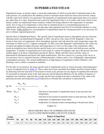
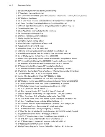
FLAME SAFEGUARD & COMBUSTION CONTROLSto fine-tune these sensors to meet the everincreasing demands for safety in the industry.TYPESThere are many types of flame safeguardcontrols designed for use in sidential FSG controls generally rely on athermocouple inserted into the pilot flame. Theheat in the thermocouple generates just enoughvoltage to hold in a magnetic coil, which holds ina spring-loaded plunger inside the automatic gasvalve allowing gas flow to the burner. Theplunger is manually pushed in and the pilot lit,followed by a short period of time for thethermocouple to start generating enough currentto hold in the plunger. This system requires thatthe pilot flame is on at all times whether theburner is on or off. As this wastes fuel, moremodern residential equipment utilize anautomatic pilot light on-demand via sparkignition combined with flame-rod flamedetection.purge, low fire start, check fuel-valve closed,post-purge and other functions.Both residential and commercial FSG productsare designed with single burner appliances suchas furnaces and boilers in mind.Theseappliances require that the flame safeguardcontrol properly sequences the operation of theburner system: energizing the combustion airblower motor, purging the combustion chamberof any combustibles, opening pilot fuel valve andenergizing ignition, establishing main flame andmonitoring flame for failure. All componentsmust be energized in the proper sequence toprevent unburned fuel from accumulating in theequipment where it could cause a hazardouscondition. It continuously senses presence orabsence of flame while controlling the operationand sequence of all components on the burnerin the proper order.Industrial FSG controls generally operate in amulti burner environment. This environmentplaces different demands on flame safeguardcontrols, the most important of which is theability of the flame detection system todiscriminate between its targeted flame andother flames sharing the combustion chamber.Programming and sequencing logic in a multiburner appliance generally resides in a burnermanagement system (BMS) which may be in theform of a programmable logic controller (PLC) ora relay logic panel, or a combination of both. Aseparate Fireye bulletin “Flame SafeguardControls in Multi Burner Environments”,publication WV-96, deals with this subject indetail.COMBUSTIONFig 2 Burner control panel with Fireye FlameMonitor and “First-out” expansion module.Commercial FSG controls are divided into“Primary” and “Programming” controls. Thedistinction between primary and programming isthat primary controls have a minimum inoperating parameter logic, such as safe startcheck, trial for ignition, flame failure responsetime and lock-out functions. This makes themideally suitable for appliances such as smalldirect light-off (no pilot burner) burners andburners for make-up air heaters, direct orindirect fired.Programming controls operate with manyadditional functions such as pre-purge, proof ofCombustion or burning, is a rapid combination ofoxygen with fuel, resulting in release of heat.The oxygen comes from air. Air is about 21%oxygen and 78% nitrogen by volume. Most fuelscontain carbon, hydrogen, and sometimessulfur. A simplification of combustion could belisted in the following three processes:carbon oxygen carbon dioxide heathydrogen oxygen water vapor heatsulfur oxygen sulfur dioxide heatPage 4
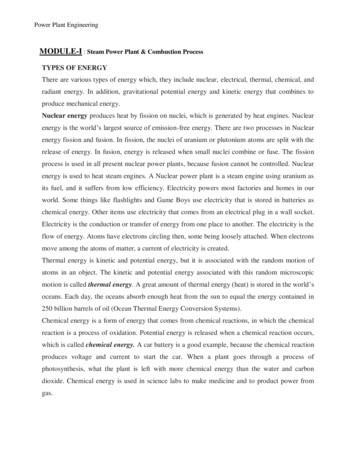
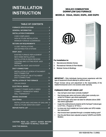
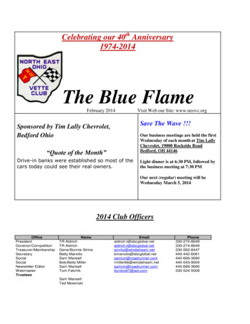
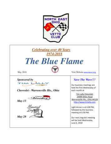
FLAME SAFEGUARD & COMBUSTION CONTROLSThe above three products of combustion arechemical compounds. They are made up ofmolecules in which elements are combined incertain fixed proportions.As per the law ofscience, matter is neither created nor destroyedin the process of combustion, and the heat givenoff in any combustion process is merely excessenergy which the molecules are forced toliberate because of their internal make-up.Stoichiometric combustion is obtained when nofuel or air goes unused during the combustionprocess. Mixing and burning exactly the rightproportions of fuel and oxygen so nothing is leftover does this. Combustion with too much(excess) air is said to be lean or oxidizing. Theexcess air or oxygen plays no part in thecombustion process. In fact it reduces theefficiency. The visual effect is a short and clearflame. Combustion with too much fuel is saidto be rich or reducing, producing incompletecombustion. The visual effect is a long andsometimes smoky flame.The oxygen supplyfor combustion generally comes from theambient air. Because air contains primarily(78%) nitrogen, the required volume of air isgenerally much larger then the required volumeof fuel. Primary air is air that is mixed with thefuel before or within the burner's fuel deliverysystem. Secondary air is usually brought inaround the burner's fuel delivery system andspun through a diffuser or turning vane systemin order to optimize air-fuel mixing. Tertiary air isair brought in downstream of the secondary airand is sometimes used to control the shape ofthe flame envelope, and/or to control flametemperature on low-NOx burners.achieving optimum results in any of thesefunctions. The following lists some variations ofburner types found:BURNERSFig. 3 Principle parts of a forced draft burner.a)a)b)c)d)e)Gaseous fuel fired:Natural draft burnerInspirating burnerBalanced draft burnerInduced draft burnerForced draft burnerLiquid fuel fired: (forced or balanced draft)a) Mechanically atomized.b) Air atomizedc) Steam atomizedFinal fuel delivery and combustion-air & fuelmixing varies dependent on the burner types asper the following examples:a) Gun type (gas or oil)b) Cane (spud) type (gas)c) Ring type (gas)d) Rotary cup type (oil)Burners are a simple device to convert fossilfuels into useable heat energy. The primaryfunctions of burners are:a) Controlled fuel delivery.b) Controlled combustion-air deliveryc) Controlled fuel and air mixing.d) Controlled and reliable ignition.e) Evacuation of products of combustion.f) Controlled emissions.Regardless of fuels fired, burners must reliablyperform all functions. Choices of fuels burnedand type of burner affect the difficulties inFig. 4 Forced draft burner.Page 5
FLAME SAFEGUARD & COMBUSTION CONTROLSA burner must be equipped with a monitoringand control system to assure safe and reliableoperation throughout itsintended use.Complexity of this system is in relation tocomplexity of the process at hand and can varyfrom a single burner firing a single fuel, to a multiburner environment where many burners areoperating into a common combustion chamberand a multiple choice of fuels are burned. Thelarger the burner input, or heat release of aburner, does not necessarily mean the morecomplex the monitoring and control systemneeds to be.Conditions effecting complexity of controlsystems for burners are generally stipulated by:a) Type of process.b) Type of burner.c) Multi or single burner environment.d) Multi or single fuel operation.e) Safety hazard of fuel burnedf) Local codes and standards.g) Redundancy and reliability factors.h) Continuous or intermittent burner operation.Technological advances in recent years inparticular microprocessor based hardware, hasmade it important that only qualified ation hardware used in today's burneroperating and safety systems. Componentsmaking up the system for monitoring and controlof burners are subject to standards set by localauthorities.FUELSMost fuels are mixtures of chemical compoundscalled hydrocarbons. When burning these fuels,the final products contain carbon dioxide andwater vapor unless a shortage of oxygen existsin which case the products of combustion maycontain carbon monoxide, hydrogen, unburnedhydrocarbons and free carbon. Heat availablefrom fuels is measured in Btu/lb or Kcal/kg(Btu/gal or Kcal/l for fuel-oil). Natural gas fuel isthe most straightforward fuel to use. It requiresno special handling in filtering, drying, heating,etc.On the other hand, the efficiency inutilization of fuel oils depends to a large extentupon the ability of the burner system to atomizethe oil and mix it with combustion-air in thecorrect proportions. Heavy fuel oils are usuallypre-heated with steam. Tank heaters may raiseheavy fuel-oil temperatures sufficiently to reduceits viscosity in order to facilitate pumping Coke l (8,583)Oil 9(9,720)14,03012,9003,5003,100CoalTable 1 Comparative heating values for typicalfuels.In order to burn a liquid fuel, most burnersatomize the liquid. Atomization is the formationof the smallest possible droplets. This isrequired in order to expose as much surfacearea of the fuel as possible within the flameenvelope.Steamatomizationcanbeaccomplished by projecting steam tangentiallyacross jets of oil at the oil nozzle, resulting in aconical spray of finely divided oil after themixture leaves the nozzle. Air atomization isaccomplished by using air as an atomizing agentin an arrangement such as a proportioninginside-mixing-type oil burner using low-pressureair as an atomizing agent. Large capacity oilburners use two steps to get the oil combustible:atomization and vaporization. Vaporizationconverts oil from the liquid to the Vapor State byapplication of heat at the flame-front.By firstatomizing the oil into millions of tiny droplets, theexposed surface area is increased many timesand the oil can vaporize at its highest rate. Forgood atomization and vaporization, a largevolume of air must be initially mixed with the oilparticles. Mechanical atomization - atomizationwithout the use of either air or steam - issynonymous with pressure atomizing.Thenozzle used in mechanical atomizing consists ofPage 6
FLAME SAFEGUARD & COMBUSTION CONTROLSa system of slots tangential to a small inner whirlchamber followed by a small orifice. In passingthrough the slots, the liquid volume is increased.The high velocity prevailing in the whirl chamberin a tangential direction imparts a centrifugaleffect that forces the oil against the walls of thenozzle. It then passes through the orifices in thenozzle tip and into the combustion chamber,fanning out into a cone shaped spray of verysmall particles.FLAMEA flame is merely a zone within which thecombustion reaction takes place at a rate thatproduces visible radiation. A flame-front is thecontour along which the combustion starts (thedividing line between the fuel-air mixture and thecombustion process). In stable flames, theflame front appears to be stationary. The flameis actually moving towards the burner-nozzle(s)at the same speed that the fuel-air mixture isleaving the burner. Wide ranges of feed rangesexist in a wide range of burner designs. In orderto select the most suitable flame detectionhardware, it is necessary to know the basiccharacteristi
separate Fireye bulletin “Flame Safeguard Controls in Multi Burner Environments”, publication WV-96, deals with this subject in detail. COMBUSTION Combustion or burning, is a rapid combination of oxygen with fuel, resulting in rel