Transcription
FEBRUARY 2019LRFD BRIDGE DESIGN5-15. CONCRETESTRUCTURESReinforced and prestressed concrete are used extensively in bridgeprojects. In addition to general design guidance and information ondetailing practices, this section contains three design examples: a threespan reinforced concrete slab superstructure, a 63 inch pretensionedI-beam, and a three-span post-tensioned concrete slab superstructure.5.1 MaterialsFor most projects, conventional materials should be specified. Standardmaterials are described in two locations: MnDOT Standard Specificationsfor Construction (MnDOT Spec.) and Bridge Special Provisions.If multiple types of concrete or reinforcement are to be used in a project,it is the designer’s responsibility to clearly show on the plans the amountof each material to be provided and where it is to be placed.5.1.1 ConcreteMnDOT Spec. 2461 identifies and describes concrete mix types. Based ontheir strength, location of application, and durability properties, differentmixes are used for various structural concrete components. Table 5.1.1.1identifies the standard MnDOT concrete mix types to be used for differentbridge components.The four or five characters used to identify a concrete mix provideinformation on the properties of the mix. The first character designatesthe type of concrete (with or without air entrainment requirements). Thesecond character identifies the grade of concrete. Each letter is associatedwith a different cement-void ratio. The third character in the label is theupper limit for the slump in inches. The fourth character identifies thecoarse aggregate gradation. The fifth character, if present, identifies thetype of coarse aggregate to be used. Note that there are two exceptionsto the above: job mixes (JM) for box girders, and high performanceconcrete (HPC) mixes for bridge decks and slabs.For HPC mixes, the first and second characters follow the descriptionabove. For monolithically poured decks, these are followed by either “HPCM” or “LCHPC-M” (where the LC designates low cement). For decks thatwill receive a separate wearing course, these are followed by either “HPCS” or “LCHPC-S” (where the LC designates low cement). For job mixes,the first character designates the type of concrete as above, but is followedby “JM” for mixes that will be determined by the Contractor.In general, the standard concrete design strength is 4 ksi, and air entrainedconcretes are to be used for components located above footings and pilecaps to enhance durability.
FEBRUARY 2019Table 5.1.1.1LRFD BRIDGE DESIGN5-2Design Concrete Mix SummaryLocation/ElementCofferdam sealsCast-in-place concrete piles andspread footing leveling padsDrilled shafts and rock socketsFootings and pile caps, except not for partiallyexposed abutment footings behind MSE walls.MnDOT Concrete MixDesign CompressiveMaximumDesignationStrength (ksi)Aggregate Size 24.01½*4.01Abutment stems, wingwalls, pier columns, pierstruts, and pier caps. Also includes partiallyexposed abutment footings behind MSE walls.Integral abutment diaphragms andSame mix as used inpier continuity diaphragmsdeckPretensioned superstructures1W82 or 3W82Cast-in-place and precast box girders3JMMonolithic decks and W825.0 or higher1*3YHPC-M, 3YLCHPC-Mor 3Y42-M3YHPC-S, 3YLCHPC-Sconcrete wearing courseor 3Y42-Smoment slabs, and approach panelsConcrete wearing courseMSE wall panels, PMBW blocks, and noisewallpanelsCast-in-place wall stemsPrecast box culverts, arches,and 3-sided structures16.0 or higherDecks and slabs that will receive a 2 inchBarriers, parapets, medians, sidewalks,5.0 – 9.0 at final4.5 – 7.5 at initial5/8* For determination of sxe per LRFD 5.7.3.4.2, use max aggregate size ag ¾”Reinforced Concrete SectionsBase concrete modulus of elasticity computations on a unit weight of 0.145kcf. Use a unit weight of 0.150 kcf for dead load calculations.For structural modeling (determining design forces and deflections), usegross section properties or effective section properties. For redundantstructures with redundant and nonprismatic members, model withnonprismatic elements.[5.4.2.4]For reinforced concrete elements, use: Ec 120,000 K1 wc 2 f'c0.33
FEBRUARY 2019LRFD BRIDGE DESIGN5-3For checks based on strength (design of reinforcement, maximumreinforcement), use conventional strength methods (reinforcementyielding, Whitney equivalent stress block, etc.).For checks based on service loads (fatigue, crack control, etc.), use crackedsections with reinforcing steel transformed to an equivalent amount ofconcrete.Prestressed Concrete ElementsWhen computing section properties, use a modular ratio of 1 for theprestressing strands.For pretensioned beams (M, MN, MW, and RB) fabricated with highstrength concrete (greater than 6.0 ksi), compute the modulus of elasticitywith the ACI 363 equation below:Ec 1265 f'c 1000(where f’c and Ec are in ksi)For all other pretensioned and post-tensioned elements, compute themodulus of elasticity using AASHTO LRFD Equation 5.4.2.4-1, with K1 1and wc 0.150 kcf.For both pretensioned and post-tensioned elements, use a unit weight of0.155 kcf for dead load calculations.Table 5.1.1.2 summarizes concrete properties for analysis and design:
FEBRUARY 2019LRFD BRIDGE DESIGN5-4Table 5.1.1.2Concrete PropertiesParameterEquation/ValueReinforced Concrete Elements:wc 0.145 kcf for calculation of EcUnit Weightwc 0.150 kcf for dead load calculationPretensioned and Post-tensioned Elements:wc 0.150 kcf for calc. of Ec (except pretensioned beams)wc 0.155 kcf for dead load calculationPretensioned Beams:Ec (ksi) 120,000·K1·wc2·f’c0.33Modulus of ElasticityEc (ksi) 1265· f’c 1000where f’c 6 ksiwhere f’c 6 ksiAll Other Concrete Elements:Ec (ksi) 120,000·K1·wc2·f’c0.33Thermal CoefficientShrinkage StrainPoisson's ratio5.1.2 ReinforcingSteel c 6.0 x 10⁻⁶ in/in/ FReinf. Conc.: εsh 0.0002 @ 28 days and 0.0005 @ 1 yearPrestressed Concrete: per LRFD Art. 5.4.2.3 0.2Reinforcing bars shall satisfy MnDOT Spec 3301. ASTM A615 Grade 60deformed bars (black or epoxy coated) should be used in mostcircumstances. In some cases, Grade 75 stainless steel bars will berequired in the bridge deck and barrier (see Tech. Memo No. 17-02-B-01Requirements for the Use of Stainless Steel Reinforcement in Bridge Decks& Barriers). Use fy 75 ksi when designing with stainless steel bars.Always use stainless steel (Grade 75) for the connecting bar betweenapproach panel and end diaphragm at integral and semi-integralabutments.In specialized situations and with the approval of the State Bridge DesignEngineer, welding to reinforcement may be used. ASTM A706 Grade 60bars must be used for applications involving welding.The modulus of elasticity for mild steel reinforcing (Es) is 29,000 ksi.All reinforcement bars, except stainless steel bars and bars that are entirelyembedded in footings, shall be epoxy coated. Note that for footings thatare not entirely buried, such as for abutments behind mechanicallystabilized earth walls, reinforcing bars must be epoxy coated.
FEBRUARY 2019LRFD BRIDGE DESIGN5-55.1.3Reinforcement BarCouplersContractors select reinforcement bar couplers that meet the requirementsstated in MnDOT Spec. 2472.3.D.2.In general, the couplers need to: Provide a capacity that is 125% of the nominal bar capacity. Be epoxy coated. Satisfy fatigue testing requirements of NCHRP Project 10-35 (12 ksi).5.1.4 PrestressingSteelUncoated low-relaxation 7-wire strand or uncoated deformed, highstrength bars are acceptable prestressing steels. Strands shall conform toASTM A416. Bars shall conform to ASTM A722.Use the following properties for prestressing steel:Tensile strength: fpu 270 ksi for strandsfpu 250 ksi for barsYield strength:fpy 243 ksi for strandsfpy 120 ksi for barsElastic Modulus: Ep 28,500 ksi for strandsEp 30,000 ksi for barsStandard 7-wire prestressing strand area, Aps:3/8" diameter strand:0.085 in 2 /strand1/2" diameter strand:0.153 in 2 /strand0.6" diameter strand:0.217 in 2 /strand5.1.5Post-tensioningHardwareFor post-tensioned concrete bridges, open ducts must be used for tendonpassageways through the superstructure. Longitudinal ducts are typically3 to 4 inches in diameter and must be sufficiently rigid to withstand theloads imposed upon them. The preferred material for longitudinal ducts iscorrugated plastic (HDPE). Transverse ducts are typically smaller,containing from 1 to 4 strands. Because the transverse ducts are relativelyclose to the top of the deck with heavy applications of corrosive de-icingchemicals, corrugated plastic ducts are required. The anchor head istypically galvanized or epoxy coated based on project needs. Discuss theprotection requirements with the State Bridge Design Engineer.Tendon anchorage devices are required at the ends of each duct.Anchorages should be shown and indicated on the drawings. Detailing isunnecessary because the post-tensioning supplier will provide these detailsin the shop drawings for the post-tensioning system. Designers mustconsider the local zone anchorage reinforcement (typically spiralreinforcement) provided by potential suppliers to allow adequate room forthe general zone reinforcement designed and detailed in the bridge plans.
FEBRUARY 20195.2 ReinforcementDetailsLRFD BRIDGE DESIGN5-6Practices for detailing a variety of reinforced concrete elements arepresented in this section. These include standard concrete cover and barspacing dimensions, plus a variety of specific design and detailinginstructions.Reinforcing details are intended to provide a durable structure withstraightforward details. Details must be constructible, allowing steel to beplaced without undue effort, and provide adequate clear cover andadequate space between reinforcement to permit the placement ofconcrete.5.2.1 MinimumClear Cover andClear SpacingThe minimum clear cover dimension to reinforcement varies with thelocation in the bridge. It varies with how the component is constructed(precast, cast in forms, cast against earth) and the exposure the elementhas to de-icing salts. In general, minimum covers increase as control overconcrete placement decreases and as the anticipated exposure to de-icingsalts increases. Following is a list of structural components and thecorresponding minimum clear cover. For components that are not listed,a 2" minimum clear cover is required unless it is shown differently in theBridge Office standards.FoundationsTop Bars Minimum clear cover is 3 inches.Bottom Bars, Spread Footing Minimum clear cover to the bottom concrete surface is5 inches. Minimum clear cover to the side concrete surface is 3 inches.Bottom Bars, Pile Cap w/ Pile Embedded 1 foot Rest directly on top of trimmed pile.Bottom Bars, Pile Cap Alone or Where Pile Cap is Cast Against a ConcreteSeal, w/ Pile Embedded More Than 1 foot Minimum clear cover is 3 inches to bottom of pile cap.Abutments, Piers, and Pier Crash Struts Standard minimum clear cover for all bars is 2 inches (vertical andhorizontal). At rustications, the minimum horizontal clear cover varies with the sizeof the recess. For recesses less than or equal to 1 inch in depth andless than or equal to 1 inch in width, the minimum clear cover is 1.5inches. For all other cases, the minimum clear cover is 2 inches. Minimum clear distance between reinforcement and anchor rods is2 inches.
FEBRUARY 2019LRFD BRIDGE DESIGN 5-7In large river piers with #11 bars or larger that require rebar couplers,minimum clear cover to bars is 2.5 inches.Decks, Slabs, Sidewalks, and Raised MediansTop Bars, Roadway Bridge Deck or Slab, Sidewalk, and Raised Median Minimum clear cover for epoxy coated bars to the top concretesurface is 3 inches. Minimum clear cover for stainless steel bars to the top concretesurface is 2½” inches for monolithic decks, 3” for partial depthdecks with a wearing course, and 4” for concrete box girder decks. Minimum horizontal clear cover is 2 inches. In the bridge plan,detail bars with an edge clear cover of 2 inches, but compute barlength assuming 2½” clear.Top Bars, Pedestrian Bridge Deck Minimum clear cover to the top concrete surface is 2 inches.Bottom Bars, Deck Minimum clear cover to the bottom concrete surface is 1 inch. Minimum horizontal clear cover from the end of the bar to the faceof the concrete element is 4 inches. Minimum horizontal clear cover from the side of a bar to the face ofthe concrete element is 2 inches.Bottom Bars, Slab Minimum clear cover to the bottom concrete surface is 1.5 inches. Minimum horizontal clear cover from the end of the bar to the faceof the concrete element is 4 inches. Minimum horizontal clear cover from the side of a bar to the face ofthe concrete element is 2 inches.5.2.2 ReinforcingBar ListsFor numbering of reinforcing bars, the first character is a unique alphacharacter for the given structural element. The first one or two digits ofthe bar mark indicate the U.S. Customary bar size. The last two digits arethe bar’s unique sequential number in the bar list for that substructure orsuperstructure unit. A suffix “E” indicates the bar is epoxy coated, "G"indicates the bar is galvanized, “S” indicates the bar is stainless steel, “Y”indicates a Grade 75 epoxy coated bar, and “Z” indicates a Grade 75 plainbar.For example, an A603E bar could be decoded as follows:A – 6 – 03 – EEpoxy coated barBar number 3 for this structural unitSize of bar is #6Abutment
FEBRUARY 2019LRFD BRIDGE DESIGN5-8The cross-sectional areas, diameters, and weights of standard reinforcingbars are provided in Table 5.2.2.1.Table 5.2.2.1Reinforcing Steel Sizes and PropertiesArea of Bar(in 2 )Diameter of BarWeight of BarBar 61.4105.313#142.251.6937.650#184.002.25713.60U.S. CustomaryTable 5.2.2.2 lists the reinforcing steel area provided (per foot) for differentsized bars with different center to center bar spacings.
FEBRUARY 2019LRFD BRIDGE DESIGN5-9Spacing of Bars in Inches(in)NominalDiameterNumberBar SizeTable 5.2.2.2Average Area per Foot Width Provided by Various Bar Spacings (in2/ft)33.544.555.5678910111230.3750.44 0.38 0.33 0.29 0.26 0.24 0.22 0.19 0.17 0.15 0.13 0.12 0.1140.5000.80 0.69 0.60 0.53 0.48 0.44 0.40 0.34 0.30 0.27 0.24 0.22 0.2050.6251.24 1.06 0.93 0.83 0.74 0.68 0.62 0.53 0.47 0.41 0.37 0.34 0.3160.7501.76 1.51 1.32 1.17 1.06 0.96 0.88 0.75 0.66 0.59 0.53 0.48 0.4470.8752.40 2.06 1.80 1.60 1.44 1.31 1.20 1.03 0.90 0.80 0.72 0.65 0.6081.0003.16 2.71 2.37 2.11 1.90 1.72 1.58 1.35 1.19 1.05 0.95 0.86 0.7991.1284.00 3.43 3.00 2.67 2.40 2.18 2.00 1.71 1.50 1.33 1.20 1.09 1.00101.270---111.410---*4.35 3.81 3.39 3.05 2.77 2.54 2.18 1.91 1.69 1.52 1.39 1.27---4.68 4.16 3.74 3.40 3.12 2.67 2.34 2.08 1.87 1.70 1.56Per LRFD 5.10.3.1.1, the minimum clear distance between bars in alayer shall be the greatest of:1) 1.5 times the nominal diameter of the bar2) 1.5 times the maximum size of the coarse aggregate **3) 1.5 inches**Per the current edition of MnDOT Standard Specifications forConstruction
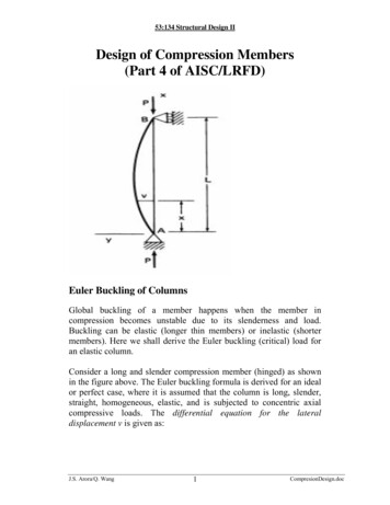
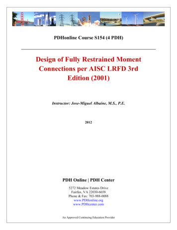
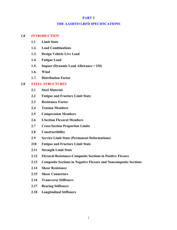
FEBRUARY 2019LRFD BRIDGE DESIGN5-10The weight of spiral reinforcement on a per foot basis is provided in Table5.2.2.3. The standard spiral reinforcement is 1/2 inch diameter with a3 inch pitch. When selecting the size of round columns, use outsidedimensions that are consistent with cover requirements and standard spiraloutside diameters.Figure 5.2.2.1 through 5.2.2.6 contain development length (Class A lap)and tension lap splice design tables for epoxy coated, plain uncoated, andstainless steel reinforcement bars. Knowing the bar size, location, concretecover, bar spacing, and class of splice, designers can readily find theappropriate lap length. The tables are based on 4 ksi concrete.Figure 5.2.2.7 contains development length tables for bars with standardhooks. Values are provided for epoxy coated, plain uncoated, and stainlesssteel reinforcement bars. Standard hook dimensions are also included.Figure 5.2.2.8 contains graphics that illustrate preferred and acceptablemethods for anchoring or lapping stirrup reinforcement. All stirrups mustbe anchored by hooking around longitudinal reinforcement. Detail closeddouble stirrups with a Class B lap. Also included in Figure 5.2.2.8 arestirrup and tie hook dimensions and a table showing minimum horizontalbar spacings for various concrete mixes.
FEBRUARY 2019LRFD BRIDGE DESIGN5-11Table 5.2.2.3Weight of Spiral ReinforcementWEIGHTS IN POUNDS PER FOOT OF HEIGHTO.D.SPIRAL3/8" DIA. ROD1/2" DIA. ROD6" PITCHF3" 6612.9919.546.1734.606813.3920.147.5735.70(in)For more complete coverage, see CRSI Manual of Standard Practice.Total weight (wt. per ft x height) FF weight to add for finishing(this includes 11/2 turns at the top and 11/2 turns at the bottom of spiral)For additional information see MnDOT 2472 and AASHTO LRFD 5.10.4.2
FEBRUARY 2019LRFD BRIDGE DESIGN5-12TENSION LAP SPLICES FOR EPOXY COATED BARS WITH 12” CONCRETE CAST BELOW(Applies only to epoxy coated bars with an angle to the horizontal of 0 to 45 degrees)fy 60 ksiConc. Bar4”Cover Size ClassClassAB3 1'-5" 1'-10"4 1'-11" 2'-6"5 2'-7" 3'-4"6 3'-1"4'-0"7 3'-11" 5'-1"2"8 5'-2"6'-8"9 6'-6" 8'-6"10 8'-3"10'-9"11 10'-2" 13'-3"14 N/AN/A3 1'-5" 1'-10"4 1'-11" 2'-6"5 2'-7" 3'-4"6 3'-1"4'-0"3"7 3'-11" 5'-1"28 5'-2"6'-8"89 6'-6" 8'-6"10 8'-3"10'-9"11 10'-2" 13'-3"14 N/AN/A3 1'-5" 1'-10"4 1'-11" 2'-6"5 2'-7" 3'-4"6 3'-1"4'-0"7 3'-11" 5'-1" 3”8 5'-2"6'-8"9 6'-6" 8'-6"10 8'-3"10'-9"11 10'-2" 13'-3"14 4'-0"4'-8"5'-4"6'-9"8'-7"10'-7"15'-3"5 1/2”ClassClassAB1'-5" 1'-10"1'-11" 2'-6"2'-5" 3'-1"3'-1"4'-0"3'-7" 4'-8"4'-1"5'-4"5'-1" 6'-7"6'-3"8'-2"7'-6" 9'-9"10'-8" 13'-10"1'-5" 1'-10"1'-11" 2'-6"2'-5" 3'-1"2'-10" 3'-8"3'-7" 4'-8"4'-1"5'-4"4'-9" 6'-2"6'-0"7'-10"7'-5" 9'-8"10'-8" 13'-10"1'-5" 1'-10"1'-11" 2'-6"2'-5" 3'-1"2'-10" 3'-8"3'-7" 4'-8"4'-1"5'-4"4'-9" 6'-2"6'-0"7'-10"7'-5" 9'-8"10'-8" 13'-10"fc’ 4 ksiReinforcement Bar Spacing6”6 1/2”ClassClassClassClassABAB1'-5" 1'-10" 1'-5" 1'-10"1'-11" 2'-6"1'-11" 2'-6"2'-5" 3'-1" 2'-5" 3'-1"3'-1"4'-0"3'-1"4'-0"3'-7" 4'-8" 3'-7" 4'-8"4'-1"5'-4"4'-1"5'-4"5'-1" 6'-7" 5'-1" 6'-7"6'-3"8'-2"6'-3"8'-2"7'-6" 9'-9" 7'-6" 9'-9"10'-4" 13'-5" 10'-4" 13'-5"1'-5" 1'-10" 1'-5" 1'-10"1'-11" 2'-6"1'-11" 2'-6"2'-5" 3'-1" 2'-5" 3'-1"2'-10" 3'-8"2'-10" 3'-8"3'-7" 4'-8" 3'-7" 4'-8"4'-1"5'-4"4'-1"5'-4"4'-8" 6'-0" 4'-8" 6'-0"5'-6"7'-2"5'-6"7'-2"6'-10" 8'-10" 6'-8" 8'-7"9'-9"12'-9" 9'-1"11'-10"1'-5" 1'-10" 1'-5" 1'-10"1'-11" 2'-6"1'-11" 2'-6"2'-5" 3'-1" 2'-5" 3'-1"2'-10" 3'-8"2'-10" 3'-8"3'-7" 4'-8" 3'-4" 4'-4"4'-1"5'-4"4'-1"5'-4"4'-8" 6'-0" 4'-8" 6'-0"5'-6"7'-2"5'-3"6'-9"6'-10" 8'-10" 6'-3" 8'-2"9'-9"12'-9" 3'-1"3'-8"4'-4"4'-11"6'-0"6'-9"7'-7"10'-11"7 1/2”ClassClassAB1'-5" 1'-10"1'-11" 2'-6"2'-5" 3'-1"3'-1"4'-0"3'-7" 4'-8"4'-1"5'-4"5'-1" 6'-7"6'-3"8'-2"7'-6" 9'-9"10'-4" 13'-5"1'-5" 1'-10"1'-11" 2'-6"2'-5" 3'-1"2'-10" 3'-8"3'-7" 4'-8"4'-1"5'-4"4'-8" 6'-0"5'-6"7'-2"6'-8" 8'-7"9'-1"11'-10"1'-5" 1'-10"1'-11" 2'-6"2'-5" 3'-1"2'-10" 3'-8"3'-4" 4'-4"3'-9"4'-11"4'-8" 6'-0"5'-3"6'-9"5'-10" 7'-6"7'-10" 10'-2" 8”ClassClass BA1'-5" 1'-10"1'-11" 2'-6"2'-5" 3'-1"3'-1"4'-0"3'-7" 4'-8"4'-1"5'-4"5'-1" 6'-7"6'-3"8'-2"7'-6" 9'-9"10'-4" 13'-5"1'-5" 1'-10"1'-11" 2'-6"2'-5" 3'-1"2'-10" 3'-8"3'-7" 4'-8"4'-1"5'-4"4'-8" 6'-0"5'-6"7'-2"6'-8" 8'-7"9'-1"11'-10"1'-5" 1'-10"1'-11" 2'-6"2'-5" 3'-1"2'-10" 3'-8"3'-4" 4'-4"3'-9"4'-11"4'-8" 6'-0"5'-3"6'-9"5'-10" 7'-6"7'-8"9'-11"Table is based on AASHTO Article 5.10.8.2.1a and includes modification factors for reinforcement location, epoxy coating, normalweight concrete, and reinforcement confinement as specified in AASHTO Articles 5.10.8.2.1b and 5.10.8.2.1c. Reinforcementconfinement is conservatively calculated by taking transverse reinforcement index as 0. Excess reinforcement factor is takenconservatively as 1.0. Tension lap splice lengths are based on AASHTO Article 5.10.8.4.3a. Concrete cover is defined as thecover to the bar being considered. For concrete cover or bar spacing that falls between table values, conservatively use lapsplice shown in the table for smaller concrete cover or bar spacing.TENSION LAP SPLICESWhere:Percent of As spliced within required lap lengthAs, provided/As, required 50 50 2Class AClass B 2Class BAs, provided Area of reinforcement providedandClass BAs, required Area of reinforcement required by analysisFigure 5.2.2.1Reinforcement Data
FEBRUARY 2019LRFD BRIDGE DESIGN5-13TENSION LAP SPLICES FOR EPOXY COATED BARS WITH 12” CONCRETE CAST BELOW(Applies to all other epoxy coated bars not covered by Figure 5.2.2.1)fy 60 ksiConc. BarCover Size1”𝟏1"22”23"8 '-7"4'-2"4'-9"6'-0"7'-7"9'-4"13'-5"5 1/2”ClassClassAB1'-5" 1'-10"1'-10" 2'-5"2'-9" 3'-6"3'-9"4'-10"4'-10" 6'-3"6'-0"7'-10"7'-4" 9'-7"8'-11" 11'-7"10'-6" 13'-8"14'-0" 18'-2"1'-1" 1'-5"1'-6"1'-11"2'-3" 3'-0"2'-9"3'-7"3'-7" 4'-8"4'-6"5'-11"5'-7" 7'-3"6'-10" 8'-11"8'-2" 10'-7"11'-0" 14'-4"1'-1" 1'-5"1'-6"1'-11"1'-10" 2'-5"2'-9"3'-7"3'-2" 4'-2"3'-8"4'-9"4'-6" 5'-10"5'-7"7'-2"6'-8" 8'-8"9'-5"12'-3"1'-1" 1'-5"1'-6"1'-11"1'-10" 2'-5"2'-2"2'-10"3'-2" 4'-2"3'-8"4'-9"4'-2" 5'-5"5'-4"6'-11"6'-7" 8'-6"9'-5"12'-3"1'-1" 1'-5"1'-6"1'-11"1'-10" 2'-5"2'-2"2'-10"3'-2" 4'-2"3'-8"4'-9"4'-2" 5'-5"5'-4"6'-11"6'-7" 8'-6"9'-5"12'-3"fc’ 4 ksiReinforcement Bar Spacing6”6 1/2”ClassClassClassClassABAB1'-5" 1'-10" 1'-5" 1'-10"1'-10" 2'-5"1'-10" 2'-5"2'-9" 3'-6" 2'-9" 3'-6"3'-9"4'-10" 3'-9"4'-10"4'-10" 6'-3" 4'-10" 6'-3"6'-0"7'-10" 6'-0"7'-10"7'-4" 9'-7" 7'-4" 9'-7"8'-11" 11'-7" 8'-11" 11'-7"10'-6" 13'-8" 10'-6" 13'-8"14'-0" 18'-2" 14'-0" 18'-2"1'-1" 1'-5" 1'-1" 1'-5"1'-6"1'-11" 1'-6"1'-11"2'-3" 3'-0" 2'-3" 3'-0"2'-9"3'-7"2'-9"3'-7"3'-7" 4'-8" 3'-7" 4'-8"4'-6"5'-11" 4'-6"5'-11"5'-7" 7'-3" 5'-7" 7'-3"6'-10" 8'-11" 6'-10" 8'-11"8'-2" 10'-7" 8'-2" 10'-7"11'-0" 14'-4" 11'-0" 14'-4"1'-1" 1'-5" 1'-1" 1'-5"1'-6"1'-11" 1'-6"1'-11"1'-10" 2'-5" 1'-10" 2'-5"2'-9"3'-7"2'-9"3'-7"3'-2" 4'-2" 3'-2" 4'-2"3'-8"4'-9"3'-8"4'-9"4'-6" 5'-10" 4'-6" 5'-10"5'-7"7'-2"5'-7"7'-2"6'-8" 8'-8" 6'-8" 8'-8"9'-1"11'-10" 9'-1"11'-10"1'-1" 1'-5" 1'-1" 1'-5"1'-6"1'-11" 1'-6"1'-11"1'-10" 2'-5" 1'-10" 2'-5"2'-2"2'-10" 2'-2"2'-10"3'-2" 4'-2" 3'-2" 4'-2"3'-8"4'-9"3'-8"4'-9"4'-1" 5'-4" 4'-1" 5'-4"4'-11" 6'-4"4'-10" 6'-4"6'-0" 7'-10" 5'-10" 7'-7"8'-8"11'-3" 8'-1"10'-5"1'-1" 1'-5" 1'-1" 1'-5"1'-6"1'-11" 1'-6"1'-11"1'-10" 2'-5" 1'-10" 2'-5"2'-2"2'-10" 2'-2"2'-10"3'-2" 4'-2" 2'-7" 3'-4"3'-8"4'-9"3'-8"4'-9"4'-1" 5'-4" 4'-1" 5'-4"4'-11" 6'-4"4'-7"6'-0"6'-0" 7'-10" 5'-7" 7'-2"8'-8"11'-3" 8'-0"10'-4"7”ClassClassAB1'-5" 1'-10"1'-10" 2'-5"2'-9" 3'-6"3'-9"4'-10"4'-10" 6'-3"6'-0"7'-10"7'-4" 9'-7"8'-11" 11'-7"10'-6" 13'-8"14'-0" 18'-2"1'-1" 1'-5"1'-6"1'-11"2'-3" 3'-0"2'-9"3'-7"3'-7" 4'-8"4'-6"5'-11"5'-7" 7'-3"6'-10" 8'-11"8'-2" 10'-7"11'-0" 14'-4"1'-1" 1'-5"1'-6"1'-11"1'-10" 2'-5"2'-9"3'-7"3'-2" 4'-2"3'-8"4'-9"4'-6" 5'-10"5'-7"7'-2"6'-8" 8'-8"9'-1"11'-10"1'-1" 1'-5"1'-6"1'-11"1'-10" 2'-5"2'-2"2'-10"3'-2" 4'-2"3'-8"4'-9"4'-1" 5'-4"4'-10" 6'-4"5'-10" 7'-7"8'-1"10'-5"1'-1" 1'-5"1'-6"1'-11"1'-10" 2'-5"2'-2"2'-10"2'-7" 3'-4"2'-11" 3'-9"4'-1" 5'-4"4'-7"6'-0"5'-2" 6'-8"7'-5"9'-7"7 1/2”ClassClassAB1'-5" 1'-10"1'-10" 2'-5"2'-9" 3'-6"3'-9"4'-10"4'-10" 6'-3"6'-0"7'-10"7'-4" 9'-7"8'-11" 11'-7"10'-6" 13'-8"14'-0" 18'-2"1'-1" 1'-5"1'-6"1'-11"2'-3" 3'-0"2'-9"3'-7"3'-7" 4'-8"4'-6"5'-11"5'-7" 7'-3"6'-10" 8'-11"8'-2" 10'-7"11'-0" 14'-4"1'-1" 1'-5"1'-6"1'-11"1'-10" 2'-5"2'-9"3'-7"3'-2" 4'-2"3'-8"4'-9"4'-6" 5'-10"5'-7"7'-2"6'-8" 8'-8"9'-1"11'-10"1'-1" 1'-5"1'-6"1'-11"1'-10" 2'-5"2'-2"2'-10"3'-2" 4'-2"3'-8"4'-9"4'-1" 5'-4"4'-10" 6'-4"5'-10" 7'-7"8'-1"10'-5"1'-1" 1'-5"1'-6"1'-11"1'-10" 2'-5"2'-2"2'-10"2'-7" 3'-4"2'-11" 3'-9"4'-1" 5'-4"4'-7"6'-0"5'-1" 6'-8"6'-11" 9'-0" able is based on AASHTO Article 5.10.8.2.1a and includes modification factors for reinforcement location, epoxy coating, normalweight concrete, and reinforcement confinement as specified in AASHTO Articles 5.10.8.2.1b and 5.10.8.2.1c. Reinforcementconfinement is conservatively calculated by taking transverse reinforcement index as 0. Excess reinforcement factor is takenconservatively as 1.0. Tension lap splice lengths are based on AASHTO Article 5.10.8.4.3a. Concrete cover is defined as thecover to the bar being considered. For concrete cover or bar spacing that falls between table values, conservatively use lapsplice shown in the table for smaller concrete cover or bar spacing.TENSION LAP SPLICESPercent of As spliced within required lap lengthAs, provided/As, requiredWhere: 50 50 2Class AClass B 2Class BClass BAs, provided Area of reinforcement providedandAs, required Area of reinforcement required by analysisFigure 5.2.2.2Reinforcement Data
FEBRUARY 2019LRFD BRIDGE DESIGN5-14TENSION LAP SPLICES FOR PLAIN UNCOATED BARS WITH 12” CONCRETE CAST BELOW(Applies only to plain uncoated bars with an angle to the horizontal of 0 to 45 degrees)fy 60 ksiConc. BarCover Size2” 5 1/2”ClassClassClassClassABAB1'-3" 1'-7" 1'-3" 1'-7"1'-7"2'-1"1'-7"2'-1"2'-0" 2'-7" 2'-0" 2'-7"2'-5"3'-1"2'-5"3'-1"2'-9" 3'-7" 2'-9" 3'-7"3'-2"4'-1"3'-2"4'-1"4'-0" 5'-2" 3'-11" 5'-1"5'-1"6'-7"4'-10" 6'-3"6'-3" 8'-1" 5'-9" 7'-6"9'-0"11'-8" 8'-2"10'-7"1'-3" 1'-7" 1'-3" 1'-7"1'-7"2'-1"1'-7"2'-1"2'-0" 2'-7" 2'-0" 2'-7"2'-5"3'-1"2'-5"3'-1"2'-9" 3'-7" 2'-9" 3'-7"3'-2"4'-1"3'-2"4'-1"4'-0" 5'-2" 3'-8" 4'-9"5'-1"6'-7"4'-7"6'-0"6'-3" 8'-1" 5'-8" 7'-4"9'-0"11'-8" 8'-2"10'-7"fc’ 4 ksiReinforcement Spacing6”6 1/2”ClassClassClassClassABAB1'-3" 1'-7" 1'-3" 1'-7"1'-7"2'-1"1'-7"2'-1"2'-0" 2'-7" 2'-0" 2'-7"2'-5"3'-1"2'-5"3'-1"2'-9" 3'-7" 2'-9" 3'-7"3'-2"4'-1"3'-2"4'-1"3'-11" 5'-1" 3'-11" 5'-1"4'-10" 6'-3"4'-10" 6'-3"5'-9" 7'-6" 5'-9" 7'-6"7'-11" 10'-3" 7'-11" 10'-3"1'-3" 1'-7" 1'-3" 1'-7"1'-7"2'-1"1'-7"2'-1"2'-0" 2'-7" 2'-0" 2'-7"2'-5"3'-1"2'-5"3'-1"2'-9" 3'-7" 2'-9" 3'-7"3'-2"4'-1"3'-2"4'-1"3'-7" 4'-7" 3'-7" 4'-7"4'-3"5'-6"4'-0"5'-2"5'-3" 6'-9" 4'-10" 6'-3"7'-6"9'-9"6'-11" 9'-0"7”ClassClassAB1'-3" 1'-7"1'-7"2'-1"2'-0" 2'-7"2'-5"3'-1"2'-9" 3'-7"3'-2"4'-1"3'-11" 5'-1"4'-10" 6'-3"5'-9" 7'-6"7'-11" 10'-3"1'-3" 1'-7"1'-7"2'-1"2'-0" 2'-7"2'-5"3'-1"2'-9" 3'-7"3'-2"4'-1"3'-7" 4'-7"4'-0"5'-2"4'-6" 5'-10"6'-5"8'-4"7 1/2”ClassClassAB1'-3" 1'-7"1'-7"2'-1"2'-0" 2'-7"2'-5"3'-1"2'-9" 3'-7"3'-2"4'-1"3'-11" 5'-1"4'-10" 6'-3"5'-9" 7'-6"7'-11" 10'-3"1'-3" 1'-7"1'-7"2'-1"2'-0" 2'-7"2'-5"3'-1"2'-9" 3'-7"3'-2"4'-1"3'-7" 4'-7"4'-0"5'-2"4'-5" 5'-9"6'-0"7'-10" "4'-7"5'-2"5'-9"7'-7"Table is based on AASHTO Article 5.10.8.2.1a and includes modification factors for reinforcement location, epoxy coating, normalweight concrete, and reinforcement confinement as specified in AASHTO Articles 5.10.8.2.1b and 5.10.8.2.1c. Reinforcementconfinement is conservatively calculated by taking transverse reinforcement index as 0. Excess reinforcement factor is takenconservatively as 1.0. Tension lap splice lengths are
FEBRUARY 2019 LRFD BRIDGE DESIGN 5-6 5.2 Reinforcement Details 5.2.1 Minimum Clear Cover and Clear Spacing Practices for detailing a variety of reinforced concrete elements are presented in this section. These include standard concrete cover and bar spacing dimensions, plus a variety of specific design and detailing instructions.File Size: 1009KB