Transcription
Electrical
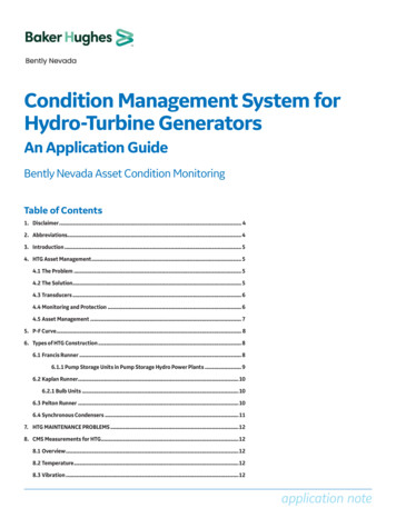
Science and Reactor Fundamentals – ElectricalCNSC Technical Training GroupiTable of Contents1 Objectives. 11.11.21.31.4BASIC ELECTRICAL THEORY. 1TRANSFORMERS . 1GENERATORS. 2PROTECTION . 32 BASIC ELECTRICAL THEORY. 42.1 INTRODUCTION . 42.2 ELECTRICAL TERMS . 102.2.112.2.122.2.13Current (I, Amps) . 4Potential (V, Volts). 4Resistance (R, Ohms) . 4Capacitance (C, Farads). 5Magnetic Flux (Unit of Measurement isWebers) . 5Inductance (L, Henrys). 6Frequency (f, Hertz) . 6Reactance (X, Ohms). 6Impedance (Z, Ohms) . 7Active Power (P Watts) . 7Reactive Power (Q, Vars) . 7Apparent Power (U, Volt Amps) . 8Power Factor (PF). 82.3 RELATIONSHIPS OF THE BASICELECTRICAL QUANTITIES. 82.3.12.3.22.3.32.3.42.3.52.3.6Voltage vs. Current in a Resistor, Capacitoror Inductor . 8dc Circuit Components. 9Resistors . 9Capacitors . 10Inductors . 11Transient Effects. 122.4 PHASORS . 122.5 AC CIRCUIT COMPONENTS . 132.5.12.5.22.5.32.5.42.5.52.5.6Revision 1 – March 2003Resistors . 13Inductors . 14Capacitors . 15Circuits with multiple components. 16Acrostic . 18Heat vs. Current in a Resistor. 18NotesNotes:
Science and Reactor Fundamentals – ElectricalCNSC Technical Training GroupNotesii2.6 ACTIVE, REACTIVE, APPARENT POWERAND POWER FACTOR . 202.6.12.6.22.6.32.6.4Active or Real Power (Measured in Watts orW) . 20Reactive Power (Measured in Volt AmpReactive or VAR’s). 20Apparent Power (Measured in Volt Amps orVA). 21Apparent Power . 222.7 MAGNETIC FIELD PRODUCED BY ACURRENT FLOWING IN A CONDUCTOR. 242.8 INDUCED VOLTAGE PRODUCED BY ACHANGING MAGNETIC FIELD IN ACONDUCTOR . 252.8.12.8.22.8.3Transformer Action . 27Magnetic Force on a Current CarryingConductor. 27Induced Voltage in a Conductor . 292.9 THREE PHASE CONNECTIONS . 342.10 MAGNETIC CIRCUITS . 352.10.12.10.22.10.3Eddy Currents . 35Hysteresis . 36Magnetic Saturation. 362.11 POWER CONVERTERS . 382.12 MACHINE INSULATION . 392.12.12.12.2Excessive Moisture. 39Excessive Temperature. 402.13 REVIEW QUESTIONS - BASIC ELECTRICALTHEORY 413 Transformers . 433.1 INTRODUCTION . 433.2 TRANSFORMERS - GENERAL . 433.2.13.2.23.2.33.2.43.2.53.2.63.2.73.2.8VA Rating . 43Cooling. 43Frequency. 44Voltage . 45Phase . 45Windings. 45Connections. 46Taps . 473.3 TAP-CHANGERS . 47Revision 1 – March 2003
Science and Reactor Fundamentals – ElectricalCNSC Technical Training Group3.3.13.3.2iiiOff-Load Tap Changers . 48On-Load Tap Changers. 493.4 OPERATING LIMITATIONS. 533.4.13.4.23.4.33.4.43.4.53.4.6Transformer Losses (Heat) . 53Copper (or Winding) Losses . 53Iron (or Core) Losses . 54Transformer Temperature Limitations. 55Current Limits . 56Voltage and Frequency Limits . 563.5 INSTRUMENT TRANSFORMERS. 573.5.13.5.2Potential Transformers . 57Current Transformers . 57REVIEW QUESTIONS - TRANSFORMERS . 594 GENERATORS. 604.1 INTRODUCTION . 604.2 FUNDAMENTALS OF GENERATOROPERATION . 604.3 SYNCHRONOUS OPERATION . 614.3.14.3.24.3.34.3.44.3.5The Magnetic Fields. 61Forces between the Magnetic Fields. 63Motoring. 64Limits. 65Synchronized Generator Equivalent Circuit654.4 STEADY SATE PHASOR DIAGRAM . 664.4.14.4.2Increasing steam flow . 67Increasing Excitation . 674.5 GENERATOR RUN-UP TOSYNCHRONIZATION. 684.5.14.5.2Runup . 68Applying Rotor Field. 694.6 PREPARING TO SYNCHRONIZE . 704.6.14.6.24.6.34.6.4Phase Sequence. 71Voltage Magnitude . 71Frequency. 72Phase Angle. 734.7 SYNCHRONIZING . 734.8 GENERATOR SYNCHRONIZATION. 754.8.14.8.24.8.34.8.4Armature Reaction . 76Active Component . 76Reactive Lagging Component . 76Reactive Leading Component . 774.9 CLOSING ONTO A DEAD BUS. 77Revision 1 – March 2003NotesNotes:
Science and Reactor Fundamentals – ElectricalCNSC Technical Training GroupNotes4.9.14.9.24.9.34.9.4ivClosing onto a Dead Bus with Leading PFLoad. 77Closing onto a Dead Bus with Lagging PFLoad. 77Closing onto a Faulted Bus. 77Closing onto a Dead Bus with no ConnectedLoads . 784.10 GENERATOR LOADING. 784.10.1Closing onto a Finite vs Infinite System. 784.11 GENERATOR AVR CONTROL. 784.11.14.11.24.11.3AVR Action to Generator Loading. 80Unity PF Load. 81Zero PF Lagging Load. 824.12 GENERATOR GOVERNOR CONTROL. 844.12.14.12.24.12.34.12.44.12.54.12.64.12.7Droop . 85Isochronous . 85Percentage Speed Droop. 86During Runup. 87Normal Operation . 88Parallel Operation on a Large (Infinite) Bus88Parallel Operation on a Finite Bus. 904.13 COMBINED AVR/GOVERNOR CONTROL . 924.13.14.13.2Adjusting Steam Flow without ChangingExcitation . 92Adjusting Excitation without Changing theSteam Flow. 934.14 GENERATOR STABILITY . 944.15 GENERATOR OUT OF STEP . 954.16 GENERATOR HEAT PRODUCTION ANDADVERSE CONDITIONS . 974.16.14.16.24.16.34.16.4Rotor Heating Limitations. 98Stator Heating Limitations. 99generator heating limits . 99Generator Rotor and Stator Cooling . 1014.17 GENERATOR SHUTDOWN . 1044.18 REVIEW QUESTIONS GENERATOR . 1055 Electrical Protection. 1075.1 INTRODUCTION . 1075.2 PURPOSE OF ELECTRICAL PROTECTION . 1075.3 ESSENTIAL QUALITIES OF ELECTRICALPROTECTIONS . 108Revision 1 – March 2003
Science and Reactor Fundamentals – ElectricalCNSC Technical Training Group5.3.15.3.25.3.35.3.4vSpeed . 108Reliability . 109Security. 109Sensitivity . 1095.4 PROTECTION ZONES . 1095.5 BREAKER FAILURE PROTECTION. 1125.5.1Duplicate A and B Protections. 1135.6 BUS PROTECTIONS . 1145.6.15.6.25.6.35.6.4Bus Differential Protection . 115Bus Over-Current Backup. 117Bus Ground Faults . 119Bus Under-Voltage Protection. 1195.7 TRANSFORMER PROTECTION. 1205.7.15.7.25.7.35.7.45.7.55.7.6Transformer Instantaneous Over-CurrentProtection. 121Transformer Differential Protection . 121Transformer Gas Relay . 123Generation of Gas Due to Faults . 124Transformer Thermal Overload. 125Transformer Ground Fault Protection. 1275.8 MOTOR PROTECTION. 1285.8.15.8.25.8.35.8.45.8.55.8.6Motor Instantaneous Over-current Protection128Motor Timed Over-Current Protection. 128Thermal OverLoad . 130Motor Ground Fault Protection. 131Motor Stall Protection. 132Motor Over-Fluxing Protection . 1345.9 GENERATOR PROTECTION . 9.105.9.11Classes of Turbine Generator Trips. 136Generator Over-Current . 137Generator Differential Protection. 137Generator Ground Fault Protection . 139Rotor Ground Fault Protection. 140Generator Phase Unbalance Protection. 141Generator Loss of Field Protection . 142Generator Over-Excitation Protection . 142Generator Under-frequency Protection. 143Generator Out of Step Protection . 143Generator Reverse Power Protection . 1445.10 REVIEW QUESTIONS-ELECTRICALPROTECTION . 145Revision 1 – March 2003NotesNotes:
Science and Reactor Fundamentals – ElectricalCNSC Technical Training Group1MODULE 5INTRODUCTIONThis module covers the following areas pertaining to electrical: Basic electrical theory Transformers Generators ProtectionAt the completion of the module the participant will be able to:1OBJECTIVES1.1BASIC ELECTRICAL THEORY explain the following electrical terms: current, potential,resistance, capacitance, magnetic flux, inductance, frequency,reactance, impedance, active power, reactive power, apparentpower, power factor; identify the unit of measurement of electrical quantities; explain relationship between electrical quantities; describe how excessive moisture and temperature can affect theinsulation; resistance of materials used in electrical machines;1.2TRANSFORMERS explain how tap changers are used to change the ratio of inputto output voltage; explain the operational limitation of off-load tap changers; identify the factors that cause heating in transformers; explain the operating conditions that affect heat production; identify the limitations on transformer operation.Revision 1 – March 2003NotesNotes:
Science and Reactor Fundamentals – ElectricalCNSC Technical Training GroupNotes1.32GENERATORS explain why excitation is only applied when a generator is at ornear rated speed; explain why the electrical parameters parameters must bewithin acceptable limits before a generator can be connected toan electrical system; identify how synchroscope indication is interpreted to ensurecorrect conditions exist to close the breaker; explain how a generator responds when the breaker is closedonto a dead bus with capacitive or inductive loads attached; identify why electrical loads should be disconnected prior toenergizing a bus; define finite and infinite bus describe how generator terminal voltage is automaticallycontrolled describe the function of a turbine governor; describe how generator parameters are affected by changes ineither turbine shaft power or excitation current when agenerator is connected to an infinite grid; describe the factors that influence steady state limit andtransient stability in generators and transmission lines; explain why limits are placed on generator parameters; describe the changes that occur during a load rejection fromload power; describe the speed and voltage control systems response duringa load rejection from full power; explain why heat is produced in generator components and theconsequence of excessive heat production; identify how heat is removed from the rotor and stator; explain why stator water conductivity is limited;Revision 1 – March 2003
Science and Reactor Fundamentals – ElectricalCNSC Technical Training Group state the consequences of exceeding the conductivity limit; explain how the ingress of water or air into the generatorimpairs the ability of the hydrogen to insulate and cool thegenerator.1.43PROTECTION explain how differential protection is used to provideprotection to a bus; identify why differential, over-current back-up, ground faultand under voltage are required to provide protection forelectrical busses; identify why instantaneous over-current, differential, gas relay,thermal overload and ground fault are required to provideprotection for electrical transformers; explain why instantaneous over-current, timed over-current,thermal overload, ground fault, stall and over-fluxing arerequired to provide protection for electrical motors; identify why it is acceptable to immediately reset a thermaloverload relay on an electrical motor and not an instantaneousover-current relay; identify when a class A, B, C, or D turbine trip can occur; explain why over-current, differential, ground fault, phaseimbalance, loss of field, over-excitation, under-frequency,pole-slip, reverse power and rotor ground fault are required toprovide protection for electrical generators.Revision 1 – March 2003NotesNotes:
Science and Reactor Fundamentals – ElectricalCNSC Technical Training GroupNotes2BASIC ELECTRICAL THEORY2.1INTRODUCTION4The first section examines the definitions and interrelations of thebasic electrical quantities (Amps, Volts, Watts, Vars, Power Factor,etc.). It will also investigate basic ac/dc electrical theory that formsthe basis of operation of electrical equipment (motors, transformers,generators, power converters and un-interruptible power supplies)2.2ELECTRICAL TERMSWhat is commonly defined as electricity is really just the movement ofelectrons. So, let’s start at that point.2.2.1 Current (I, Amps)Current (as the name implies) is the movement or flow of electrons (I)and is measured in units of Amperes. This is usually abbreviated toAmp or, even shorter, A. The flow of electrons in an electrical currentcan be considered the same as the flow of water molecules in a stream.To get anything to move requires potential and the same thing happensto electrons.2.2.2 Potential (V, Volts)Potential is the force (called Electromotive Force or EMF) that drivesthe electrons and has a measurement of voltage. This is abbreviated asa unit of measurement to Volt or even further to V.2.2.3 Resistance (R, Ohms)Resistance is the property that resists current flow. It is analogous tofriction in mechanical systems. The unit of this is ohm (we have togive some credit to the fellow who first named it). It is sometimesshown with its official ohm mark (Ω) and the short form of the wordresistance is always R. Resistance not only depends on the materialused for the conductor but also upon size and temperature.Increase in the cross-sectional area will decrease the resistanceIncrease in the length will increase the resistance Increase in the temperature will increase theresistance (for most materials that conductelectricity)Revision 1 – March 2003
Science and Reactor Fundamentals – ElectricalCNSC Technical Training Group52.2.4 Capacitance (C, Farads)Any two conductors separated by an insulating material form acapacitor or condenser. Capacitance of a device is its capacity to holdelectrons or a charge. The units of measurement are farads. Wecommonly see it in smaller amounts called microfarads µF and picofarads pF. Capacitance depends on the construction.Figure 1Capacitance The closer the plates are together the larger the capacitance The larger the area of the plates the larger the capacitance2.2.5 Magnetic Flux (Unit of Measurement is Webers)When current flows in a conductor, a magnetic field is created aroundthat conductor. This field is commonly presented as lines of magneticforce and magnetic flux refers to the term of measurement of themagnetic flow within the field. This is comparable to the term currentand electron flow in an electric field. The following illustration showsthe direction of magnetic flux around a conductor and the applicationof the easily remembered right-hand-rule.Mentally, place your right hand around the conductor with the thumbpointing in the direction of current flow and the fingers will curl in thedirection of magnetic flux.Revision 1 – March 2003NotesNotes:
Science and Reactor Fundamentals – ElectricalCNSC Technical Training GroupNotes6Figure 2Magnetic Lines of Force (MMF)Lines of magnetic force (MMF) have an effect on adjacent conductorsand even itself.This effect is most pronounced if the conductoroverlaps itself as in the shape of a coil.Figure 3Magnetic Self-InductanceAny current-carrying conductor that is coiled in this fashion forms anInductor, named by the way it induces current flow in itself (selfinductance) or in other conductors.2.2.6 Inductance (L, Henrys)Opposition to current flowing through an inductor is inductance. Thisis a circuit property just as resistance is for a resistor. The inductanceis in opposition to any change in the current flow. The unit ofinductance is Henry (H) and the symbol is L.2.2.7 Frequency (f, Hertz)Any electrical system can be placed in one of two categories directcurrent (dc) or alternating current (dc). In dc systems the current onlyflows in one direction. The source of energy maintains a constantelectromotive force, as typical with a battery. The majority ofelectrical systems are ac.Frequency is the rate of alternating the direction of current flow. Theshort form is f and units are cycles per second or Hertz (short-formedto Hz).2.2.8 Reactance (X, Ohms)The opposition to alternating current (ac) flow in capacitors andinductors is known as reactance. The symbol for capacitive reactanceis XC and for inductive reactance XL.Revision 1 – March 2003
Science and Reactor Fundamentals – ElectricalCNSC Technical Training Group7Although we will not go into the derivation of the values, it can beshown that when f is the frequency of the ac current:XL 2 Πf LXC 1/2ΠfC2.2.9 Impedance (Z, Ohms)The total opposition or combined impeding effect of resistance plusreactance to the flow of alternating current is impedance. The wordimpedance is short formed to Z and the unit is ohms. The relationshipcan be illustrated in a simple series circuit shown below:AC Current (I)RResistanceXLXCReactanceImpedanceFigure 4Impedance2.2.10 Active Power (P Watts)Instead of working directly with the term electrical energy, it is normalpractice to use the rate at which energy is utilized during a certain timeperiod. This is defined as power. There are three components ofpower: active, reactive and apparent.Active power or real power is the rate at which energy is consumedresulting in useful work being done. For example, when current flowsthrough a resistance, heat is given off.It is given the symbol P and has the units of Watts.2.2.11 Reactive Power (Q, Vars)Reactive power is the power produced by current flowing throughreactive elements, whether inductance or capacitance. It is given therepresentative letter Q and has the units volt-amp-reactive (VAR).Reactive power can also be considered as the rate of exchange ofenergy between a capacitor or inductor load and a generator orbetween capacitors and inductors.Revision 1 – March 2003NotesNotes:
Science and Reactor Fundamentals – ElectricalCNSC Technical Training GroupNotes8Although it does not produce any real work, it is the necessary forceacting in generators, motors and transformers. Examples of this arethe charging/discharging of a capacitor or coil. Although this creates atransfer of energy, it does not consume or use power as a resistorwould.2.2.12 Apparent Power (U, Volt Amps)Apparent power is the total or combined power produced by currentflowing through any combination of passive and reactive elements. Itis given the representative letter U and has the units volt-amps (VA).2.2.13 Power Factor (PF)Real power/ apparent powerPower Factor is the comparison of Real power to apparent power. For a resistor, there is no reactive power consumed. Thusapparent power used is totally real. The power factor would be1 or often referred to as unity power factor For a pure inductor or capacitor, the apparent power consumedis entirely reactive (real power is nil). The power factor wouldthen be 0. For power consumed by an impedance consisting of resistance,inductance and capacitance the power factor will of coursevary between these two limits.The most efficient use or consumption of power is obtained as weapproach unity power factor2.3RELATIONSHIPS OF THE BASICELECTRICAL QUANTITIES2.3.1Voltage vs. Current in a Resistor, Capacitor or InductorElements in an electrical system behave differently if they areexposed to direct current as compared to alternating current. Forease of explanation, the devices have often been compared to similarevery day items. Resistors in electrical systems are similar to rocks in a streamof water. A capacitor is comparable to a boat paddle inserted into thestream. The action of inductor is similar to a coiled spring.Revision 1 – March 2003
Science and Reactor Fundamentals – ElectricalCNSC Technical Training Group2.3.29NotesNotes:dc Circuit ComponentsLet us first look at the simple case of a dc circuitcomposed of a constant EMF (battery) and the threebasic elements and two configurations(series/parallel).2.3.3 ResistorsAs the current flows through the resistors, in the same way that waterflows over rocks, it expends some of its energy. If the rocks in astream were in the form of rapids, the stream would have considerableresistance. However, if the same amount of rocks were placed in arow across the stream, the overall resistance to current flow would beless.The diagrams below illustrate the basic but underlying principle in themajority of electrical systems. The amount of potential required toforce 1 Amp through 1 Ohm of resistance is 1 Volt (Ohms Law). Thisis often written as V IR.In the series circuit (on left), the same current flows through everyresistor, but the applied voltage is divided between them. In theparallel circuit (on right), the same voltage is applied to all resistorsbut the current divides between them.Current (I)Current (I)R PotentialSource(V) -RRSeriesCircuitRR PotentialSource(V)RWith all 6 Resistances the same value (R)Current would be 6 times lessthat of 1 resistance (R)RRRRRRParallel CircuitWith all 6 Resistances the same value (R)Current would be 6 times morethat of 1 resistance (R)Figure 5dc Circuit ResistanceFor a series circuit the total resistance is stated as RTotal R1 R2 (etc.).In this example RTotal 6R.Revision 1 – March 2003
Science and Reactor Fundamentals – ElectricalCNSC Technical Training GroupNotes10 For a parallel circuit the total resistance is stated as 1/RTotal 1/R1 1/R2 (etc.). In this example 1/RTotal 6/Ror RTotal R/6. Circuits containing a combination of series and parallelportions apply the same basic theory with more lengthycalculations.2.3.4 CapacitorsA capacitor, as previously described, is physically made of twoconducting surfaces separated by an insulator. In an electrical circuitcapacitors have both a steady state and transient effect on the circuit.As the electrical conductors are not in physical contact, it will not, inthe long-term pass direct current. The action is the same as placing aboat paddle against a stream of water - it blocks current flow. Howeverwhen voltage is first applied to a capacitor current will flow until thecapacitor is charged. This is a transient effect.Current (I) 0 PotentialSource(V)C-Capacitors will not pass DC CurrentFigure 6dc Circuit Capacitance Steady State EffectRevision 1 – March 2003
Science and Reactor Fundamentals – ElectricalCNSC Technical Training acitorChargingVCICTimeFigure 7dc Circuit Capacitance Transient Effect2.3.5 InductorsThe inductor as illustrated in Figure 8 is similar to a coiled spring andin the steady, has no resisting capability. If a steady force is exertedon it, it can pass huge amounts of energy limited only by the supplycapability or heaviness of the inductor. An inductor in a dc system hasto be used with caution as it allows unrestricted flow of energy andwill drain the energy source or damage the inductor itself. However,when voltage is first applied the inductor impedes current flow in thecircuit.Current (I) unlimited PotentialSource(V) -LInductors are a Short circuit to DC CurrentFigure 8dc Circuit Inductance Steady State EffectRevision 1 – March 2003
Science and Reactor Fundamentals – ElectricalCNSC Technical Training Group12NotesILVLorILVLTimeFigure 9dc Circuit Inductor Transient Effect2.3.6 Transient EffectsThe transient effects of capacitors and inductors are the result of storedenergy in the electrical circuit. Energy is stored in two forms, as storedelectrical charge in a capacitor and in the magnetic field in an inductor.The amount of energy stored in an inductor depends on the current inthe circuit; the amount of energy in a capacitor depends on the voltageacross it. If the circuit conditions change so will the amount of energystored in the component and a transient will occur.One way of looking at the transient effects of these components is thatinductors resist changes in current flow in a circuit and capacitorsresist changes in voltage. In basic dc circuits inductors and capacitorsare for the most part curiosities. However, in an ac circuit the voltageand current are continuously changing so capacitor and inductors havea continuous effect on the circuit.2.4PHASORSThe voltages and currents in ac circuits are continuously changing insinusoidal patterns. In ac theory not only are we concerned with themagnitude of the voltage and current sine curves but also, the phase(the angle between the peaks) of them. There are numerousmathematical methods of representing these sine curves; one of themost common in electrical work is the phasor diagram.Revision 1 – March 2003
Science and Reactor Fundamentals – ElectricalCNSC Technical Training Group13NotesNotes:V1V1Figure 10Sine curve and PhasorA phasor looks a lot like a vector however it is not. A vector representsa magnitude and direction; a phasor represents a magnitude and anangle. Although, when it comes to manipulating phasor (adding orsubtracting) quantities, all of the rules of vector addition andsubtraction apply. Representing a single sine curve with a phasor is alittle silly but when we go to compare sine curves then phasors are ahandy tool.V2V2V1θθV1Figure 11Phasor representation of two voltagesFigure 11 shows the phasor representation of two voltages that are notin phase nor equal in magnitude. In this diag
explain why instantaneous over-current, timed over-current, thermal overload, ground fault, stall and over-fluxing