Transcription
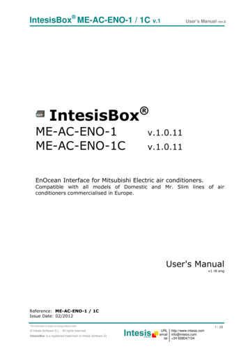
IntesisBox DK-AC-ENO-1 / 1C v.1IntesisBoxDK-AC-ENO-1DK-AC-ENO-1CUser’s Manual rev.6 v.1.0.12v.1.0.12EnOcean Interface for Daikin air conditioners.Compatible with Domestic linesUser's Manualv1 r6 engReference: DK-AC-ENO-1 / 1CIssue Date: 02/2012 Intesis Software S.L. - All rights reservedThis information is subject to change without noticeIntesisBox is a registered trademark of Intesis Software m 34 9380471341 / 30
IntesisBox DK-AC-ENO-1 / 1C v.1 Intesis Software S.L.User’s Manual rev.6All Rights Reserved.Information in this document is subject to change without notice. The software described inthis document is furnished under a license agreement or nondisclosure agreement. Thesoftware may be used only in accordance with the terms of those agreements. No part ofthis publication may be reproduced, stored in a retrieval system or transmitted in any formor any means electronic or mechanical, including photocopying and recording for anypurpose other than the purchaser’s personal use without the written permission of IntesisSoftware S.L.Intesis Software S.L.Milà I Fontanals, 1 bis, 1º08700 IgualadaSpainTRADEMARKSAll trademarks and tradenames used in this document are acknowledged to be the copyright of their respective holders Intesis Software S.L. - All rights reservedThis information is subject to change without noticeIntesisBox is a registered trademark of Intesis Software m 34 9380471342 / 30
IntesisBox DK-AC-ENO-1 / 1C v.1User’s Manual rev.6INDICE1.Presentation . 41.1. Main Features: . 41.2. Typical Application. 52.Connection and placement . 72.1. Connection . 72.2. Placement . 82.2.1Screening zones . 82.2.2Penetration Angle . 92.2.3Distance between Receiver and sources of interference . 92.2.4Use of repeaters . 93.Configuration . 103.1. Learning procedure . 113.2. Teach-in procedure . 133.3. Device deleting procedure . 144.Special Behaviors . 154.1. Window contact . 154.2. External temperature Sensors. Virtual temperature . 154.3. Key Card . 164.4. Occupancy sensors . 164.5. MultiTeach-in procedure . 175.Communications monitoring. 185.1. AC communication monitoring mode (RED LED) . 185.2. EnOcean communication monitoring mode (GREEN LED) . 186.Technical data and dimensions . 197.A.C profile data (Generic HVAC interface) . 208.AC Unit Types compatibility . 259.Error Codes . 2610.EnOcean Interoperability . 2911.Regulations and standards . 30 Intesis Software S.L. - All rights reservedThis information is subject to change without noticeIntesisBox is a registered trademark of Intesis Software m 34 9380471343 / 30
IntesisBox DK-AC-ENO-1 / 1C v.1User’s Manual rev.61. PresentationDK-AC-ENO-1 and DK-AC-ENO-1C devices allow a complete andnatural integration of Daikin air conditioners with EnOceancontrol systems both in their 868 MHz (DK-AC-ENO-1) and 315MHz (DK-AC-ENO-1C) versions.Compatible with the domestic AC units commercialized by Daikin(check section 8)1.1. Main Features: Reduced dimensions. Quick installation. External power not required. Direct connection to the Daikin AC indoor unit. Fully EnOcean interoperable. Multiple profiles Control of the AC unit based in the ambient temperature read by the own AC unit, orin the ambient temperature read by any EnOcean thermostat. Total Control and Monitoring of the AC unit from EnOcean, including monitoring of ACunit’s state of internal variables, and error indication and error code. AC unit can be controlled simultaneously by the IR remote control of the AC unit andby EnOcean devices. Implements the newly approved HVAC EEP’s Advanced room control functionalities. Configurable to work as a repeater. Intesis Software S.L. - All rights reservedThis information is subject to change without noticeIntesisBox is a registered trademark of Intesis Software m 34 9380471344 / 30
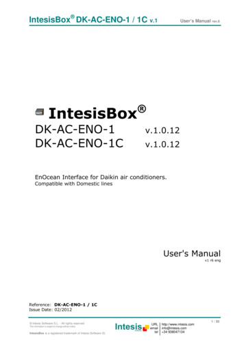
IntesisBox DK-AC-ENO-1 / 1C v.1User’s Manual rev.61.2. Typical ApplicationIn Figure 1.1 it is shown a typical application of DK-AC-ENO-1 / 1C in a hotel room. Thedifferent devices that control the AC unit, like switches, Key cards, window contacts, areconnected to it through the DK-AC-ENO-1 / 1C. EnOcean standardcommunication Small Dimensions Fast Installation No external PS Several Profiles Direct connection toAC unitDK-AC-ENO-1/1CDK-AC-ENO-1/1CFigure 1.1 Typical application of DK-AC-ENO-1 / 1C in a hotel Intesis Software S.L. - All rights reservedThis information is subject to change without noticeIntesisBox is a registered trademark of Intesis Software m 34 9380471345 / 30
IntesisBox DK-AC-ENO-1 / 1C v.1User’s Manual rev.6A schematic view of what it could be the application shown in Figure 1.1 can be seen inFigure 1.2. The connection diagram of the A.C with the DK-AC-ENO-1 / 1C and some of thesupported EnOcean devices are shown53 mmCable de conexiónsuministrado con elinterfaz.40 mm IntesisBoxDK-AC-ENOTypical transmitting EnOceandevices: Thermostat Switches Key Cards Window contact Occupancy sensorsTypical receiving EnOcean devices: Actuators Gateway.Figure 1.2 Example of DK-AC-ENO-1 / 1C control or actuation devices Intesis Software S.L. - All rights reservedThis information is subject to change without noticeIntesisBox is a registered trademark of Intesis Software m 34 9380471346 / 30
IntesisBox DK-AC-ENO-1 / 1C v.1User’s Manual rev.62. Connection and placement2.1. ConnectionDisconnect mains power from the AC unit. Open the front cover of the indoor unit in orderto have access to the internal control board. In the control board locate the socketconnector marked as:S21in Domestic line modelsUsing the cable that comes with the interface, insert one of its connectors, the biggest one,into the socket of the DK-AC-ENO-1 / 1C, and the other connector, the one installed in thelargest uncovered part, to the socket S21 of the AC unit's electronic circuit. Close the ACindoor unit's front cover again.AC indoor unitElectroniccircuit boardInsert the cable throughthe hole and Follow theinstructions belowS21200 mmConnection cablesupplied with theinterface.40 mm IntesisBoxDK-AC-ENO-1 / 1CFigure 2.1 Device connection diagramImportant: Extending or shortening the length of connection cable included with theinterface may cause it to malfunction.To connect the device to the AC, the recommended methods are the ones in Figure 2.2 Method1: The lid hole is place above CON1 (Figure 2.2 or Figure 3.1)Method2: The lid hole is placed on the opposite side. Use the supplied staple to fix thecable to the screw used for wall fixing.Use these holesto fix the deviceto the wallUse these holesto fix the deviceto the ZoneFigure 2.2 Connection methodsImportant: The cable should not be placed on top or the antenna zone (area marked inFigure 2.2) as the performance of the device might be affected. For this same reason neveruse a metallic screw in the subjection hole on top of this antenna zone. Intesis Software S.L. - All rights reservedThis information is subject to change without noticeIntesisBox is a registered trademark of Intesis Software m 34 9380471347 / 30
IntesisBox DK-AC-ENO-1 / 1C v.1User’s Manual rev.62.2. PlacementThe DK-AC-ENO-1 / 1C interface antenna has a better sensibility when the device is placedvertically, and therefore this is the preferred position when placed (antenna zone should belocated in the bottom side, floor side, once the device is fixed to the wall).The coverage distance (see Table 2.1) of the signal emitted by the DK-AC-ENO-1 / 1C, or byany other EnOcean device, is determined by the room geometry and where they are placed.As an example, long narrow corridors with wide walls are an adverse situation. People orother obstacles can reduce the coverage distance too. Is therefore advice to always think inthe worst possible scenario to decide the placement of the device to ensure a good stabilityin the radio system.Coveragedistance 30 m 20 m 10 m 1mConditionsUnder ideal conditions: Broad room, no obstacles, good antenna design andgood antenna positions.The room is filled with furniture and people And penetration through up to 5dry walls or up to 2 brick walls or up to 2 aero concrete wallsIdentical to the previous case but the receiver is placed to a room corner orrange along a narrow floor.Metal-reinforced ceilings at upright penetration angle (in strong dependence ofreinforcement density and antenna positions).Table 2.1 Device coverage distance2.2.1 Screening zonesIt is important not to place the device in a place where the airwaves must go through ametallic object as they create a screening zone where the receivers are not going to be ableto receive the EnOcean telegrams. This situation is shown in Figure 2.3a.Figure 2.3 a) Screening zone b) Solution with a repeaterThe situation of one of the receivers doesn’t allow it to receive the transceiver telegrams. Tosolve this situation the use or a repeater outside the screening zone (Figure 2.3b) isrecommended. The telegrams will be retransmitted from there to the receiver Intesis Software S.L. - All rights reservedThis information is subject to change without noticeIntesisBox is a registered trademark of Intesis Software m 34 9380471348 / 30
IntesisBox DK-AC-ENO-1 / 1C v.1User’s Manual rev.62.2.2 Penetration AngleThis is the angle in which the airwaves reach a certain object they need to go through. Thetransmission to the other side of the object would be better as this angle gets closer to90 º, being this the best transmission situationIn Figure 2.4a it is shown a receiver in a situation where the penetration angle is too closeto 0º. The solution to that problem can be seen in Figure 2.4b using a repeater in a differentpositionFigure 2.4 a) Penetration angle b) Solution with a repeater2.2.3 Distance between Receiver and sources of interferenceThe distance between EnOcean receivers, as it is the DK-AC-ENO-1 /1C, and othertransmitters (e.g. GSM / DECT / wireless LAN) or high frequency sources of interference(computers, audio and video equipment) should be higher than 50 centimeters.However, EnOcean transmitters can be installed next to any other high-frequencytransmitters without any problem.2.2.4 Use of repeatersIn case of a poor radio reception, it may be helpful to use a repeater. EnOcean repeaters donot require any configuration, only a line-power supply is needed. A poor radio signal isreceived, refreshed and transmitted again, so nearly a double radio range can be achieved.Special EnOcean repeaters which can be switched to 2-level function allow two repeaters tobe cascaded. Intesis Software S.L. - All rights reservedThis information is subject to change without noticeIntesisBox is a registered trademark of Intesis Software m 34 9380471349 / 30
IntesisBox DK-AC-ENO-1 / 1C v.1User’s Manual rev.63. ConfigurationThe DK-AC-ENO-1 / 1C (Figure 3.1) has two switches, a button and a profile selector toexecute the Learning and Teach-in procedures from the EnOcean technology (explained inTable 3.1 and the following sections)PB1: ButtonCON1LEDOROT1: Profile selectorLEDMSWITCH1: switches21- 1 SW1-1enocean 0 1EF2D3C4B5A69 8 7ROT1PROFILES - TEACH / LEARN - - NORMAL / ERASE - MOD1: EnOcean moduleONPB1- 2 SW1-2CON1: AC connectorMOD1SWITCH1(SW1)LEDM: AC LEDIntesis softwareIS1-AC-ENO-1-v11-REV0LEDO: EnOcean LEDAntennaFigure 3.1 Device diagramThe switches in SW1 configure the behavior of the interface. The different working modesare explained in Table 3.1.ModeSwitch 1 Switch 2(SW1-1) (SW1-2)LEDM:EnOceanLEDAC LED(LEDO)OffDoes notapplyNormaloperation gOffOffOffOnDoes notapplyOnOffOnProfiledevice EraseOnOnFactory resetOnOnButton PB1 functionSend a Teach-in telegram oractivate monitor mode(pressing it during 5 seconds)Leave it in this position todisable the remotemanagementDoes notapplyDoes notapplyFlashing: Does not100 ms On/ apply100 ms OffFlashing: Flashing:100 ms On/ 100 ms On/100 ms Off 100 ms OffNo functionPress during 5 sec Delete thedevices in the selected profilePress during 10 sec: reset tofactory settings (The first 5seconds it behaves as Profiledevice erase)Table 3.1 Interface working modes.Selector ROT1 it is used to select the desired profile. The transmission profile is used whenthe device is in Teach-in mode and the reception one when in Learning or erase mode. Intesis Software S.L. - All rights reservedThis information is subject to change without noticeIntesisBox is a registered trademark of Intesis Software m 34 93804713410 / 30
IntesisBox DK-AC-ENO-1 / 1C v.1User’s Manual rev.63.1. Learning procedureThe interface DK-AC-ENO-1 / 1C has, by default, 13 reception (Rx) profiles. In the factoryconfiguration each Rx profile is assigned to a control signal of the Daikin AC indoor unit. TheLearning procedure allows to link EnOcean devices to control the AC. Up to 5 devices can belinked to each profile (see exceptions in Table 3.2).The profiles are as follow:ProfileIndex Rx(ROT1)0123456789ABC&DEFSignalAlloweddevices inprofile555N/A51515551On/OffModeFan SpeedVane positionSet point Temperature1Ambient Temperature (virtual) 2Window contactKEY CARD3Occupancy sensorHorizontal SwingVertical SwingAmbient temperature (Profiles 5 & Fhave priority over it).N/AA.C profileA.C profile3N/A55Table 3.2 Default reception profilesTo execute the Learning procedure the next steps need to be followed. References todevice components refer to Figure 3.1:1. Set switch 1 (SW1-1) to ON position and switch 2 (SW1-2) to OFF. The EnOcean LEDwill be ON.2. Set the profile selector (ROT1) in the desired position to link the EnOceantransmitters to the reception profile.3. Push the Teach-in button of the devices that want to be linked, or if they don’t havethe Teach-in button (as the EnOcean switches) action them4. When a valid EnOcean telegram is received the EnOcean LED turns off for 100milliseconds and then it turns on again. The maximum linked devices in one profile is5 (check Table 3.2 for special cases). Once this number is reached, no more devicesare going to be linked to that profile. The EnOcean LED turns off when that happens.1When the Virtual temperature is turned on the set point temperature to be written to the AC unit is the virtualtemperature instead of the Set point temperature.2When a device is linked to either of these profiles the virtual temperature function is turned on automatically andthe other is disabled so only one temperature reference can be linked. When no device linked it turns off.3Only one device can be linked to this profile Intesis Software S.L. - All rights reservedThis information is subject to change without noticeIntesisBox is a registered trademark of Intesis Software m 34 93804713411 / 30
IntesisBox DK-AC-ENO-1 / 1C v.1User’s Manual rev.65. Once the Learning procedure is finished set both SW1-1 and SW1-2 to off for anormal operation of the device. Once that is done the EnOcean LED turns off.ProfileIndex Rx(ROT1)012456789ABEFSupported EEP[05-02-xx] [05-03-xx] [06-00-01] [07-10-01] [07-10-02] [07-10-05][05-02-xx] [05-03-xx][05-02-xx] [05-03-xx] [07-10-01] [07-10-02] [07-10-04] [07-10-07][07-10-08] [07-10-09][05-02-xx] [05-03-xx] [07-10-01] [07-10-02] [07-10-03] [07-10-04][07-10-05] [07-10-06] [07-10-0A] [07-10-10] [07-10-11] [07-10-12][07-02-05] [07-02-06] [07-10-01] [07-10-02] [07-10-03] [07-10-04][07-10-05] [07-10-06] [07-10-07] [07-10-08] [07-10-09] [07-10-0A][07-10-0B] [07-10-0C] [07-10-0D] [07-10-10] [07-10-11] [07-10-12][07-10-13] [07-10-14][05-02-xx] [05-03-xx] [06-00-01] [07-30-02][05-04-01][07-07-01] [07-08-01] [07-08-02][05-02-xx] [05-03-xx][05-02-xx] [05-03-xx][07-02-05] [07-02-06] [07-10-01] [07-10-02] [07-10-03] [07-10-04][07-10-05] [07-10-06] [07-10-07] [07-10-08] [07-10-09] [07-10-0A][07-10-0B] [07-10-0C] [07-10-0D] [07-10-10] [07-10-11] [07-10-12][07-10-13] [07-10-14][07-20-10] [07-10-03] [07-20-11]1[07-20-10] [07-10-03] [07-20-11]1Table 3.3 DK-AC-ENO-1 / 1C supported reception EEPImportant!In Profiles E and F up to 5 devices can be linked. It needs to be taken into account that ifthe devices are working in Multiteach-in mode (more information in section 4.5) only one isgoing to be fully linked as it would take 3 of the 5 spaces available.1HVAC Components (FUNC 20) Generic HVAC interface (TYPE 10 and 11) explained in section 7 and inEnOcean Equipment Profiles (EEP) and V2.1 Intesis Software S.L. - All rights reservedThis information is subject to change without noticeIntesisBox is a registered trademark of Intesis Software m 34 93804713412 / 30
IntesisBox DK-AC-ENO-1 / 1C v.1User’s Manual rev.63.2. Teach-in procedureThe DK-AC-ENO-1 / 1C, as a transmitter device, has the Teach-in procedure implemented.With this procedure the AC can be linked to other EnOcean devices accepting the data sendby the DK-AC-ENO.There are several transmission profiles by default, with several AC signals assigned to them.The send data would contain the state of the AC signals specified in Table 3.4ProfileIndex Tx(ROT1)012345678 to DEFTransmission signalsOn/OffAlarm StateSet point TemperatureAmbient TemperatureAmbient Tempe
Feb 06, 2018 · to have access to the internal control board. In the control board locate the socket connector marked as: S21 in Domestic line models Using the cable that comes with the interface, insert one of its connectors, the biggest one, into the socket of the DK-AC-ENO-1 / 1C