Transcription
WHITE PAPERCarrier Ethernet 2.0:A Chipmaker’s PerspectiveTal MizrahiUri SafraiMarvellJune 2015
ABSTRACTOver the past decade Ethernet has increasingly become a common and widely deployed technology incarrier networks. Carrier Ethernet 2.0 is a set of features and services that form the secondgeneration of carrier networks, as defined by the Metro Ethernet Forum (MEF).This white paper presents a brief overview of CE 2.0, and provides a chipmaker’s perspective on CE2.0, its main features, and its impact on network equipment silicon, with a focus on Marvell Prestera -DX devices.IntroductionThe Metro Ethernet ForumThe Metro Ethernet Forum (MEF) is an industry consortium, focused on the adoption of CarrierEthernet networks and services. The forum is composed of service providers, carriers, networkequipment vendors and other networking companies that share an interest in Metro Ethernet [9].As opposed to other networking-related standard organizations, such as the Internet Engineering TaskForce (IETF) and the IEEE 802.1 working group, that define networking protocols, the MEF isdedicated to defining how all the pieces of the puzzle fit together in Carrier Ethernet networks. TheMEF defines network architectures, deployment scenarios and test suites. The MEF also defines therelationship and interaction between two main entities:-Subscriber—the organization purchasing the Carrier Ethernet service.-Service Provider—the organization providing the Carrier Ethernet service.The MEF has a certification program that provides conformity testing to the MEF specifications.What is Carrier Ethernet 2.0?CE 2.0 is the second generation of services and networks defined by the MEF. In a nutshell, CE 2.0was developed to address the challenges of carrier networks in the current decade, with a focus on 4Gmobile backhaul networks. The core functionality of CE 2.0 is defined by three key features andeight services.CE 2.0 FeaturesThe three main features defined in CE 2.0 are:Multi-CoSTraffic is forwarded over Multiple Classes of Service (CoS). Furthermore, classes ofservice are associated with MEF-defined performance objectives and performancetiers, allowing consistent Quality of Service across multiple providers.ManagedCE 2.0 includes enhanced fault and traffic management capabilities.Interconnected Operations, Administration and Maintenance (OAM):OAM ([7], [8]) is a set of mechanisms that allow providers and subscribers todetect failures and misconfigurations and to monitor the networkperformance. Traffic management:Service providers use bandwidth enforcement (also known as policing) toguarantee that traffic, up to the contracted bandwidth, is allowed to beforwarded, whereas traffic that exceeds the Service Level Agreement (SLA) isdiscarded. CE 2.0 includes both ingress and egress bandwidth enforcement.The MEF reference model focuses on two entities, the subscriber and the provider.CE 2.0 extends this model with a third entity, an operator. In cases where aCarrier Ethernet 2.0: A Chipmaker’s Perspective2
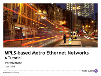
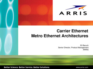
service provider is not be able to reach all the subscriber sites, the provider canuse a third party, an operator, to provide service to all the subscriber’s locations.CE 2.0 CertificationPrior to CE 2.0, the MEF used to certify compliance to each specification document separately. Thus,certification was done separately for MEF 9 and MEF 14.CE 2.0 is not defined in a single document or specification; it is a set of features and services that aredefined in a number of MEF specifications. Hence CE 2.0 certification is provided on a per-servicebasis, rather than on a per-spec basis, as was done previously. The CE 2.0 Certification Blueprint [3]specifies the complete list of attributes to be verified in order to certify each CE 2.0 service. The MEFstill provides certification to the pre-CE 2.0 feature-set, now referred to as CE 1.0.The MEF provides two types of CE 2.0 certifications: for service providers and for equipment vendors.CE 2.0 ServicesCE 2.0 defines eight types of services, summarized in Table 1. While CE 1.0 includes three services,EPL, EVPL and EP-LAN, this set has been extended in CE 2.0 to include eight services, as shown inTable 1.Port-based ServiceVLAN-based eEVP-TreeE-AccessAccess EPLAccess EVPLTable 1. CE 2.0 Services (services in dark shade were also present in CE 1.0).This subsection surveys these eight service types [4].We start by defining two commonly used terms in MEF specifications (depicted in Figure 1):UNIThe User-Network Interface is the interface connecting the Customer Equipment (CE) tothe carrier Ethernet network.EVCAn Ethernet Virtual Connection is an association between two or more UNIs.Figure 1. Ethernet Virtual Connection (EVC)E-LineAn E-Line is a point-to-point EVC between two UNIs. An E-Line can have two possible flavors: Port-based Ethernet Private Line (EPL). This mode (Figure 2) uses all-to-one bundling,where all traffic sent from a CE to a given port (UNI) is bundled as a single EVC.Carrier Ethernet 2.0: A Chipmaker’s Perspective3
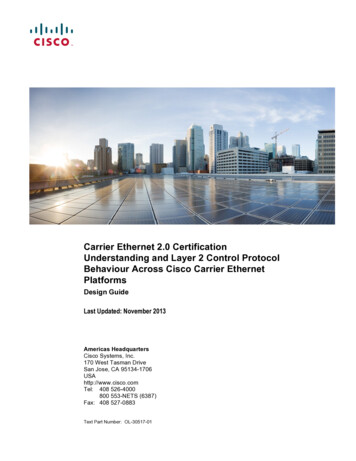
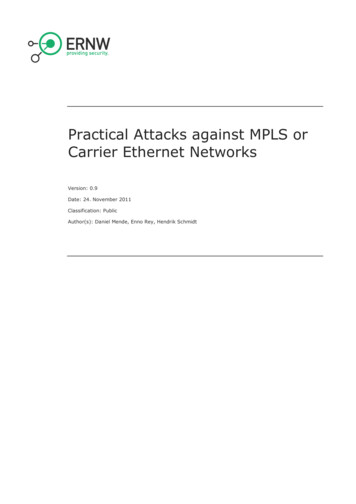
VLAN-based Ethernet Virtual Private Line (EVPL). This mode (Figure 3) performsservice-multiplexing based on VLANs, i.e., each customer VLAN is bound to a separate EVC.Figure 3. Ethernet Virtual Private Line (EVPL):VLAN-based service multiplexingFigure 2. Ethernet Private Line (EPL):port-based all-to-one bundlingE-LANAn E-LAN is a multipoint-to-multipoint EVC that can be either port-based or VLAN-based, asillustrated in Figure 4 and Figure 5, respectively.Figure 4 illustrates a network in which the customer is spread over three sites, and an all-to-onebundling is used to bind customer traffic to the EVC. In Figure 5 two EVCs are used; a point-to-pointEVC between site 1 and site 2, and a multipoint-to-multipoint EVC between sites 1, 3, and 4. VLANbased multiplexing is used in site 1 to bind each VLAN to the respective EVC.Figure 4. Ethernet Private LAN (EP-LAN):port-based all-to-one bundlingFigure 5. Ethernet Virtual Private LAN(EVP-LAN): VLAN-based service multiplexingE-TreeAn E-Tree service is a rooted-multipoint EVC, where one UNI (the root) is permitted to send andreceive traffic to other UNIs (leafs), but leaf-to-leaf communication is not permitted.Figure 6 illustrates an example of a port-based E-Tree. The network in Figure 7 uses VLAN-basedmultiplexing of an E-Tree and an E-Line.Figure 6. Ethernet Private Tree (EP-Tree):port-based all-to-one bundlingCarrier Ethernet 2.0: A Chipmaker’s Perspective4
Figure 7. Ethernet Virtual Private Tree(EVP-Tree): VLAN-based service multiplexingE-AccessAn E-Access service defines interconnection between service providers; it allows an access provider(Figure 8) to reach out-of-franchise customer locations by using an Operator Virtual Connection(OVC), operated by a retail service provider. E-Access appears to the customer as a conventional EVC,provided by the access service provider. E-Access can provide both port-based and VLAN-basedservices. The interface between the provider network and the operator network is called ExternalNetwork to Network Interface (ENNI).Figure 8. E-Access: Reaching out-of-franchise Customers via a Retail Service ProviderCE 2.0 from a Chipmaker’s PerspectiveAs noted above, the MEF provides CE 2.0 certification for services and for equipment; nocertification program has been defined for network equipment silicon. This fact is not surprising, asMEF specifications define functionality that affects both the data plane and the control plane, whereassilicons mostly implement the data plane functionality, and most of the control plane functionality istypically implemented in software.Hence, CE 2.0 certification is a product of cooperation between network equipment vendors and chipvendors, allowing the combined product to be certified by the MEF.Figure 9. CE 2.0 Certification Process: Cooperation betweenSilicon Vendor and Network Equipment VendorCarrier Ethernet 2.0: A Chipmaker’s Perspective5
What does CE 2.0 require from packet processor chips?CE 2.0 is defined by a number of MEF specifications, and includes a rich set of features and complexfunctionality. Hence, CE 2.0 has many implications on packet processor chips, including: Port-based and VLAN-based packet classification. VLAN tag manipulations. Service OAM. Provider tunneling technologies, such as VPLS and MPLS. Multi-CoS traffic differentiation. Traffic metering (policing).Marvell CE 2.0 FeaturesThe Marvell Prestera -DX family of packet processors includes a comprehensive feature set thataddresses the requirements of Carrier Ethernet networks, and specifically of CE 2.0.The Marvell Prestera-DX family includes two architectural building blocks that are key enablers of CE2.0, eBridge and FlexOAM.Figure 10. Marvell eBridge ArchitectureFigure 11. Marvell FlexOAM ArchitectureMarvell eBridge Architecture. The extended-bridging (eBridge) architecture is a unifiedarchitecture, implementing a hardware-based virtualization of interfaces and switching domains. Itextends the traditional physical bridge port paradigm to a flexible paradigm supporting virtualinterfaces called Extended Ports or ePorts. In addition, the architecture extends the 4K Virtual LAN(VLANs) defined by IEEE 802.1Q into larger switching/flooding domains called Extended VLANs oreVLANs.The eBridge architecture is ideal for implementing CE 2.0: The eBridge architecture provides a straightforward and scalable abstraction for EVCs, usingePorts. eBridge allows flexible VLAN-based multiplexing and VLAN tag manipulations. eBridge enables an intuitive and scalable use of provider tunneling technologies such as VPLS,MPLS and PBB, as:oEVCs and tunneled EVCs are represented by the ePort abstraction, which is independentlymapped into a physical interface (e.g., physical port, link aggregation group).oSwitching/flooding domains are represented by the eVLAN abstraction, independently fromthe switching/flooding methods; an 802.1Q VLAN, a VPLS VSI, as well asswitching/flooding domains of other provider technologies are supported using a singleeVLAN abstraction that is not technology specific.Carrier Ethernet 2.0: A Chipmaker’s Perspective6
eBridge flexible configuration of ePort/eVLAN abstraction attributes, and the independency ofthese attributes from the actual physical interface they are mapped to, allows for a single-passline-rate any-to-any encapsulation conversion, including multi-target replications, where eachcopy may be encapsulated independently. This is an extremely powerful capability for ENNI andUNI nodes that interface multiple network encapsulation technologies. eBridge end-to-end Quality of Service (QoS) support - flexible ingress and egress QoS mappingtables enable network edge nodes that interface multiple QoS domains, a smooth and extremelyflexible QoS translation upon network/technology boundary cross, thus allowing the provider toensure end-to-end SLA preservation over multiple network technologies.Marvell FlexOAM Architecture. FlexOAM provides generic hardware support for real-time processingof OAM traffic.FlexOAM uses a programmable flow classification engine, allowing support for various existing OAMprotocols, as well as proprietary or future ones.Network failures, also known as loss of connectivity, are detected by the FlexOAM keepalive engine,which is in charge of reception and transmission of keepalive messages. FlexOAM performs accurateloss and delay measurement, using hardware-based packet counters and timestamping.Since OAM is one of the key building blocks of CE 2.0, FlexOAM is an important CE 2.0 enabler.One Architecture: Three Features, Eight ServicesAs shown in Table 2, the three major features of CE 2.0 - multi-CoS, manageability andinterconnection, are addressed by the Marvell Prestera-DX family, with eBridge and FlexOAM as thekey vant Features in Marvell Prestera-DX Devices The Marvell Prestera-DX advanced CoS architecture allows for multiCoS traffic differentiation. Shaping, scheduling, metering and tail-dropping mechanisms can beapplied to differentiate between classes of service. OAM: Marvell FlexOAM architecture provides flexible support for variouscontemporary and future OAM protocols. Ingress/egress traffic management: the Marvell Prestera -DX deviceincludes both an Ingress Policer engine and an Egress Policer engine,allowing the definition of bandwidth profiles both on the ingress andegress of the EVC. Traffic management per UNI, per EVC, per CoS: metering can beperformed based on various criteria: per-flow, per-ePort, per-physicalport, per-eVLAN, or, can be flexibly configured to be based on anycirteria or packet header field, allowing the bandwidth enforcement tobe based on any of the three criteria defined in CE 2.0.The eBridge architecture and the flexible VLAN manipulation capabilitiesprovide the necessary tools for topologies that span multiple providers,including E-Access. Every OVC in the E-Access network is represented byan ePort in the ENNI.Table 2. Supporting the CE 2.0 FeaturesCarrier Ethernet 2.0: A Chipmaker’s Perspective7
Table 3 summarizes the Marvell Prestera-DX features that enable the CE 2.0 services.ServiceE-LineE-LANE-TreeE-AccessRelevant Features in Marvell Prestera-DX DevicesEPL EVPL EP-LAN EVP-LAN EP-Tree EVP-Tree Access EPL AccessEVPL Interface virtualization using the eBridge architecture: ePortsand eVLANs. Flexible VLAN translation and QinQ. Flexible tunneling and L2VPN support: MPLS, VPLS, PBB. E-Tree support using root/leaf indication [6].Table 3. Enabling CE 2.0 ServicesConclusionCarrier Ethernet 2.0 is the second generation of features and services in carrier networks. The CE2.0 feature set encompasses both the data plane and the control plane. Hence, packet processorsilicon cannot be CE 2.0 certified as-is; only a full solution that includes both silicon and software canreceive the CE 2.0 certification.Marvell Prestera-DX devices provide a wide set of features that enable a CE 2.0-compliant system,including eBridge, a flexible hardware-based interface virtualization architecture, and FlexOAM, anenhanced hardware-based OAM solution.Carrier Ethernet 2.0: A Chipmaker’s Perspective8
About the AuthorsTal MizrahiFeature Definition ArchitectTal Mizrahi is a feature definition architect at Marvell. With 15 years of experience in networking,network security, and ASIC design, Tal has served in various positions in the industry, includingsystem engineer, team leader and, for the past 8 years, an architect for Marvell's networking productline. Tal received his BSc. and MSc. in Electrical Engineering from the Technion, Israel Institute ofTechnology. Tal is an active participant in the Internet Engineering Task Force (IETF), the OpenNetworking Foundation (ONF), and serves as the security editor of the IEEE 1588 working group. Talis a MEF Carrier Ethernet 2.0 Certified Professional (MEF-CECP).Uri SafraiSoftware and Solution ArchitectUri has over 17 years of networking experience. Prior to his current position, Uri worked at GalileoTechnology until its acquisition by Marvell in 2001, and since then has held a variety of technologicalpositions at Marvell. At his former role as a switch architect of the Prestera line of packet processors,Uri was involved with definition and micro-architecture of networking features, protocols, and variousASIC engines and mechanisms, as well as led the definition of the Prestera eBridge virtualized dataplane architecture. Since 2010, Uri represents Marvell at the Metro Ethernet Forum (MEF), andrecently joined the ONF Chipmakers Advisory Board (CAB).Carrier Ethernet 2.0: A Chipmaker’s Perspective9
AcronymsBFDBidirectional Forwarding DetectionCE 2.0Carrier Ethernet 2.0CECustomer EquipmentCoSClass of ServiceENNIExternal Network to Network InterfaceEPLEthernet Private LineEVPLEthernet Virtual Private LineEP-LANEthernet Private LANEVP-LANEthernet Virtual Private LANEP-TreeEthernet Private TreeEVP-TreeEthernet Virtual Private TreeEVCEthernet Virtual ConnectionMPLSMultiprotocol Label SwitchingMPLS-TPMPLS Transport ProfileNNINetwork-to-Network InterfaceOAMOperations, Administration and MaintenanceOVCOperator Virtual ConnectionPBBProvider Backbone BridgingPEProvider EdgeQoSQuality of ServiceSLAService Level AgreementUNIUser Network InterfaceVLANVirtual Local Area NetworkVPLSVirtual Private LAN ServicesVSIVirtual Switching InstanceCarrier Ethernet 2.0: A Chipmaker’s Perspective10
References[1]Metro Ethernet Forum, “A New Generation of Carrier Ethernet – Overview Presentation”, 2012.[2]Metro Ethernet Forum, “Carrier Ethernet 2.0 Services - Technical Foundation Document”, 2012.[3]Metro Ethernet Forum, “Carrier Ethernet 2.0 Certification Blueprint”, version 1.1, 2012.[4]Metro Ethernet Forum, “An Overview of MEF 6.1, 6.1.1, 10.2, 10.2.1 Carrier Ethernet Definitions and Attributes”, F New Generation of Carrier Ethernet - Overview /CE2.0/CE 2-0 Technical Foundation Document v2 /CE2.0/Carrier Ethernet 2.0 Certification Blueprint - VERSION 1 l Specifications/PPT/Overview of MEF6-1 10-2 and 10-2-1 v8-Mar-272012.ppt[5]Metro Ethernet Forum, “An Overview of the MEF”, tion/Overview of the Work of the MEF 20130610.pptx[6]Jiang, Y., Yong, L., Paul, M., Jounay, F., Balus, F., Henderickx, W., Sajassi, A., “Ethernet-Tree (E-Tree) Support in VirtualPrivate LAN Service (VPLS)”, draft-ietf-l2vpn-vpls-pe-etree-03 (work in progress), IETF, pls-pe-etree[7]T. Mizrahi, N. Sprecher, E. Bellagamba, Y. Weingarten, "An Overview of Operations, Administration, and Maintenance (OAM)Tools", RFC 7276, 2014.http://tools.ietf.org/html/rfc7276[8]T. Mizrahi, I. Yerushalmi, "The OAM Jigsaw Puzzle", technical white paper, Marvell, 2011.[9]Wikipedia, “Metro Ethernet Forum”, ll OAM Puzzle 001 white paper.pdfhttp://en.wikipedia.org/wiki/Metro Ethernet ForumMarvell Semiconductor, Inc.5488 Marvell LaneSanta Clara, CA 95054, USATel: 1.408.222.2500www.marvell.comCarrier Ethernet 2.0: A Chipmaker’s PerspectiveCopyright 2015. Marvell International Ltd. All rights reserved.Marvell, the Marvell logo and Prestera are registered trademarks ofMarvell or its affiliates. Other names and brands may be claimed as theproperty of others.11
the carrier Ethernet network. EVC An Ethernet Virtual Connection is an association between two or more UNIs. Figure 1. Ethernet Virtual Connection (EVC) E-Line An E-Line is a point-to-point EVC between two UNIs. An E-Line can have two possible flavors: Port-based Ethernet Private Line (EPL). This mode (Figure 2) uses all-to-one bundling,