Transcription
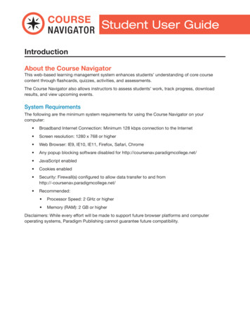
Reference Manual00809-0100-4423, Rev ABMay 2014Emerson Smart Wireless Navigator
Smart Wireless NavigatorMay 2014Reference Manual00809-0100-4423, Rev ABContentsTheory of operation . . . . . . . . . . . . . . . . . . . . . . . . . . . . . . . . . . . . . . . . . . . . . . . . . . . . . . . . . page 3Installing the Navigator machine . . . . . . . . . . . . . . . . . . . . . . . . . . . . . . . . . . . . . . . . . . . . . . page 3Launching Navigator . . . . . . . . . . . . . . . . . . . . . . . . . . . . . . . . . . . . . . . . . . . . . . . . . . . . . . . . page 5Navigator security . . . . . . . . . . . . . . . . . . . . . . . . . . . . . . . . . . . . . . . . . . . . . . . . . . . . . . . . . . . page 5Adding networks to Navigator . . . . . . . . . . . . . . . . . . . . . . . . . . . . . . . . . . . . . . . . . . . . . . . . page 7Understanding the Navigator - general layout and terminology . . . . . . . . . . . . . . . . . . . page 9Using the Navigator for network planning and commissioning . . . . . . . . . . . . . . . . . . . . page 11Using the Navigator for network management . . . . . . . . . . . . . . . . . . . . . . . . . . . . . . . . . . page 13Using the Navigator for network maintenance . . . . . . . . . . . . . . . . . . . . . . . . . . . . . . . . . . page 16Advanced Navigator functions . . . . . . . . . . . . . . . . . . . . . . . . . . . . . . . . . . . . . . . . . . . . . . . . page 18Shutting down Navigator . . . . . . . . . . . . . . . . . . . . . . . . . . . . . . . . . . . . . . . . . . . . . . . . . . . . page 19Service and troubleshooting . . . . . . . . . . . . . . . . . . . . . . . . . . . . . . . . . . . . . . . . . . . . . . . . . . page 192Smart Wireless Navigator
Reference ManualSmart Wireless Navigator00809-0100-4423, Rev AB1.1May 2014Theory of operationThe Emerson Smart Wireless Navigator is a stand-alone network infrastructure managementtool. It brings together several Emerson Smart Wireless software tools to streamline wirelessnetwork experience. Delivered on a specially designed computer, the Navigator helps to planand deploy networks, manage devices and networks, and easily make maintenance plans.1.2Installing the Navigator machine1.2.1ContentsThe Smart Wireless Navigator is a three-box package containing the following:Box 1 (Dimensions: 24 x 21.5 x 14.5)(Italicized items are not required for recommended setup)Quantity 1 - Computer workstation tower, containing all Smart Wireless Navigator Software,with attached licensing dongleQuantity 1 - USB keyboardQuantity 1 - USB mouseQuantity 1 - 6' power cord for computer tower (NEMA 5-15, Type B, 125 V)Quantity 3 - Additional power cords possible (if designated when ordering); 6' power cords; onefor computer tower, two for displaysQuantity 1 - Setup and Features Information BookletQuantity 1 - Safety and Regulatory Information BookletQuantity 1 - Smart Wireless Navigator Product ManualQuantity 2 - DVI-to-VGA Adapter (white)Quantity 2 - Display Port-to-DVI AdapterQuantity 2 - Resource Media CDQuantity 1 - Applications CDBox 2 and 3 (Dimensions: 23 x 16 x 8.5)(Boxes 2 and 3 are identical. Italicized items are not required for recommended setup)Quantity 1 - 22" LCD display monitorQuantity 1 - Monitor standQuantity 1 - 6' power cord for monitor (NEMA 5-15, Type B, 125 V)Quantity 1 - 6' DVI Monitor Cable (white)Quantity 1 - Monitor Setup GuideQuantity 1 - Product Information GuideQuantity 1 - 6' VGA Monitor CableQuantity 1 - 6' HDMI Monitor CableQuantity 1 - Drivers and Documentation CDSmart Wireless Navigator3
Reference ManualSmart Wireless Navigator00809-0100-4423, Rev ABMay 20141.2.2Setting up the computer1.Set up the monitors as instructed by the Monitor Setup Guide provided in boxes 2 and 3. The white DVI monitor cables are recommended for the best display resolution. Box 1 contains region-specific power cords (outside of NEMA type).2.Set up the workstation as instructed by the Setup and Features Information Guideprovided in Box 1. The Monitor Cables referenced in step 1 will connect to the back of the workstation.NoteBe very cautious not to damage the USB licensing dongle located on the back of theworkstation.1.2.33.Connect the local area network ethernet cord to the back of the workstation.4.Power up the Navigator by pressing the power button on the front of the workstation.5.Read and consider the Microsoft End User License Agreement.6.Log into the Navigator workstation.a.Username: Administratorb.Password: navigatorAssigning an IP addressBy default, the Navigator is set up to connect to a dynamic IP architecture and be assigned an IPaddress by dynamic IP address allocation (DHCP).Consult your IT department to determine if your site runs a dynamic or static architecture. Allstatic IP information will come from IT.A static IP architecture means that a specific IP address will be assigned to the Navigator box. Toconfigure the Navigator to connect to a static IP architecture:1.Open the Windows Start Menu.2.Select “Control Panel.”3.Click “Network and Sharing Center.”4.In the left panel, click “Change Adapter Settings.” This will open a list of NetworkInterface Cards.5.Right click on Navigator Primary and select Properties.6.Under Properties dialog box, highlight IP Version 4 and click Properties.NoteThe radio button “Obtain an IP address automatically” will be selected. This means the IPaddress will be obtained from a DHCP (Dynamic Host Configuration Protocol) server.7.4Click “Use the following IP address” and enter in the IP address assignment for theNavigator.Smart Wireless Navigator
Reference ManualSmart Wireless Navigator00809-0100-4423, Rev AB1.2.4May 2014Windows user permissionsWhen installing the Navigator, it is necessary to consider user permissions. The default user forthis computer is an Administrator user. An Administrator has privileges to add or deleteprograms, among other capabilities. To restrict the General Navigator user from theseprivileges, create a General User account in the Control Panel. It is recommended to run theNavigator on a Windows user with the least privileges possible.1.2.5Windows passwordsWhen installing the Navigator, it is strongly recommended, for security purposes, to change thepassword for the Windows log in. Follow best practices and site/corporate IT policies to create astrong, non-default password.1.2.6Windows updatesIt is strongly recommended to keep the computer up to date with the latest Windows patchesand security updates. Follow site or corporate IT and security policies when implementing andmanaging the Navigator system.1.3Launching NavigatorAfter logging into the Navigator workstation, the Navigator program will auto launch. Pleaseallow time for Navigator to load; this may be several minutes for initial launch.1.4Navigator securityA user must be logged into the Smart Wireless Navigator to access the informationand launch the programs it contains. To log in to Navigator, simply click the “log in”button in the Title Bar. A prompt will ask for a username and password. Enter theappropriate username and password. Several design tools and applications may require a log in.1.4.1Navigator passwordsThe Smart Wireless Navigator has two levels of user permissions, administrative and generaluser. There is one administrative account and three general accounts. The administrativeaccount, “Supervisor,” has a default password of “Admin”.When commissioning the Navigator, it is strongly recommended, for security purposes, tochange the password for the Navigator profile log ins. Follow best practices and site/corporateIT policies to create strong, non-default passwords.The Administrator has the authority set up and change all the user accounts andpasswords, but the usernames cannot be changed. Click on the “Settings” button inthe Function bar. The change password capability can be found on the bottom of thescreen.Smart Wireless Navigator5
Reference ManualSmart Wireless Navigator00809-0100-4423, Rev ABMay 2014Table 1-1. User accounts and passwordsDefault usernameSupervisorUser 1User 2User 3Default passwordAdminPassword1Password2Password3Account typeAdministrativeGeneral UserGeneral UserGeneral UserRestrictionsNone, Full AccessAdd new Gateways, Settings(General, Application,Maintenance)To protect the Navigator information and programs when not in use, or to switchusers, click the “log out” button in the Title Bar.1.4.2AMS Wireless Configurator or AMS Device ManagerLaunching the design sub-menu and selecting the Device Design button with openAMS Wireless Configurator or AMS Device Manager, depending on your Navigatortype. A prompt will ask for the username and password associated with this AMSaccount. AMS Wireless Configurator has a default username/password of admin/[no password].When commissioning the AMS Wireless Configurator within the Navigator, it is stronglyrecommended, for security purposes, to change the password. Follow best practices andsite/corporate IT policies to create a strong, non-default password. The username and passwordof AMS Device Manager will match the username/password of the main AMS system.1.4.3Server Plus Connect for AMS Device ManagerTo connect to a different Server Plus Station, the Client SC Station must first be addedto the Station Configuration of the Server Plus Station (see Related Topics for moreinformation). If this requirement is not met, an error (This PC is not licensed forClient-Server operation) displays on the Client SC Station when AMS Device Manager is started.To connect to a different Server Plus Station if AMS Device Manager is closed on the Client SCStation:1.In Network Configuration on the Client SC Station, remove all configured systeminterfaces (other than HART Modem).2.Select Start All Programs AMS Device Manager Server Plus Connect.3.Select the desired Server Plus Station PC from the Server Plus Station drop-down list orenter the PC name in the box and click Connect.4.Click Yes to launch AMS Device Manager after making the connection; No to connectwithout launching AMS Device Manager; or Cancel to keep the existing connection.5.After the connection is made, click Close.To connect to a different Server Plus Station if AMS Device Manager is running on the Client SCStation:1.If no system interfaces (other than HART Modem) are configured on the Client SCStation, select Tools Server Plus Connect.2.Select the desired Server Plus Station PC from the Server Plus Station drop-down list orenter the PC name in the box and click Connect.3.Click Yes to launch AMS Device Manager after making the connection, No to connectwithout launching AMS Device Manager, or Cancel to keep the existing connection.4.After the connection is made, click Close.After the Server Plus connection has been established, you can view the entire networkconfiguration of the Server Plus in the Device Explorer view on the Client SC.6Smart Wireless Navigator
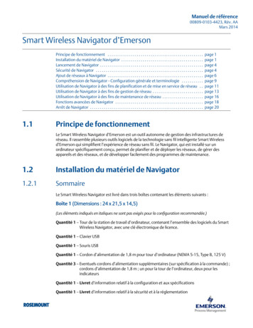
Reference ManualSmart Wireless Navigator00809-0100-4423, Rev AB1.4.4May 2014Gateway interfaceFrom the Gateway level view, launching opening the design sub-menu and selectingthe Gateway Interface button will open the Gateway Interface. To access the GatewayInterface, enter the username and password associated with that Gateway. This is notusually the username and password of the Navigator.1.5Adding networks to NavigatorThe Smart Wireless Navigator makes it easy to add networks from the Administrator account.Click the Settings button on the function bar. Select the checkbox next to the “GatewayConfiguration - Add New Gateways” option. When this box is checked, networks can be addedor removed from the Detailed Gateway Dashboard Display Field.Figure 1-1. Gateway configuration - adding new gateway optionClick the Home button. From the Home screen, select the section or area to which the Gatewayshould be added.Figure 1-2. Area selection tabTo add a Gateway, type the IP address in the available white space. Press the Enter button.Figure 1-3. Adding the IP addressIf the Gateway is not secure, the network will be immediately added. If the gateway is a securegateway, the Navigator will prompt for a username and password. This is the same usernameand password used to access the Gateway Interface.NoteIf the Port Number of the Gateway has been changed to a non-default value, the Navigator willprompt for the Port Number. This can be found in the Security sub-menu of the GatewayInterface.Smart Wireless Navigator7
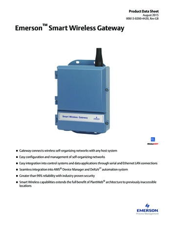
Reference ManualSmart Wireless Navigator00809-0100-4423, Rev ABMay 20141.5.1Considerations - navigation tab customizationThe default labels of the Gateway Navigation tabs refer to the numerical designation of theGateways.Figure 1-4. Gateway navigation tabsIn large deployments of wireless networks, it may be beneficial to organize the Gatewaysaccording to their applications, or physical process or geographical location. The Smart WirelessNavigator contains a feature that will rename the main screen navigation tabs to represent thesecustomized areas.To customize the navigation tabs, click the Settings button on the function bar. Findthe Gateway Navigation Tab Configuration area. This contains five writable parameterfields. Clicking on these fields will bring up a prompt for the new name to be entered,limited to eighteen characters.Figure 1-5. Gateway navigation tab configuration1.5.2Adding networks to AMS Wireless Configurator1.Launch the Network Configuration utility.a. Click the Windows Start button from the main taskbar.b. Click All Programs.c. Open the AMS Wireless Configurator folder.d. Click Network Configuration.82.Click Add.3.Select Wireless Network from the list of networks in the Select Network ComponentType dialog box. (The Wireless Network selection is only available if you are licensed forthe Wireless Interface).4.Click Install.5.Follow the instructions in the “Add Wireless Network” wizard.6.Launch AMS Wireless Configurator from Navigator or from All Programs in theWindows menu.7.Perform a Rebuild Hierarchy operation on the network by right-clicking the top-levelWireless network icon in Device Explorer and selecting Rebuild and Identify Hierarchy.8.Perform a Scan New Devices operation on the network by right-clicking the top-levelWireless network icon in Device Explorer and selecting Scan New Devices.Smart Wireless Navigator
Reference ManualSmart Wireless Navigator00809-0100-4423, Rev AB1.5.3May 2014Adding networks to AMS Wireless SNAP-ONReference the SNAP-ON manual in the Help menu for detailed instructions.Once a scaled drawing of the plant has been loaded, networks can be imported from AMSWireless Configurator. From the function bar, select Diagram, then Import Wireless Networks.Select the network to be imported.NoteThis can only be completed once the networks have been added to AMS Configurator, and AMSConfigurator is running.1.5.4Adding networks to SteamLogic softwareReference the SteamLogic manual in the Navigator Help menu for detailed instructions.SteamLogic will need to be registered before it can be commissioned. Register online asoutlined in the product manual located in the Navigator or program help menu.1.61.Click the Set Up tab.2.Enter the network IP address, HART IP Port, and Descriptions in the fields and click Save.Understanding the Navigator - general layout andterminologyEvery screen in the Smart Wireless Navigator contains the Title Bar, Display Field, and FunctionBar.1.6.1Navigator title barFigure 1-6. Navigator Title BarThe Title Bar contains general product identification and user information, and an option foruser log in and log out. It displays the time as configured by the Windows task bar and a Helpfunction.The Help button opens a screen that will provide links to a selection of manuals andhelp menus. It also contains an electronic copy of this Navigator manual.Smart Wireless Navigator9
Reference ManualSmart Wireless Navigator00809-0100-4423, Rev ABMay 20141.6.2Navigator display fieldThe Navigator display field is the area in between the title and function bars.Figure 1-7. Navigator Display Field1.6.3Navigator function barFigure 1-8. Navigator function barThe Navigator function bar contains all the main functions for Navigator operations.Table 1-2. Navigator Function BarButtonorNameFunctionHomeClicking the Home button will return a user to the Overviewscreen, where all the networks are listed.Back orForwardThe Back or Forward buttons will return the display field to thelast screen shown, either back in navigation or forward innavigation.TrendsOpens Trending function. Description on page 19.ReportsOpens a sub-menu that allows a user to generate a report onnetwork health or power module status.DesignOpens a sub-menu that contains all functions related to design.The sub-menu contains Gateway Interface, Asset ManagementProgram, Wireless Network Planning Tool, Gateway CapacityEstimator, and Power Module Life Estimator.Opens third party application options. Description onApplications page18.Print Screen Will print the screen shown in Navigator display field.Settings10Opens a variety of categories for Navigator settings, includingGeneral, Applications, and Navigator Maintenance. Requiresadministrator permissions.Smart Wireless Navigator
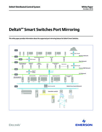
Reference ManualSmart Wireless Navigator00809-0100-4423, Rev ABMay 20141.7Using the Navigator for network planning andcommissioning1.7.1Network planning tool - AMS Wireless SNAP-ONThe Smart Wireless Navigator has integrated a planning tool for mapping networklayouts for planning, the AMS Wireless SNAP-ON. This application enables importing aplant image or process unit drawing for customized network planning, with a 'dragand drop' capability to add devices.The planning tool can check the design against Emerson Wireless best practices and graphicallyshow deviations, enabling pre-installation optimization measures to be taken.Locate the product manual in the Navigator or program Help menu for guidance on productfunctionality and additional features.1.7.2Smart Wireless Gateway Capacity EstimatorAn accurate evaluation of network capacity can be determined by using the SmartWireless Gateway Capacity Estimator, which calculates the network capacity using acombination of the network's type of instrumentation and update rates.Figure 1-9. Smart wireless gateway capacity estimatorSmart Wireless Navigator11
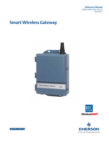
Smart Wireless Navigator1.7.3Reference Manual00809-0100-4423, Rev ABMay 2014Smart Wireless Power Module Life EstimatorOnce the update rate required for the instrumentation has been determined, it'srecommended to realistically evaluate the impact of these update rates. The SmartWireless Power Module Estimator provides estimates for Power Module life by acombination of wireless device type, update rate, and environmental variables. This tool willprovide valuable information for maintenance expectations by estimating how often PowerModules will need to be replaced.Figure 1-10. Power Module Life Estimator1.7.4AMS Configurator or Device ManagerDevice configuration may be needed after initial network commissioning. The SmartWireless Navigator contains a Wireless Configuration application. Depending onwhich version purchased, Navigator will contain an integrated AMS WirelessConfigurator or will connect to an existing AMS Device Manager. A username and password isrequired to access these tools. This will be different from the Navigator username and password.Locate the product manual in the Navigator or program Help menu for guidance on productfunctionality and additional features.1.7.5Gateway interfaceOnce a Gateway has been added, the Gateway Interface can be accessed for planningand commissioning functions, such as checking/changing Network ID and Join Key,enabling Active Advertising, verifying a device has joined the network, etc. TheGateway Interface can be opened from a Gateway level display field through the designsub-menu. (This level of page can be identified by locating the Gateway Identification bar,page 16.) A username and password will
1.4.2 AMS Wireless Configurator or AMS Device Manager Launching the design sub-menu and selecting the Device Design button with open AMS Wireless Configurator or AMS Device Manager, depending on your Navigator type. A prompt will ask for the username