Transcription
Telecommunications InfrastructureStandard for Data CentersANSI/TIA-942Chris DiMinicocdiminico@ieee.orgMC CommunicationsIEEE 802.3 HSSG
Data Center Standards ANSI/TIA-942 TelecommunicationsInfrastructure Standard for Data Centers Co-chairs: Chris DiMinico & Jonathan Jew Published 2005 – available through TIA atwww.tiaonline.orgANSI/NECA/BICSI-002 Data Center Designand Implementation Best Practices co-chairs: Jonathan Jew & John Kacperski best practices – complements TIA-942 –2007 targetIEEE 802.3 HSSG
Who Developed TIA-942? Developed by the TIA TR-42.1.1 NetworkDistribution Nodes subcommittee as ProjectNo. 3-0092Participants included: Architecture & Engineering Firms Consultants End Users ManufacturersIEEE 802.3 HSSG
Purpose of TIA-942 Encourage early participation of telecomdesigners in data center design processFill a void by providing standards for planningof data centers, computer rooms, serverrooms, and similar spaces.The standard encompasses much more thanjust telecommunications infrastructure.Close to half of the technical content dealswith facility specifications.IEEE 802.3 HSSG
Purpose of TIA-942 Define a standard telecommunicationsinfrastructure for data centers Structuredcabling system for data centers usingstandardized architecture and media Accommodates a wide range of applications (LAN,WAN, SAN, channels, consoles) Accommodates current and future protocols(e.g., 10 GbE ) Replaces unstructured point-to-point cabling thatuses different cabling for different applicationsIEEE 802.3 HSSG
Purpose of TIA-942 Specifications for data centertelecommunications pathways and spacesRecommendations on media and distance forapplications over structured cablingEstablish a standard for data center tiers toreplace several proprietary standards. TheTIA data center tier standard is: A tool to evaluate existing data centers A tool to communicate designrequirementsIEEE 802.3 HSSG
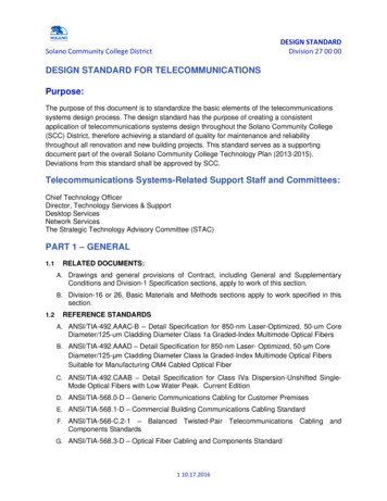
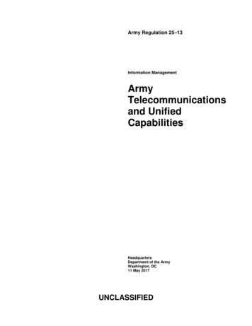
Unstructured CablingCDEFGHIJKLMNOPQRSTUHeater - A/C1TABLE247-7589ABACADAEAFTABLEFI L EF IL ECABINETCABI NETAIAJAKALAMANAOAPAQF IL ECABINETFIL ECABINETPOMONAA/C UNIT#6ARASHPPRINTERC D ROMSCANNERUNITN ETWORKCABINETE7NETWOR KCABI NETI1NE TWORKCABI NETI2NE TWORKCABI NETI3I5NE TWORKC ABINETI4NETWORKCAB INE TNETWORKCABINETI7NETWOR KC ABINETI6CAB INE TI8DESKNETWOR KH8N ETW OR KCABINETH7N ETW OR KCABINETH6NETWORKCABINETG7IBMCABCABINETF6N ETWOR KCABINETG6N ETW ORKC ABINETF5NETWORKCABINETG5N ETW ORKC ABINETNETWORKC ABINETE6IBM3745-A11IBM3746-900NETWORKC ABINETIBMTAPE RACKPOMONAA/C UNIT#8TAPE RACKNETWORKCABIN ETH4NETWORKCABIN ETG4N ETW ORKC ABINETF3NETWORKNETWORKCABIN ETN ETW ORKC ABINETF2CABIN ETH3NETWORKCABIN ETH2IBMDASDIBMS-390R34IBMDASDF4NETWORKCABIN ETH1G3NETWORKCABIN ETG2LANCABINETF1NETWORKC ABINETE4NETWORKC ABINETE3NETWORKC ABINETE2NETWORKC ABINETE13745-41DIBM3745-17AIBM3745-L13SAACABIN ETD2N ETW OR KCABINETA6NETW OR KCABINETNETWORKCABINETC6B7N ETW OR KN ETWOR KCABINETA5N ETW ORKE511AHHeater - A/CPOMONAA/C UNIT#7N ETW OR KCABINETNETWORKCABIN ETH58AGAT &T710AADEFINIT Y69ZTABLEHe ater - A/C5YNETW OR KCABINETC5CABINETB6HALONPANELNETWORKCABINETA4NETW OR KCABINETC4N ETWOR KCABINETB5NETW OR KCABINETC3N ETWOR KCABINETB4N ETW OR KCABINETNETW OR KN ETWOR KA2CABINETC2CABINETB3NETW OR KCABINETC1N ETWOR KCABINETB2N ETW OR KCABINETA3NETWORKSAACABIN ETCI SCOROU TE R4XCONS OLE3WHeater - ELEASEC ABI NE TA1BPA C BELLAD1N ETWOR KCABINETB1NETWORKCABIN ETG112247-75381314STORAGEC ABINE TTAPE RACK15IBMAS -400IBMAS-400INSTALL A CABLE WHEN YOU NEED IT(SINGLE-USE, UNORGANIZED CABLING)TABLE16IEEE 802.3 HSSGLOCKERSTORAGECABINETLIEBERTPDU 174CABINET3174CABINET3174CABINET
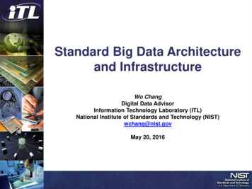
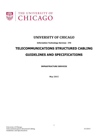
Structured CablingBCDEFGHIJKLMNOPQRSTUVHeater - A/C1TABLE247-7589NE TWORKC ABINETI1NETWORKCABINETI2CAB IN ETI4NETWORKCABINETI3NETWORKNE TWORKCABIN ETI6NETWORKC ABI NETI5NETWOR KCAB INE TI7NE TWORKCABI NETI8IDFNETWORKC ABINETH6IDFN ETWOR KC ABINETH5T APE RACKTABLEAEAFAGFIL EFILECABINETFIBER MDF COPPER& COREMDFPOMONAA/C UNIT#8NETWORKC ABINETE7NETWORKCABINETG7NETWORKCABIN ETG6N ETWOR KC ABINETG5NETWORKCABIN ETNETWOR KC ABINETF6NETWOR KC ABINETF5NETWORKCABIN ETF4G4NETWORKCABIN ETF3N ETWOR KC ABINETH3NETWORKCABIN ETG3NETWORKCABIN ETF2N ETWOR KC ABINETH2NETWORKCABIN ETG2LANCABINETF1N ETWOR KC ABINETH1NETWORKCABIN ETG1C ABINETH4TAPE RACKN ETWORKCABINETE6AHAIAJAKALAMANAOCABINETFIL ECABINETFIL ECABINETPOMONAA/C UNIT#6CD ROMSCANN ERAPAQARASHPPRINTERIBMS-390R34IBMDASDIDFIDFIBM 3745sIBMCABNETWOR KNETWORKIBM3745-A11IBM3746-900C ABINETC6NETWORKCABINETB7NETWORKC ABINETC5NETWORKCABINETB6NETWORKC ABINETNETWORKCABINETC ABINETA6CABINETE5N ETWORKCABINETE4N ETWORKCABINETE3N ETWORKCABINETN ETWORKCABINETE1IBMNETWOR KC ABINETA4C4B5NETWOR KC ABINETNETWORKA3C ABINETC3NETWORKCABINETB4NETWORKC -L13SAACABINETD2NETWORKIDFC ABINETC1SAAC ABINETD1IDFIDFF/X247-7543H ALONABORTNETWOR KC ABINETA2NETWORKCABINETB2NETWORKCABINETB1H ALONPANELNETWOR KC ABINETA5N ETWORKE2MainframeIBMDASD11ADHeater - A/CPOMONAA/C UNIT#7NETWORKCABINETH8NETWORKC ABINETH7N ETWOR K10ACUNIT79ABAT&T68AADEFINITYDESK5ZTABLEHeater - A/C4YCISCOROUTE RCON SOLE3XHeater - A/CSTORAGECABINETDESK2WH ALONRELEASEPAC B ELLC A BIN ETA1AIDFIDF IDF12247-7538131415S TOR AGEC AB IN ETTAPE RACKIBMAS-400IBMAS-400STRUCTURED CABLING SYSTEM (ORGANIZED,REUSABLE, FLEXIBLE CABLING)T ABLE16IEEE 802.3 HSSGSTORAGECABINETLIEBERTPDU- CLOC 3174CABINET3174CABINET3174CABINET
Design Elements Cabling DesignFacility DesignNetwork Design Informative annex’s: Provide best practices Annex A - Cabling Design Considerations Annex B- Telecommunications infrastructureadministration Annex C-Access provider information Annex D- Coordination of equipment plans withother engineers Annex E- Data center space considerations Annex F- Site selectionIEEE 802.3 HSSG
Design Elements Cabling Design: Copper and fiber cabling performanceConnectors, cables, distribution hardwareCabling distancesSpace managementFacility Design:Data center sizing Power distribution methodologies Pathways and spaces HVAC, security, operations, and administration. Flexibility, scalability, reliability and spacemanagement IEEE 802.3 HSSG
Design Elements Network Design: Supportof legacy systems Enable rapid deployment of new and emergingtechnologies such as 10 GbE and 10 GbEcopper and fiber applications.IEEE 802.3 HSSG
Relationship of SpacesBUILDING SITEBUILDING SHELLGENERAL OFFICESPACETELECOM ROOMS &EQUIPMENT ROOMSfor spaces outside datacenterOFFICE BUILDINGSUPPORT SPACEDATA OOM(S)TELECOM ROOM(S)for data centersupport spacesCOMPUTER ROOMIEEE 802.3 HSSGDATA CENTERELECTRICAL &MECHANICAL ROOMSSTORAGE ROOMS& LOADING DOCKS
Data Center TopologyEntrance RoomEntranceFacilityCarriersCarriersActive EquipinterconnectOffices, OperationsCenter, Support RoomsSecondary Entrance RoomActive EquipinterconnectActive EquipinterconnectMCMCCarriersCarriersBack ctActive EquipStorage AreaDevicesinterconnectActive ctive EquipActive EquipData CenterIEEE 802.3 HSSG
TIA-942 Spaces Entrance Room (ER) - location of interfacewith campus and carrier entrance facilitiesMain Distribution Area (MDA) – location ofmain cross-connect (MC)Horizontal Distribution Area (HDA) – locationof horizontal cross-connect (HC)Zone Distribution Area (ZDA) – location ofzone outlet (ZO) or consolidation point (CP)Equipment Distribution Area (EDA) – locationof equipment cabinets and racksIEEE 802.3 HSSG
Data Center zontalCablingHCICinterconnectActive EquipinterconnectActive eDistributionAreaActive EquipEquipmentDistributionAreaHorizontal cabling is the cabling from the horizontal cross-connect (in themain distribution area or horizontal distribution area) to the outlet in theequipment distribution area or zone distribution area.IEEE 802.3 HSSG
Horizontal and Backbone Cabling Recognized Cables: a) 100-ohm twisted-pair cable (ANSI/TIA/EIA-568B.2), category 6 recommended (ANSI/TIA/EIA568-B.2-1) b)multimode optical fiber cable, either 62.5/125micron or 50/125 micron (ANSI/TIA/EIA-568-B.3),50/125 micron 850 nm laser optimized multimodefiber is recommended (ANSI/TIA-568-3-1) c)singlemode optical fiber cable (ANSI/TIA/EIA568-B.3) d)75-ohm (734 and 735 type) coaxial cable(Telcordia Technologies GR-139-CORE)IEEE 802.3 HSSG
Horizontal cabling distances The maximum horizontal distance is 90 mindependent of media type.The maximum channel distance includingequipment cords is 100 m.The maximum cabling distance in a datacenter not containing a horizontaldistribution area is: 300 m for an optical fiber channel includingequipment cords.100 m for copper cabling including equipmentcords.IEEE 802.3 HSSG
Backbone Cabling Includes cabling from MDA to ER, HDAOptional cabling between HDAs allowedMaximum backbone cable lengths depend onapplications to be supportedCentralized optical fiber cabling supportedwith interconnect, splice, or pull-through atthe HDAStar topology with no intermediate crossconnectsVarious topologies permit redundancy andflexibility to support various data center sizesIEEE 802.3 HSSG
Computer Room & Entrance RoomRequirements Min clear height of 2.6m/8.5 ftMin door size 1m/3ft wide 2.13/7ft highMin dist floor loading 7.2 kPA/150lbf/ft2,recommended min 12 kPA/250 lbf/ft220 degrees C to 25 degrees C40% to 55% relative humidity (reduces ESD)Any sprinkler systems must be pre-actionsystemCommon bonding network (CBN) –equipotential ground referenceIEEE 802.3 HSSG
Main Distribution Area Location of Main Cross-Connect (MC), thecentral point of distribution for data centerstructured cabling systemCentrally located to avoid exceedingmaximum distance restrictions (typically for E1s, E-3s, T-1s and T-3s)Install separate racks for Fiber, UTP, andcoaxial cable distributionIEEE 802.3 HSSG
Horizontal Distribution Area Location of Horizontal Cross-Connect (HC),the distribution point for cabling to equipmentdistribution areaDistribution LAN, SAN, KVM switches andconsole servers located in HDAMDA may also include an HC for nearbyequipment distribution areaNumber of HDAs depends on the density ofcabling and the size of the data centerIEEE 802.3 HSSG
Horizontal Distribution Area The capacity of the cable tray system and thesize of the cross-connect creates practicallimits on the size of the HCGuideline is maximum of 2,000 4-pair UTP orcoax cable terminations per HDAArrange patch bays to minimize patch cablelengths and to simplify cable management Separate racks for fiber, UTP, and coax Locate switches and patch panels tominimize patch cord lengthsIEEE 802.3 HSSG
Zone Distribution Area Rack, cabinet, or under floor enclosure that houses azone outlet (ZO) or consolidation point (CP)ZO - structured cabling termination for floor-standingequipment that cannot accept patch panels (e.g.mainframes and large servers).CP - intermediate termination point (e.g. cabling toareas where floor plan is uncertain or dynamic)No cross-connects within the ZDANo active equipment shall be located in the ZDAMaximum of 144 connections in a ZDAMaximum of one ZDA within a horizontal cable runIEEE 802.3 HSSG
Equipment Cabinets IEEE 802.3 HSSGFront rails of cabinetsmust be recessed toprovide adequate roomfor patch cables andwire managersRecommend 1-to-1ratio of patching tocable managementArrange switches andpatch panels tominimize patchingbetween cabinets &racksPerforated tiles at frontof cabinetsOne edge of cabinetsplaced at edge of tile
Raised Floor Better appearance than overhead cabling.Allows higher power densities, better controlof cooling, and more flexibility in location ofcooling equipmentMost stand-alone computer systems aredesigned for cabling from belowCoordinate under floor cabling withmechanical & electrical engineersRecommend wire basket cable trays in hotaisles for telecom cablingIEEE 802.3 HSSG
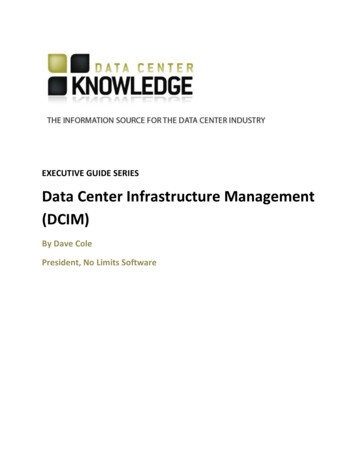
Example of Wire Basket Cable TraysFor Cabling Under Raised Floor24"1.375"RAISED FLOOR TILEDIVIDER18"9"5"4"FIBERCOPPERCABLINGSUPPORT STRUT36"12"18"5"4"FIBERCOPPERCABLINGSUPPORT STRUTOpen Area13.5"24"On CenterIEEE 802.3 HSSG1"1"
Overhead Cable Trays Less expensive than raised floor systemsCable trays can be attached to the top ofracks and cabinets (if they are uniform inheight)Cable trays suspended from the ceilingprovides more flexibility for supportingcabinets/racks of various heights and foradding and removing cabinets/racks.Cable trays can be installed with severallayersCoordinate location with lighting, ducts,overhead conduits, overhead powerIEEE 802.3 HSSGdistribution
Overhead Cable Tray Example3 Layer cable tray system: Bottom layer – signal Middle layer – power Top layer – fiber Signal Reference Grid inbrackets attached to lowerlayer of trays Fiber patch cables may bein fiber duct attached tothreaded rodsIEEE 802.3 HSSG
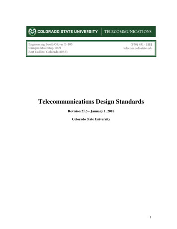
Infrastructure Administration Informative annex with TIA-606-A standardscompliant labeling scheme for allcomponents.Labeling scheme extended for use in datacentersCabinets and racks labeled by location usingtile grid or row/position identifiersAll cabinets, racks, patch panels, cables, andpatch cords should be labeledIEEE 802.3 HSSG
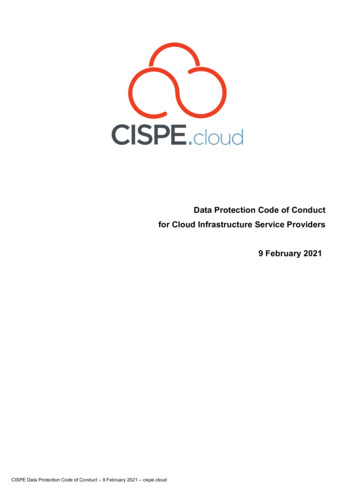
Labeling ExampleAAAB AC ADAEAFAG AHAIAJAK AL AM AN AO AP AQ AR ASATAU AV AW AX AY"X" COORDINATEAZ BABB BC BD0102Cat 6 x 24030405RIGHTFRONTCORNER0607CABINET AQ03CABINET AJ05080910111213"Y" COORDINATEPatch Panel for 24 Cat 6 from 1st Panel in Cab AJ05 to 2nd Panel in Cab AQ03AJ05-A to AQ03-B Ports 01-240102030405060708091011121314AIEEE 802.3 HSSG15161718192021222324A
Site Selection Informative annex with guidelines forselection of a site for a
IEEE 802.3 HSSG Data Center Standards ANSI/TIA-942 Telecommunications Infrastructure Standard for Data Centers Co-chairs: Chris DiMinico & Jonathan Jew Published 2005 – available through TIA at www.tiaonline.org ANSI/NECA/BICSI-002 Data Center Design and Implementation Best Practices co-chairs: Jonathan Jew & John Kacperski best practices – complements TIA-942 –