Transcription
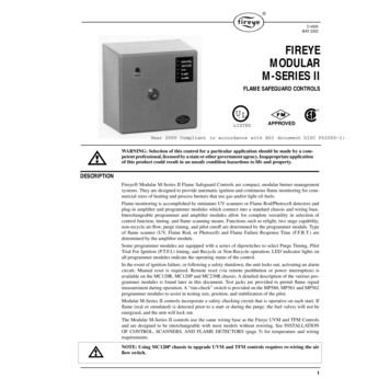
C-4000MAY 2002FIREYEMODULARM-SERIES IIFLAME SAFEGUARD CONTROLS UL LISTEDAPPROVEDYear 2000 Compliant in accordance with BSI document DISC PD2000-I:1998WARNING: Selection of this control for a particular application should be made by a competent professional, licensed by a state or other government agency. Inappropriate applicationof this product could result in an unsafe condition hazardous to life and property.DESCRIPTIONFireye Modular M-Series II Flame Safeguard Controls are compact, modular burner managementsystems. They are designed to provide automatic ignition and continuous flame monitoring for commercial sizes of heating and process burners that use gas and/or light oil fuels.Flame monitoring is accomplished by miniature UV scanners or Flame Rod/Photocell detectors andplug-in amplifier and programmer modules which connect into a standard chassis and wiring base.Interchangeable programmer and amplifier modules allow for complete versatility in selection ofcontrol function, timing, and flame scanning means. Functions such as relight, two stage capability,non-recycle air flow, purge timing, and pilot cutoff are determined by the programmer module. Typeof flame scanner (UV, Flame Rod, or Photocell) and Flame Failure Response Time (F.F.R.T.) aredetermined by the amplifier module.Some programmer modules are equipped with a series of dipswitches to select Purge Timing, PilotTrial For Ignition (P.T.F.I.) timing, and Recycle or Non-Recycle operation. LED indicator lights onall programmer modules indicate the operating status of the control.In the event of ignition failure, or following a safety shutdown, the unit locks out, activating an alarmcircuit. Manual reset is required. Remote reset (via remote pushbutton or power interruption) isavailable on the MC120R, MC120P and MC230R chassis. A detailed description of the various programmer modules is found later in this document. Test jacks are provided to permit flame signalmeasurement during operation. A “run-check” switch is provided on the MP560, MP561 and MP562programmer modules to assist in testing size, position, and stabilization of the pilot.Modular M-Series II controls incorporate a safety checking circuit that is operative on each start. Ifflame (real or simulated) is detected prior to a start or during the purge, the fuel valves will not beenergized, and the unit will lock out.The Modular M-Series II controls use the same wiring base as the Fireye UVM and TFM Controlsand are designed to be interchangeable with most models without rewiring. See INSTALLATIONOF CONTROL, SCANNERS, AND FLAME DETECTORS (page 5) for temperature and wiringrequirements.NOTE: Using MC120P chassis to upgrade UVM and TFM controls requires re-wiring the airflow switch.1
SPECIFICATIONSSupply:120V (min. 102, max. 132) 50/60 Hz. (MC120/MC120R/MC120P)230V (min. 196, max 253) 50/60Hz (MC230/MC230R)Table 1:AMBIENT TEMPERATURE LIMITSMINIMUMMAXIMUMControl125 F(52 C)- 40 F(- 40 C)Scanner UV1A,UV2, UV8A,45UV3200 F(93 C)- 40 F(- 40 C)Photocell 45CM1165 F(74 C)- 40 F(- 40 C)Flame Rod(Tip 2460 F)1500 F(816 C)- 40 F(- 40 C)Power Consumption:Shipping Weight (Approx.):Table 2:12 VA (Operating)3 lbs. (1.4kg)LOAD RATINGSFireye TerminalTypical LoadMaximum Rating & 120V 60 Hz3 or 4Individual or combinedPilot valve(s)Solenoid valveIgnition Transformer5Main Fuel Valve(s)125 VA pilot duty (solenoid) or25 VA pilot duty (solenoid) and400 VA (opening) motorized8Motor or contactorMotor normally energized and de-energized by theoperating control whose rating must be suitable. Terminal 8 rated to de-energize 9.8 FLA, 58.8 LRA, on safetylockout.AAlarm125 VA pilot duty (solenoid valve) plus250 VA (Transformer)50 VA, pilot dutyMinimum load requirement 100mAAPPROVALSUnderwriters Laboratories Inc.Listed Guide MCCZ - File MP 1537Factory Mutual System (FM) ApprovedUnderwriters Laboratories Inc.Recognized Components Guide MCCZ2File MP1537Canadian Standards AssociationGuide 300-1-0.2 Class 2642 Oil File LR7989Guide 140-A-2 Class 2632 Gas File LR7989American Gas Association (for the following models only):MC120MAUV1MP100, MP230 (Fixed), MP230H (Fixed), MP560 (Fixed)MAUV1TProgrammer modules where purge time, PTFI and recycle orMART1non-recycle operation is specified. See OrderingMART1TInformation— Programmer Modules.ANS Z21.20 Automatic Ignition Systems.Approvals do not apply to MC230 and MC230R Chassis and associated programmers.Year 2000 Compliant in accordance with BSI document DISC PD2000-I:1998.2
OUTLINE DIMENSIONSMOUNTING BASE3/16” DIA. MOUNTINGHOLES (4)S1KNOCKOUTS (12)FOR 1/2”CONDUIT7S232/N55 3/16A44611/25 3/165 5/162(50.8)41” DIA(25.4)36” FLEXIBLE CABLE (UV-1A-3)72” FLEXIBLE CABLE (UV-1A-6)1/2-14 STRAIGHTFEMALE PIPE THREADUV1A UV SCANNER1/21/2 X 14 ST.PIPETHREAD2 1/4”(57.2mm)1 1/2”(38.1mm)1 IN. DIA.(25.4mm)13/16 DIA.(206)2(50.8).700 DIA. FITTING (17.8mm)FOR WATER-TIGHT CONDUITSHIELDING OF 6 FT. (1830mm)LEADS IS REQUIRED3/8” PIPE THREAD36” (1m APPROX.)FLEXIBLE CABLEUV2 UV SCANNER1 3/16(30.2)UV8A SCANNER1 7/8 (47.6)1 1/4(31.8)13/16 HEX(20.6)15/16 HEX(23.8)2(50.8)TAPPED#6-32,2 HOLES1”(25.4)2 7/8”(73)2”(50.8)1/2(12.7)1 7/16(36.5)69ND1 FLAME RODTYPE 45CM1 PHOTOCELL SCANNERUV SCANNERType: 45UV3Model: 1050”L”2 3/8(60.3)1/2-14 NPT”L” LENGTH AS SPECIFIED: 12”, 18”, 24” (304.8, 457.2, 609.6)7/16(11.1)HOLE FOR3/4”SIGHTINGPIPE2 3/8(60.3)SCREW,1/4-20 THD3 1/4”(82)1 5/8”(41)3
ORDERING INFORMATIONCHASSIS (COMMON FOR ALL CONTROLS, INCLUDES DUST COVER):MC120MC120RMC120PMC230MC230R120 VAC Supply, 50 Hz/60 Hz120 VAC Supply, 50 Hz/60 Hz. Remote reset capability.120 VAC Supply, 50 Hz/60 Hz. Remote reset and post purge capability.230 VAC Supply, 50 Hz/60 Hz230 VAC Supply, 50 Hz/60Hz. Remote reset capability.PROGRAMMER MODULES:MP100, MP100EMP101MP102, MP102EMP230MP230HMP560MP561MP562Relight operation.Relight operation. Programmer will not lockout on flame signal during“off cycle.”Non-recycle on flame fail, 5 second PTFI.Selectable purge timing, trial for ignition timing, andrecycle/non-recycle operation.Selectable purge timing, trial for ignition timing, pilot stabilizing period,and recycle/non-recycle operation. For use with two stage burners.Selectable purge timing, pilot trial for ignition timing, pilot stabilizingperiod, and recycle/non-recycle operation. 10 second main flame trial forignition, run-check switch.MP560 programmer without pilot stabilization period.MP560 programmer with lockout on loss of air flow.Non-recycle operation only.NOTE: Programmers with the suffix "E" (e.g. MP100E) are for use with the MC230 and MC230Rchassis only.AMPLIFIER MODULES:USE WITH SCANNERS:MAUV1MAUV1TMART1MART1TUV amplifier, 2-4 second F.F.R.T.UV amplifier,.8 second F.F.R.T.Flame rectification amplifier,2-4 second F.F.R.T.Flame rectification amplifier,.8 second F.F.R.T.UV1A, UV2, UV8A, 45UV3-1050UV1A, UV2, UV8A, 45UV3-105045CM1, 69ND145CM1, 69ND1UV SCANNERS:UV1A3UV1A6UV2UV8A45UV3-10501/2” NPT connector, 3’ flex. cable1/2” NPT connector, 6’ flex. cable3/8” NPT connector, 3’ flex. cable1/2” NPT 90 degree angle head, 6’ flex. cable3/4” sleeve/setscrew mountFLAME 000K669ND1-1000K84Photocell with filterPhotocell without filter12 inch flame rod, 1/2” NPT connector18 inch flame rod, 1/2” NPT connector24 inch flame rod, 1/2” NPT connector
WIRING BASE (COMMON FOR ALL CONTROLS):61-3060Closed wiring base, surface mounting61-5042Open wiring base, cabinet mountingFor a complete system, choose one of each of the following:— Chassis— UV Scanner or Flame Detector— Programmer Module— Wiring Base— Amplifier ModuleWARNING: Installer must be trained and qualified. Follow the burner manufacturer’s instructions, if supplied. Otherwise, proceed as follows:INSTALLATION OF CONTROL, SCANNERS, AND FLAME DETECTORSWiring BaseMount the wiring base on the burner or on a panel. The location should be free from excessive vibration and within the specified ambient temperature rating. The base may be mounted in any angularposition.All wiring should comply with applicable electrical codes, regulations, and local ordinances. Usemoisture resistant wire suitable for at least 90 degrees C. Circuit recommendations are found onpages 26 through 30. Consult the factory for assistance with non-standard applications.WARNING: Controls require safety limits utilizing isolated mechanical contacts. Solid statelimit switches are not acceptable and should not be used due to their high leakage currents.Installing the Programmer and Amplifier ModulesWARNING: Remove power from the control before proceeding.AMPLIFIERPROGRAMMERSelect the appropriate programmer and amplifier modules for your application. Remove the dustcover from the chassis. Insert the amplifier module into the slot in the center of the chassis and gentlypush the module into position. Insert the programmer module into the slot at the right side of thechassis and gently push the module into position.NOTE: Refer to Programmer dipswitch settings on page 12 for the proper setting of the dipswitchesfor those programmers with this feature.WARNING: Turn off the power when installing or removing the control.5
Replaceable FuseThe programmer modules are designed with a field replaceable fuse. The fuse is located on theprinted circuit board below the cover. The fuse will blow as a result of an overload condition on Terminals 3, 4 or 5. To replace the fuse, remove power from the system. Remove the programmer module and using a small screwdriver or similar tool , remove the fuse from its holder. Install a Fireyereplacement fuse (P/N 23-176) or equivalent 8 amp fuse (e.g. Littlefuse 12AG, 8 amp, 125V). FORMP100E OR MP102E, ORDER FIREYE REPLACEMENT FUSE (P/N 23-183 OR EQUIVALENT3.5 AMP FUSE (E.G. LITTLEFUSE 2203.5, 3.5 AMP, 250V).WARNING: Remove power from the control before proceeding.INSTALLATION - UV SCANNERSWhere possible, obtain the burner manufacturer’s instructions for mounting the scanner. This information is available for most standard burners. The scanner mounting should comply with the following general instructions:1.2.3.Locate the scanner within 30 inches of the flame to be monitored, closer if possible.Select a scanner location that will remain within the ambient temperature limits of the UV-eyescanner (200 F/93 C). If cooling is required, use (a) an insulating coupling (Fireye P/N 35-69)to reduce conducted heat; (b) a window coupling (Fireye P/N 60-1257) to seal off furnace orburner pressure; (c) cooling air to reduce the scanner sight pipe temperature.Mount rigidly a short length (4″ to 8″) of 1/2″ or 3/4″ black iron pipe in a position that permits anunobstructed view of the pilot and/or main flame.CAUTION: The scanner must not sight the ignition spark directly, or any part of the burnerthat can reflect the spark back to the scanner.4.5.6.7.8.9.6The maximum UV signal from a flame is found in the first one-third of the visible flame takenfrom the point where the flame begins. The scanner sight pipe should be aimed at this area.A correct scanner application will not see a pilot flame that is too small to ignite the main flamereliably. Note particularly the test for minimum pilot that is described on page 22.On installations having negative pressure combustion chambers, a small hole (1/8″ or 3/16″)drilled in the sight pipe will assist in keeping the pipe clean and free from smoke.Two scanners may be installed on one burner if it is necessary to view two areas to obtain reliable detection of the flame. They should be wired in parallel.The UV-eye scanner is designed to seal off the sight pipe up to pressures of 1 PSI when the scanner lock nut is firmly tightened. Pressures in excess of 1 PSI should be blocked from the scanner.A quartz lens coupling (P/N 60-1290) or quartz window coupling (P/N 60-1257) may be used.Each is rated from -3 to 100 PSI max.To increase scanner sensitivity, a quartz lens coupling (P/N 60-1290) may be used. The quartzlens permits location of the UV-eye twice the distance noted in Item 1. Use 1/2″ x 1 1/2″ nipplebetween UV1A scanner and union. Use 3/8″ close nipple and 1/2″ by 3/8″ bushing on UV-2 applications.
General Requirements1.2.3.4.5.As close as possible — 30″ or closer.As cool as possible — Not over 200 F (93 C).Avoid sighting the spark — Resight scanner, shield between spark and scanner, or orifice toreduce reflected signal from spark.Must see pilot and/or main flame — Scanner view must be unobstructed,Minimum pilot test — See page 22.SCANNER MUST HAVE UNOBSTRUCTEDVIEW OF FLAMENOT THISNOT THISBUT THISFLAME MUST COMPLETELY COVERSIGHT OPENINGNOT THISNOT THISBUT THISTypical Scanner InstallationsDO NOT EXTEND MORE THANHALF-WAY INTO REFRACTORYThe maximum UV signalfrom a flame is found inthe first one-third of thevisible flame taken fromthe point where the flamebegins. The scanner sightpipe should be aimed atthis area.INSULATINGTUBINGSEALING UNIONSCANNERFORCEDAIREXTEND SIGHTING TUBE6”(1524) OR 8”(2032)METHODS OF COOLING SCANNERWiring of UV ScannersThe UV1A scanner is supplied with 36” or 72” of flexible cable. The UV-2 scanner is supplied with36” of flexible cable. If it is necessary to extend the scanner leads, the following instructions apply:1.2.3.Scanners without armored cable must be wired using metal cable or rigid conduit.High voltage wiring must not be installed in the same conduit with flame detector wiring.Selection of Scanner Wire:a. Use #14, 16, or 18 gauge wire with 90 C, 600 volt insulation for up to 200 feet of distance.(approx. 20% signal loss at 100 feet, 40% signal loss at 200 feet).b. Asbestos insulated wire should not be used.c. Multi-conductor cable is not recommended without prior factory approval.d. High voltage ignition wiring should not be installed in the same conduit with flame detectorwires.7
4.5.Installation of Extended Scanner Wiring:— For extended scanner wiring up to 500 feet, and for shorter lengths to reduce signal loss, usea shielded wire (Belden 8254-RG62 coaxial cable, or equal) for each scanner wire of UV1,UV2. The ends of the shielding must be taped and not grounded.Multiple Scanner Installations:— The wiring from multiple UV scanners may be installed in a common metallic conduit.— Multi-conductor cable is not recommended without prior factory approval.INSTALLATION - 45CM1 PHOTOCELL MOUNTThe 45CM1 photocell mount with #922 photocell and Rajah stud terminal, is designed for use in theblast tube on conventional atomizing oil burners. Two typical applications are shown below.BLAST TUBESCANNER TYPE 45CM1(COVER ON)BLAST TUBESCANNER TYPE 45CM1(COVER REMOVED)SHELLCOMBUSTIONHEADTest for Incandescent Refractory Hold-In with Photocell DetectorType 45CM1 Photocell Scanners are actuated by light energy. To assure that the flame failureresponse time is not extended by radiation from incandescent refractory, the following test is recommended.1.2.3.4.Operate the burner, following the burner manufacturer’s instructions, until the refractory is atmaximum operating temperature.Turn off the main fuel supply manually.Observe the display flame signal which must drop below 2 VDC within the flame failureresponse time (.8 seconds for MAUV1T, MART1T; 4 seconds for MAUV1, MART1).If the flame failure response time exceed 4 seconds, reduce the amount of light at the Photocellwith a screen, an orifice, or a filter lens, until the normal flame failure response is obtained.INSTALLATION - 69ND1 FLAME RODThe 69ND1 flame rod proves a gas pilot flame and/or main gas flame. It is a spark plug type unit consisting of 1/2″ NPT mount, a KANTHAL flame rod, a glazed porcelain insulating rod holder and aspark plug connector for making electrical connections. The 69ND1 is available in 12,″ 18″ or 24″lengths.The flame rod may be located to monitor only the gas pilot flame or both the gas pilot and main gasflames. It is mounted on a 1/2″ NPT coupling.The following instructions should be observed:1.2.3.4.8Keep flame rod as short as possible.Keep flame rod at least 1/2″ from any refractory.Flame rod should enter the pilot flame from the side so as to safely prove an adequate pilot flameunder all draft conditions.If the flame is nonluminous (air and gas mixed before burning), the electrode tip should extendat least 1/2″ into the flame, but not more than halfway through
WRONG POSITIONOF RODCORRECTPOSITIONOF RODINADEQUATE FLAMEPILOT BURNERCORRECT POSITIONOF PILOT FLAME5.6.7.If the flame is partly luminous, the electrode tip should extend only to the edge of the flame. It isnot necessary to maintain absolutely uninterrupted contact with the flame.It is preferable to angle the rod downward to minimize the effect of sagging and to prevent itfrom coming in contact with any object.An adequate grounding surface for the flame must be provided. The grounding surface in actualcontact with the flame must be at least four times greater than the area of the portion of the flamerod in contact with the flame. It is essential to adjust the flame rod and ground area ratio to provide a minimum signal reading of 6.0 VDC.Note: Interference from the ignition spark can alter the true signal reading by adding to, or subtracting from it. This trend sometimes may be reversed by interchanging the primary wires (line voltage)to the ignition transformer. This interference can also be reduced by the addition of grounded shielding between the flame rod and ignition spark.8.Proven types of flame grounding adapters, as shown below, may be used to provide adequategrounding surface. High temperature stainless steel should be used to minimize the effect ofmetal oxidation. This assembly may be welded directly over the pilot or main burner nozzleBOMB FINGROUNDINGASSEMBLYTHREADED RODASSEMBLYWIRING OF PHOTOCELLS AND FLAME RODSFor proper operation of flame rectification systems (photocells and flame rods), it is necessary tomaintain at least 20 megohms insulating resistance in the flame rectification circuit.1.2.The scanner should be wired using metal cable or rigid conduit.High voltage wiring must not be installed in the same conduit with scanner wiring.Selection of Scanner Wire1.2.Use #14, 16, or 18 gauge wire with 90 C, 600 volt insulation for up to 20 feet distance.The type of insulation used with flame rectification is important, since it must protect againstcurrent leakage resistance to ground. Use Belden 8254-RG62 Coaxial Cable (or equal) for runsgreater than 20 feet. Maximum wiring run not to exceed 100 feet.9
MAINTENANCEType UV1, UV2, UV8A, and 45UV3 Ultraviolet and 45CM1 Photoelectric ScannersThe viewing area of the scanner must be kept clean. Even a small amount of contamination willreduce the flame signal reaching the detector by a measurable amount. Wipe the viewing area routinely using a soft cloth dampened with concentrated detergent.Type 45CM1 Scanners include a replaceable #4-230 Phototube #922.Type 69ND1 Flame RodThe flame rod and its insulator should be kept clean by washing routinely with soap and water. Rodsshould be routinely replaced as they oxidize.Flame Signal StrengthRoutine observation of the flame signal strength will forewarn any deterioration in the capability ofthe flame detector or its application.Periodic Safety CheckIt is recommended that a procedure be established to test the complete flame safeguard system atleast once a month. This test should verify the proper operation of all limit switches and safety interlocks as well as flame failure protection and fuel safety shutoff valve tightness.RotationIt is recommended that control and scanner units purchased as spares be installed periodically.MC120P POST PURGE CHASSISThe MC120P Chassis provides the following capabilities:— A fifteen (15) second post purge at the end of an operating cycle or after a safety shutdowncondition (prior to initiating a lockout).— Remote reset in the event of a lockout condition.Fifteen (15) second post purge — The blower motor (terminal 8) remains energized for at least 15seconds at the end of every operating cycle (power removed from terminal 7). The b
Fireye Modular M-Series II Flame Safeguard Controls are compact, modular burner management systems. They are designed to provide automatic ignition and continuous flame monitoring for com-mercial sizes of heating