Transcription
Installation ManualPOWERCELL PDX Load Cell
Service XXLCongratulations on choosing the quality and precision of METTLER TOLEDO. Proper useaccording to these instructions and regular calibration and maintenance by our factorytrained service team ensure dependable and accurate operation to protect your investment.Contact us about a ServiceXXL agreement tailored to your needs and budget.We invite you to register your product atwww.mt.com/productregistrationso we can contact you about enhancements, updates and important notifications concerningyour METTLER TOLEDO contact.2 METTLER TOLEDOInstallation Manual POWERCELL PDX Load CellOrder number 6104407201/11
PrecautionsWARNINGREAD this manual BEFOREoperating or servicing thisequipment.PERMIT ONLY QUALIFIED PERSONNEL TO SERVICE THISEQUIPMENT. EXERCISE CARE WHEN MAKING CHECKS,TESTS, AND ADJUSTMENTS THAT MUST BE MADE WITHPOWER ON. FAILING TO OBSERVE THESE PRECAUTIONSCAN RESULT IN BODILY HARM.FOLLOW these instructionscarefully.WARNINGFOR CONTINUED PROTECTION AGAINST SHOCK HAZARD,CONNECT TO PROPERLY GROUNDED OUTLET ONLY. DONOT REMOVE THE GROUND PRONG.SAVE this manual for futurereference.ALWAYS DISCONNECT thisequipment from the powersource before cleaning orperforming maintenance.CALL METTLER TOLEDOfor parts, information, andservice.WARNINGDO NOT allow untrainedpersonnel to operate, clean,inspect, maintain, service,or tamper with this equipment.DISCONNECT ALL POWER TO THIS UNIT BEFORE INSTALLING,SERVICING, CLEANING, OR REMOVING THE FUSE. FAILURE TO DO SO COULD RESULT IN BODILY HARM AND/ORPROPERTY DAMAGE.WARNINGBEFORE CONNECTING/DISCONNECTING ANY INTERNAL ELECTRONIC COMPONENTSOR INTERCONNECTING WIRING BETWEEN ELECTRONIC EQUIPMENT, ALWAYSREMOVE POWER AND WAIT AT LEAST 30 SECONDS. FAILURE TO OBSERVE THESEPRECAUTIONS COULD RESULT IN BODILY HARM OR DAMAGE TO OR DESTRUCTIONOF THE EQUIPMENT.CAUTIONOBSERVE PRECAUTIONS FOR HANDLING ELECTROSTATICSENSITIVE DEVICES.01/11Order number 61044072 METTLER TOLEDOInstallation Manual POWERCELL PDX Load Cell3
Security AdvicesCAUTIONDANGER OF BODILY HARM OR PROPERTY DAMAGE! When a module is being moved, do not place your fingers or other bodyparts between the module and any other surface. If it is necessary to place your hands under a module during installation,make sure that the module is properly blocked so that it cannot move.CAUTIONFOR SAFTY REASONS DO NOT REPLACE MORE THAN ONE LOAD CELL AT A TIME.CAUTIONPOOR CONTACTS: Keep all electrical parts absolutely dry on the inside and as dry as possibleon the outside. If the cable ends will be exposed to the weather for a long period (notconnected to the load cell), apply dielectric compound, cover the cableends with plastic, and secure the open end with duct tape.CAUTIONRISK OF COMMUNICATION FAILURES DUE TO EXPOSED STRANDS OF WIRES Make sure that no stray conductors are left unsecured. Exposed strands ofwires can lead to communication failures if they bridge the connection inthe terminal block.Disposal of Electricaland Electronic EquipmentIn conformance with the European Directive 2002/96 EC on Waste Electrical and Electronic Equipment(WEEE) this device may not be disposed of in domestic waste. This also applies to countries outsidethe EU, per their specific requirements.Please dispose of this product in accordance with local regulations at the collecting point specified forelectrical and electronic equipment.If you have any questions, please contact the responsible authority or the distributor from which youpurchased this device.Should this device be passed on to other parties (for private or professional use), the content of thisregulation must also be related.Thank you for your contribution to environmental protection.4 METTLER TOLEDOInstallation Manual POWERCELL PDX Load CellOrder number 6104407201/11
Contents01/1111.1Introduction. 6General. 622.12.22.32.42.52.5Components. 7Introduction. 7Receiver Variant 1 “Standard”. 8Dimensions. 9Receiver Variant 2 “Retrofit”. 10Dimensions. 11Cables. tion. 13Foundation Requirements. 13Positioning Base Plates. 13Installing Locating Pins. 14Installing Lower Receivers. 14Installing Upper Receivers. 16Inserting Locating Tools. 16Installing Scale Modules. 17Removing Locating Tools. 18Installing Load Cells. 18Cabling. 20Shimming. 22Installation Summary. 2544.14.2Service Parts. 26Item Numbers. 26MTMS Part Numbers. 2855.1Specifications. 30General. 30Order number 61044072 METTLER TOLEDOInstallation Manual POWERCELL PDX Load Cell5
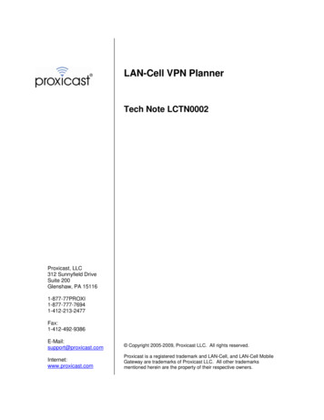
Introduction1Introduction1.1GeneralThe POWERCELL PDX load cell provides unequalled accuracy and reliability. This innovative load cell builds on the success of the industry-leadingPOWERCELL brand, which is operating reliably in every corner of the world.Its weighing performance is kept stable through “in-cell” measurement andcorrection of errors caused by weather, low voltage, and radio and telephoneinterference. The POWERCELL PDX load cell has the unique advantage ofproactively recognizing and reporting potential weighing errors and problemsbefore they lead to under-reported income, overload fines, and complaintsfrom customers or suppliers. By resisting lightning damage up to 80,000amperes, the load cell provides 24/7 operation and reduces your maintenance budget and unnecessary out-of-pocket expenses. Cables resist water,lightning, and rodents, and, if they are damaged, they can be replacedwithout recalibrating the scale.This manual explains the preferred procedure for installing POWERCELL PDXload cells in a scale.Figure 1-1: POWERCELL PDX Load Cell6 METTLER TOLEDOInstallation Manual POWERCELL PDX Load CellOrder number 6104407201/11
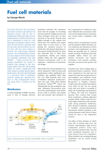
2Components2.1IntroductionAll POWERCELL PDX load cell components are made of high-quality materialand are designed and tested to function for a long time. They include thefollowing features: Rugged enclosure for protection from the environment (mud, stones,water, ice, etc.). Thick heavy-duty boots to prevent buildup of stones, dirt, snow, andice. Super heavy-duty cables to eliminate electromagnetic interference androdent damage. Cables can be replaced without recalibration. Larger load cell buttons to increase the service life. Two connectors for operation without junction boxes.Figure 2-1: POWERCELL PDX Load Cell ComponentsDepending on the region and related logistics, the components will arrivewithin the scale shipment or as a separate package.METTLER TOLEDO offers two types of receivers for the POWERCELL PDXload cell: Standard and Retrofit. The selection of components depends onthe receiver type.01/11Order number 61044072 METTLER TOLEDOInstallation Manual POWERCELL PDX Load Cell7
Components2.2Receiver Variant 1 “Standard”The “standard” receiver is a new design. It combines the strength of ourprevious receivers with easy installation and maintenance.This solution requires three threaded holes (M12 x 1.75) in the base platefor the locating pins. The force from the scale is introduced through the topsurface of the upper receiver. Shims can be added only under the lowerreceiver or under the base plate.2.2.1AssemblyUpper receiver with O-ringItem # 61043499POWERCELL PDX load cell(includes rubber boot)30 ton: Item # 4290488350 ton: Item # 42904891Rubber bootItem # 42904785Lower receiverItem # 61043498Shims1/4” (6 mm): Item # 610434891/8” (3 mm): Item # 610434901/16” (1.5 mm): Item # 61043491Locating pinsItem # 61043497Base plateBy othersFigure 2-2: Assembly for Receiver Variant 1 “Standard”8 METTLER TOLEDOInstallation Manual POWERCELL PDX Load CellOrder number 6104407201/11
2.2.2DimensionsTop receiver plate (cross section)The thickness of the top receiver platedepends on the scale design.Ø 69.85-mm hole required for receiver.Depth 13 mmLoad cell stack-up (cross section)Dimension without shims.Height from top surface of the base plateto the bottom surface of the top receiverplate 177.6 mm.Overall height 190.6 mmMaximum Ø 109.6 mm (load cell)Base plate (top view)Size and thickness depends on thefoundation design and stability.3 x M12x1.75 threaded holes requiredfor locating pins.Minimum depth 13 mm(120 separation)Figure 2-3: Dimensions for Receiver Variant 1 “Standard”01/11Order number 61044072 METTLER TOLEDOInstallation Manual POWERCELL PDX Load Cell9
Receiver Variant 2 “Retrofit”Components2.3The “retrofit” receivers are designed to make POWERCELL PDX load cellscompatible with scales that are built for use with POWERCELL 760 or MTXload cells (designs using a 69.85-mm-diameter hole). The receivers arenot compatible with other POWERCELL load cells that use smaller-diameterreceivers.This solution requires holes in the base plate for the lower receiver (Ø 69.85 mm)and a roll pin (Ø 12.7 mm). The force from the scale is introduced throughthe shoulders of both upper and lower receivers. Shims can be added underboth the upper and lower receivers, but not to exceed 9 mm at either receiver.If additional shimming is necessary, shim under the base plate(s).2.3.1AssemblyShims0.06” (1.5 mm): Item # 680003010.12” (3 mm): Item # 680005540.18” (4.5 mm): Item # 61024613Upper retrofit receiver with O-ringItem # 61043569POWERCELL PDX load cell(includes rubber boot)30 ton: Item # 4290488350 ton: Item # 42904891Rubber bootItem # 42904785Lower retrofit receiverItem # 61043571Shims0.06” (1.5 mm): Item # 680003010.12” (3 mm): Item # 680005540.18” (4.5 mm): Item # 61024613Locating pinItem # 72207803Base plateBy othersFigure 2-4: Assembly for Receiver Variant 2 “Retrofit”10 METTLER TOLEDOInstallation Manual POWERCELL PDX Load CellOrder number 6104407201/11
2.3.2DimensionsTop receiver plate (cross section)The thickness of the top receiver platedepends on the scale design.Ø 69.85-mm hole required for receiver.With chamfer 3.5 mm x 45 Minimum depth 25 mmLoad cell stack-up (cross section)Dimension without shims.Height from top surface of the base plate tothe bottom surface of the top receiver plate 207.9 mm.Overall height 251.5 mmMaximum Ø 109.6 mm (load cell)Base plate (top view)Size and thickness depends on the foundation design and stability.Ø 69.85-mm hole required for receiver.With chamfer 3.5 mm x 45 Minimum depth 25 mmØ 12.7-mm hole required for locating pin.Minimum depth 20 mm01/11Order number 61044072Figure 2-5: Dimensions for Receiver Variant 2 “Retrofit” METTLER TOLEDOInstallation Manual POWERCELL PDX Load Cell11
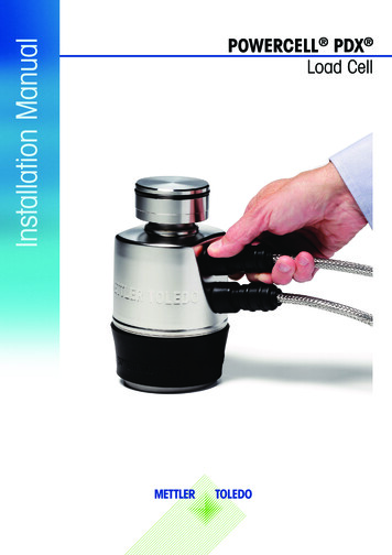
Components2.4CablesThe POWERCELL PDX network is designed to minimize cable length andpromote easy installation. No junction boxes are needed. POWERCELL PDXload cell cables are installed using quick-connect connectors, which producean audible “click” when installed properly. Because each POWERCELL PDXload cell has two interface ports, the host terminal can be connected to themost conveniently accessible load cell in the network, and the “daisy chain”starts at that load cell. Each load cell is cabled to the next, until the last loadcell in the network is connected. The cables can be connected to either porton the load cells. A termination connector and protective boot are secured tothe last port of the last load cell to complete the chain. Corrosion-resistant,glass-to-metal connectors ensure a good cell-to-cell connection and resistenvironmental elements. The METTLER TOLEDO IND780 terminal can support a network with as many as 24 nodes (with an auxiliary power supply).With the IND780 terminal, these load cells can be parsed into four logicallyindependent platforms.Always refer to drawing TC100884x when installing a POWERCELL PDXload cell system. The “x” in the drawing number is a place holder for therevision number. The latest copy of this drawing is available from METTLERTOLEDO.Home run cableTermination connectorCell-to-cell cablesFigure 2-6: POWERCELL PDX Load Cell NetworkNOTE: The cables that are required depend on the length and width of thescale and the position of conduits.Recommended and minimum bend radii for these cables:12 METTLER TOLEDO Recommended: 4” (10 cm). Minimum: 2” (5 cm).Installation Manual POWERCELL PDX Load CellOrder number 6104407201/11
3InstallationInstallation ProcedureMETTLER TOLEDO recommends the following procedure for installingPOWERCELL PDX load cells. Some installation steps can vary slightlydepending on the scale design. It is the technician’s responsibility to installthe load cells correctly.METTLER TOLEDO has achieved the best results by positioning the wholescale before anchoring the base plates to the foundation. That procedure,which requires using locating tools, is described in this chapter.A summary of the essential installation steps is provided at the end of thischapter.3.1Foundation RequirementsAll base plates for the load cells must be level and in the same plane foraccurate and repeatable weighing. Shims can be added under the receivers tolevel the scale. METTLER TOLEDO recommends that the top of the foundationat the base plate locations be level and in one plane (within 3 mm).Snap a chalk line on the foundation to mark the location of each side of thescale from approach coping to approach coping. 3.2These chalk lines will be used to align the modules as they are set inplace.Check the distance between the approach copings against thefoundation drawing to ensure that there is sufficient room for the scale.Check the diagonal measurements to ensure that the foundation issquare. If the foundation is not square, it could prevent you frominstalling the scale or cause weighing errors after the scale isinstalled. Refer foundation problems to the customer or customer’scontractor for correction.Positioning Base PlatesRoughly position the base plates on the foundation at the chalk lines. Referto the scale’s general layout drawing for the correct position of the load cellaxes.01/11Order number 61044072 METTLER TOLEDOInstallation Manual POWERCELL PDX Load Cell13
Installation3.3Installing Locating PinsVariant 1 “Standard”Install three locating pins (socket-head pins) in each base plate. Grease the threads of the pins with Loctite 242 threadlocker. Insert the M12x1.75 threaded ends into the base plate. Firmly tighten the pins with a 6-mm “Allen” or hex-head wrench.Variant 2 “Retrofit”Install a roll pin in each base plate. Insert the tapered end first. Tap the pin with a small hammer until it is completely vertical. Do not hammer the pin completely into/through the base plate holeuntil the receiver has been installed.Variant 1Variant 2Figure 3-1: Locating Pin Installation3.4Installing Lower ReceiversVariant 1 “Standard”Place one lower receiver on each base plate, aligning the holes with thelocating pins. Make sure there are no stones or debris between the receiver and baseplateVariant 2 “Retrofit”Use anti-seize compound to grease the lower receivers and insert one intoeach of the base plates, aligning the notch with the roll pin. Make sure that all receivers are snug in the base plate by visuallyinspecting for a gap. If you find a gap, place a piece of hard woodabove the receiver and gently hammer it until the receiver is seatedproperly.Figure 3-2: Lower Receiver (Variant 2)14 METTLER TOLEDOInstallation Manual POWERCELL PDX Load CellOrder number 6104407201/11
3.4.1Measuring and ShimmingShims are used to balance (or equalize) the scale mechanically, removingany inconsistencies in the level of the foundation or scale.Use a transit to check the elevation of the receiver at each base plate location. Make sure that all receivers are at the same height and the scale will notbe above or below the horizontal plane formed by the approaches. Tocheck this accurately, rest the measuring rod on the top surface of thereceiver at each base plate location. Use a spirit level to verify that all base plates are level in both planes. If the plates are not level, grind the concrete (below the base plate inthe locations where the plates are too high) and/or add shims until theplates are level in both directions. Do not exceed the following shimming thickness at the lower receivers:Variant 1 “standard” maximum 12 mm (bottom receiver only)Variant 2 “retrofit” maximum 18 mm (split between the top and bottom receivers)If you need to shim more than these amounts, shim between the baseplate and foundation.Notes: When shimming, always ensure that the top of the scale and the approachare in the same plane to 4 mm. The scale should be shimmed as closely as possible to the correct heightin order to achieve the best repeatability and accuracy. Shimming towithin 1 mm saves time during calibration because it ensures that thescale load is well distributed across all the load cells.01/11Order number 61044072 METTLER TOLEDOInstallation Manual POWERCELL PDX Load Cell15
Installation3.5Installing Upper ReceiversUse anti-seize compound to grease the upper (top) receivers and insert areceiver into each load cell receiver plate on the scale. The large O-ring on the receiver will hold it in place. Make sure thereceiver is inserted correctly by verifying that it is not tilted. The receiver should rest firmly on the receiver block. If it does not,make sure that it is not skewed and then gently tap the receiver intoplace with a block of wood and a hammer.3.6Inserting Locating ToolsMETTLER TOLEDO recommends using locating tools because this is the mostaccurate method of positioning the scale and base plates. It ensures thatthe load cells are positioned vertically and reduces installation time. Othermethods, such as adjusting by sight or by spirit level, generally deliver poorresults because they do not guarantee that the load cells will be correct inall axes.Variant 1 “Standard”Insert a locating tool into each lower receiver. Check for proper seating bylooking for a gap in the receiver shoulder and the base plate.Variant 2 “Retrofit”Insert a locating tool into each lower receiver, aligning the notch with thel
2 METTLER TOLEDO Installation Manual POWERCELL PDX Load Cell Order number 61044072 01/11 Service XXL Congratulations on choosing the quality and precision of METTLER TOLEDO. Proper use according to these instructions and regular calibration and maintenance by our factory-trained service team ensure depe