Transcription
Meru NetworksVIEW Certified ConfigurationGuideNovember 2011 1725-36067-001 Rev. G
View Certified Configuration Guide: Meru NetworksTrademark InformationPOLYCOM , the Polycom “Triangles” logo and the names and marks associated with Polycom’s products aretrademarks and/or service marks of Polycom, Inc. and are registered and/or common law marks in the United Statesand various other countries. All other trademarks are property of their respective owners. No portion hereof may bereproduced or transmitted in any form or by any means, for any purpose other than the recipient’s personal use,without the express written permission of Polycom.Patent InformationThe accompanying product is protected by one or more U.S. and foreign patents and/or pending patent applicationsheld by Polycom, Inc.DisclaimerSome countries, states, or provinces do not allow the exclusion or limitation of implied warranties or the limitation ofincidental or consequential damages for certain products supplied to consumers or the limitation of liability forpersonal injury, so the above limitations and exclusions may be limited in their application to you. When the impliedwarranties are not allowed to be excluded in their entirety, they will be limited to the duration of the applicable writtenwarranty. This warranty gives you specific legal rights which may vary depending on local law.Copyright NoticePortions of the software contained in this product are:Copyright 1998, 1999, 2000 Thai Open Source Software Center Ltd. and Clark CooperCopyright 1998 by the Massachusetts Institute of TechnologyCopyright 1998-2008 The OpenSSL ProjectCopyright 1995-1998 Eric Young (eay@cryptsoft.com). All rights reservedCopyright 1995-2002 Jean-Loup Gailly and Mark AdlerCopyright 1996-2008, Daniel Stenberg, daniel@haxx.se Permission is hereby granted, free of charge, to any person obtaining a copy of this software and associateddocumentation files (the “Software”), to deal in the Software without restriction, including without limitation the rightsto use, copy, modify, merge, publish, distribute, sublicense, and/or sell copies of the Software, and to permit personsto whom the Software is furnished to do so, subject to the following conditions:The above copyright notice and this permission notice shall be included in all copies or substantial portions of theSoftware.THE SOFTWARE IS PROVIDED “AS IS”, WITHOUT WARRANTY OF ANY KIND, EXPRESS OR IMPLIED,INCLUDING BUT NOT LIMITED TO THE WARRANTIES OF MERCHANTABILITY, FITNESS FOR A PARTICULARPURPOSE AND NONINFRINGEMENT. IN NO EVENT SHALL THE AUTHORS OR COPYRIGHT HOLDERS BELIABLE FOR ANY CLAIM, DAMAGES OR OTHER LIABILITY, WHETHER IN AN ACTION OF CONTRACT, TORTOR OTHERWISE, ARISING FROM, OUT OF OR IN CONNECTION WITH THE SOFTWARE OR THE USE OROTHER DEALINGS IN THE SOFTWARE. 2011 Polycom, Inc. All rights reserved. Polycom, Inc.4750 Willow RoadPleasanton, CA 94588-2708USANo part of this document may be reproduced or transmitted in any form or by any means, electronic or mechanical,for any purpose, without the express written permission of Polycom, Inc. Under the law, reproducing includestranslating into another language or format.As between the parties, Polycom, Inc., retains title to and ownership of all proprietary rights with respect to thesoftware contained within its products. The software is protected by United States copyright laws and internationaltreaty provision. Therefore, you must treat the software like any other copyrighted material (e.g., a book or soundrecording).Every effort has been made to ensure that the information in this manual is accurate. Polycom, Inc., is notresponsible for printing or clerical errors. Information in this document is subject to change without notice.ii
ContentsContents . 3Introduction . 1Certified Product Summary.1Known Limitations .2Polycom References .3Product Support .3Network Topology .4Chapter 1: Initial Setup for Meru Wireless Infrastructure . 5Configuring a New Controller Starting from Factory Defaults .5Installing Software .8Chapter 2: Configuration Guidelines . 9Configure VLAN .9Configure Radius Profile .10Configure Security Profile .11Configure ESS Profile .15Radio Interface Configuration .17Chapter 3: TSPEC Configuration . 21Define and Upload a Boot Script to Enable WMM Access.21Useful AP Level TSPEC Commands.22Script File Modification.23iii
VIEW Configuration Guide: Meru Networks
IntroductionPolycom's Voice Interoperability for Enterprise Wireless (VIEW) Certification Program is designed toensure interoperability and high performance between Polycom Wireless Telephones and WLANinfrastructure products.The products listed below have been thoroughly tested in Polycom’s lab and have passed the VIEWCertification Test Plan. This document details how to configure Meru Networks Wireless LAN Systemand AP3xx with Polycom Wireless Telephones.Certified Product SummaryTable 1Manufacturer:Meru Networks: www.merunetworks.comCertified MC1500MC10001AP Radio(s):2.4 GHz (802.11b/g/n), 5 GHz (802.11a/n)Security:None, WPA-PSK, WPA2-PSK, WPA2-PEAP with OKCQoS:Wi-Fi StandardAP software version certified:4.0-SR5-5Network topology:Switched Ethernet (recommended)1Denotes products directly used in VIEW Certification1
VIEW Configuration Guide: Meru NetworksTable 2SpectraLink 8400 Series test parameters1Handset radio mode:Meets VIEW minimum call capacity per AP:802.11b6 calls802.11b/g10 calls802.11bgn8 calls802.11a & 802.11an10 calls22221SpectraLink handset models and their OEM derivatives are verified compatible with the WLAN hardware andsoftware identified in the table. Throughout the remainder of this document they will be referred to collectivelyas “SpectraLink Wireless Telephones”, “phones” or “handsets”.2Maximum calls tested during VIEW Certification. The certified product may actually support a higher number ofmaximum calls for 802.11a and 802.11g radio modes.Table 3SpectraLink 8020/8030 test parameters12Handset radio modeMeets VIEW minimum call capacity per AP802.11b & b/g mixed & gn6 (Wi-Fi Standard QoS)2802.11a and 802.11an8 (Wi-Fi Standard QoS)21SpectraLink handset models and their OEM derivatives are verified compatible with the WLAN hardware andsoftware identified in the table. Throughout the remainder of this document they will be referred to collectivelyas “SpectraLink Wireless Telephones”, “phones” or “handsets”.2Maximum calls tested during VIEW Certification. The certified product may actually support a higher number ofmaximum calls for 802.11a and 802.11g radio modes.
IntroductionKnown Limitations There should be a one-on-one mapping to ESSID and VLAN.If not, Multicast will not work EAP-FAST is not supported Only Virtual Cell/Virtual Port and the tunneled dataplane mode were tested. It is not knownhow well a layered deployment or bridged dataplane mode would perform.Polycom ReferencesPlease refer to the Polycom Deploying Enterprise-Grade Wi-Fi Telephony white papers which areavailable athttp://www.polycom.com/products/voice/wireless solutions/wifi communications/handsets/SpectraLink 8020 wireless.html -spectralink-8400.pdfThis document covers the security, coverage, capacity and QoS considerations necessary for ensuringexcellent voice quality with enterprise Wi-Fi networks.For more detailed information on wireless LAN layout, network infrastructure, QoS, security andsubnets, please see the Best Practices Guide to Network Design Considerations for SpectraLink WirelessTelephones, which is available t/us/support/voice/wi-fi/index.html.This document identifies issues and solutions based on Polycom’s extensive experience in enterpriseclass Wi-Fi telephony. It provides recommendations for ensuring that a network environment isadequately optimized for use with SpectraLink Wireless Telephones.Product SupportInstallation and configuration guides for Meru Wireless LAN Controllers and Access Points can be foundon the Meru Networks website at http://www.merunetworks.com.3
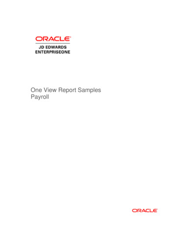
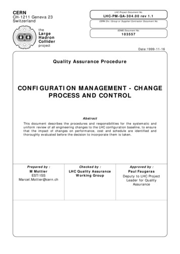
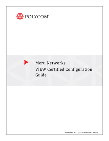
VIEW Configuration Guide: Meru NetworksNetwork TopologyThe following topology was used during VIEW Certification testing:4
Chapter 1: Initial Setup for Meru WirelessInfrastructureThe Meru network enterprise LAN solution is a controller-based solution. The controller should beinitially configured before setting up the Access Points and its parameters for deploying and servicingthe wireless clientsConfiguring a New Controller Starting from FactoryDefaultsInitial setup of a controller requires a serial connection to a PC or laptop to configure the controllernetwork identification settings. After that, the controller management interface is accessed through thenetwork via an SSH2 connection for using the CLI or secure HTTP connection from the Web UI.Startup1 Before applying power to the controller, make sure the controller is connected to an Ethernetswitch.2 Set up a serial connection from the PC or laptop to the controller. For the initial controllerconfiguration, you must connect to the controller using the serial port. Plug the Null modem serialcable into the controller serial port and the other end into the serial port of the PC or laptop.3 On the PC or laptop, set up an ANSI or VT100 compatible terminal session with the followingsettings:115200 baud8 bitsno parity1 stop bitno flow control4 Plug the controller into the AC power source.5 Press the controller Power On/Off switch. When the controller boots for the first time, it shows aseries of informational messages and then presents the default login prompt.6 Log in as admin using the default password, also admin:default login: adminPassword:5
VIEW Configuration Guide: Meru NetworksEnter parameters1 Run setup, the initial configuration script:default# setupBegin system configuration .Country code configuration for this machine.The country code is currently set to USWould you like to change it [yes/no/quit]?2 Type the hostname for the controller (the hostname must be less than 32 characters, cannot startwith integers, or contain all integers). In the following example, we choose the hostnamecontroller for our controller:Please enter host name, or q to quit: controllerIs controller correct [yes/no/quit]?: yIP Configuration for this machine.3 Change the default admin password to prevent any security breaches:Currently default password is used for adminWould you like to change the password [yes/no/quit]?: yesChanging password for user admin.New password:Retype new password:passwd: all authentication tokens updated successfully.4 Configure IP addressing for the controllerAt this stage, we will assign a static IP address and a netmask to the controller, as well as agateway address, so a telnet or browser connection can be made. (If your controller and APs areon different subnets, you can assign DHCP addressing for the controller now or later with the CLIor Web Interface.)Would you like to configure networking? yWould you like to use Dynamic IP configuration (DHCP)[yes/no/quit]: nPlease enter the IP configuration for this machine.Each item should be entered as an IP version 4 style address in dotted-decimal notation (forexample, 10.20.30.40)Enter IP address, or q to quit: nnn.nnn.nnn.nnnIs nnn.nnn.nnn.nnn correct [yes/no/quit]? yEnter netmask, or q to quit: nnn.nnn.nnn.nnnIs nnn.nnn.nnn.nnn correct [yes/no/quit]? yEnter default gateway (IP), or q to quit: nnn.nnn.nnn.nnnIs nnn.nnn.nnn.nnn correct [yes/no/quit]? Y5 For the initial start-up, if your controller is to be on a different subnet from the APs (Layer 3configuration), enter the appropriate DNS server information for your WLAN.6
Chapter 1: Initial Setup for Meru Wireless InfrastructureWould you like to configure a Domain Name Server [yes/no/quit]? yDomain Name Server (DNS) configuration for this machine.Enter one or more DNS name servers.For this prompt only use q when finished entering name servers.Enter Name Server IP Address, or q to quit: controller#nnn.nnn.nnn.nnn6 If desired, change the controller’s index number. If you select Yes, you will be prompted to set thedesired number, which can be any integer from 0-31. If you select No, the controller’s index willremain at the default (0).7 You are now prompted to set the time zone. You can set it now or later, using the timezonecommand.Synchronize the system time with a Network Time Protocol server so that the controller time isextremely accurate, or set the time from the CLI with the calendar set command.Synchronize time with a Network Time Protocol (NTP) server[yes/no/quit]?: nYou can use the "calendar set" option of the cli to set the time8 The system asks for permission to reboot. Tell it to reboot, when prompted:System Configuration completed.Do you want to commit your changes and reboot? [yes/no/quit] yesBroadcast message from root (Wed Aug 17 11:30:32 2005):Now rebooting system.The system is going down for reboot NOW!The controller restarts. The full restart process can take up to 5 minutes.Verification1 Once the server has completely booted up, verify that you can connect to the controller using theWeb UI or the CLI. To start the Web UI, open a browser window and provide the IP address of the Controller youhave just configured (http://nnn.nnn.nnn.nnn). Note that you may need to accept a securitycertificate and/or confirm a security exception before accessing the interface. This can varydepending on the Internet browser in use. To use the CLI, start a SSH2 session using the IP address of the controller.2 Verify that each access point receives power. If the access point is receiving power, the power LEDglows green.Now the network is ready for configuration7
VIEW Configuration Guide: Meru NetworksInstalling SoftwareThe following section describes step by step details on how to load the controller with the requiredSystem Director release to support Polycom phones. The certified System Director version is 4.0-SR5.1 Upload the new controller image from the FTP server (where xxxx is based on the model of theWLAN controller).controller# copy ftp://ftpuser:ftppasswd@offbox-ip-address/ meru4.0.SR5-xxxx.tar space .To check for successful ftp upload, type:controller# sh flashThe filename meru-4.0.SR5-xxxx.tar should be present in the listing.2 Upgrade the controller with the following command. The controller version must be 3.6.1-X orlater before the upgrade.controller# upgrade controller 4.0.SR5-53 Plug the access points into the layer 2 or layer 3 switch.4 Access Points can obtain their power from 802.3af standard Power over Ethernet (PoE). Thepower can be supplied by a PoE-compatible network switch or PoE power injector installedbetween the switch and the AP.8
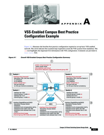
Chapter 2: Configuration GuidelinesDuring configuration of the Meru system, different parameters are configured as described in thefollowing sections: Configure VLAN Configure a Security Profile Configure an ESS ProfileConfigure VLANIt is recommended to separate the voice and data traffic onto different VLAN’s. An exampleconfiguration for a Polycom only VLAN follows. VLANs for other devices should be configured to providethe necessary separation.Configuration can be done using the GUI or the CLI. Connect to the Meru CLI either by using a serialcable connected to the serial port of the controller or by connecting via Secure Shell using a tool likeSecure CRT or HyperTerminal.CLI Stepscontroller# configure terminalcontroller (config)#vlan polycom tag nnncontroller (config-vlan)# interface FastEthernet1(This represents the index of the port on the front of the controller.)controller (config-vlan)# ip address nnn.nnn.nnn.nnncontroller (config-vlan)# ip default-gateway nnn.nnn.nnn.nnncontroller (config-vlan)# ip dhcp-server nnn.nnn.nnn.nnncontroller (config-vlan)# ip dhcp-passthroughcontroller (config-vlan)# no ip dhcp-overridecontroller (config-vlan)# exitGUI Steps1 Navigate to System Config- Quick Start and click on the VLAN tab.2 Click on Add.3 Enter the VLAN Name, Tag, Fast Ethernet Interface Index (the index of the port on the front of thecontroller), IP Address, Netmask, IP Address of the Default Gateway, and DHCP Server IP Address.9
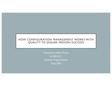
VIEW Configuration Guide: Meru Networks4 Set Override DHCP Server Flag to Off. (The address entered when initially provisioning thecontroller will be used for the DHCP server.)5 Set DHCP Relay Pass-through to On. (The DHCP requests will be sent through unchanged.)6 Click on OK.Configure Radius ProfileMeru supports the use of a Radius server to provide WPA2-Enterprise PEAP security.GUI Steps1 Navigate to System Config- Quick Start and click on the Radius profile tab.2 Click on Add.3 Enter the RADIUS Profile Name, Description, RADIUS IP, RADIUS Secret, and RADIUS Port.4 Leave the MAC Address Delimiter set to the default of Hyphen (-) and the Password Type to thedefault of Shared Key.5 Click on OK.10
Chapter 2: Configuration GuidelinesCLI Stepscontroller# configure terminalcontroller(config-radius)# radius-profile VIEWcontroller(config-radius)# description VIEWcontroller(config-radius)# ip-address nnn.nnn.nnn.nnncontroller(config-radius)# key aaasharedsecretcontroller(config-radius)# port 1812(The default port is usually the correct one, so this entry is probably unnecessary.)controller(config-radius)# exitcontroller# exitConfigure Security ProfileMeru supports the following 802.11 security mechanisms for the Polycom phones: Open (will not work with the phones in n-enabled radio modes) WPA-PSK WPA2-PSK WPA2-PEAP11
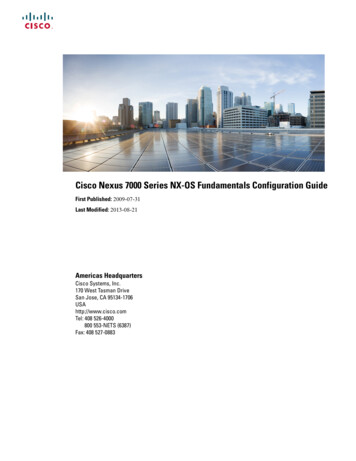
VIEW Configuration Guide: Meru NetworksThe Meru WLAN System supports n security on radios that are not n-enabled. It is often useful for initialprovisioning. A security profile with the name of default is automatically created on each VLAN.The Meru WLAN System supports WPA-PSK mode with Polycom Wireless Telephones and can beconfigured as follows. Note that the pre-shared key (PSK) in the controller can be entered inhexadecimal or ASCII formats. If it is entered in hexadecimal, it must be preceded with 0x.CLI Stepscontroller# configure terminalcontroller(config-security)# security-profile wpapasscontroller(config-security)# allowed-l2-modes wpa-pskcontroller(config-security)# encryption-modes tkipcontroller(config-security)# psk key merupolycomcontroller(config-security)# exitcontroller# exitGUI Steps1 Navigate to System Config- Quick Start and click on the Security Profile tab.2 Click on Add.3 Enter the Security Profile Name and the Pre-shared Key (Alphanumeric/Hexadecimal).4 Check the radio button WPAPSK.5 Click on OK.12
Chapter 2: Configuration GuidelinesThe Meru WLAN System supports WPA2-PSK mode with Polycom Wireless Telephones and is configuredas follows. Note that the pre-shared key (PSK) in the controller is entered in hexadecimal or ASCIIformats. If it is entered in hexadecimal, it must be preceded with 0x.CLI Stepscontroller# configure terminalcontroller(config-security)# security-profile wpa2passcontroller(config-security)# allowed-l2-modes wpa2-pskcontroller(config-security)# encryption-modes ccmpcontroller(config-security)# psk key merupolycomcontroller(config-security)# exitcontroller# exitGUI Steps1 Navigate to System Config- Quick Start and click on the Security Profile tab.2 Click on Add.3 Enter the Security Profile Name and the Pre-shared Key (Alphanumeric/Hexadecimal).4 Check the radio button WPA2PSK.5 Click on OK.13
VIEW Configuration Guide: Meru NetworksThe Polycom phones support EAP-PEAPv0/MSCHAPv2. The Meru WLAN controller system is configuredas follows.CLI Stepscontroller# configure terminalcontroller(config-security)# security-profile wpapeapcontroller(config-security)# allowed-l2-modes wpa2controller(config-security)# encryption-modes ccmpcontroller(config-security)# exitcontroller# exitGUI Steps1 Navigate to System Config- Quick Start and click on the Security Profile tab.2 Click on Add.3 Select the previously created RADIUS profile from the Primary RADIUS Profile Name dropdownlist.4 Check the radio buttons WPA2 and CCMP-AES.5 Click on OK.14
Chapter 2: Configuration GuidelinesConfigure ESS ProfileThe ESSID for Polycom Wireless Telephones should be configured as follows. Note: When enabling themulticast support (for the server discovery and PTT feature) there must be only one ESSID per VLAN;otherwise multicast traffic is not passed. The Meru WLAN system supports WMM and SIP. There are noadditional QoS rules that need to configure for the phones. Please Note – one should enable the UAPSDfeature in the ESS profile. These are switched off by default.CLI Stepscontroller# configure terminalcontroller(config-essid)# essid polycomcontroller(config-essid)# multicast-enablecontroller(config-essid)# virtual-portcontroller(config-essid)# ofile wpa2passcontroller(config-essid)# dataplanetunneledcontroller(config-essid)# tunnel-type configured-vlan-onlycontroller(config-essid)# vlan name polycomcontroller(config-essid)# ssid viewcontroller(config-essid)#wmm-support15
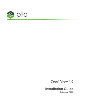
VIEW Configuration Guide: Meru oller(config-essid)# beacon dtim-period 1controller(config-essid)# beacon period100controller(config-essid)# exitcontroller(config)#exitGUI Steps1 Navigate to System Config- Quick Start and click on the ESS Profile tab.2 Click on Add.3 Set Virtual Cell, Virtual Port, WMM Support, and APSD Support to On.4 Set the Tunnel Interface Type to Configured VLAN Only and the VLAN Name to the VLAN namedefined above (polycom).5 Set the DTIM Period to 1.6 Click on OK.16
Chapter 2: Configuration GuidelinesRadio Interface ConfigurationThe Polycom Wireless Telephones can utilize 802.11a, 802.11b, 802.11g, 802.11bg, 802.11an, or802.11bgn modes. Additionally, it is recommended to configure the interface for Short Preamble mode.The AP320s interface 1 supports 802.11b, 802.11g, 802.11bg, and 802.11bgn modes, while interface 2supports 802.11a and 802.11an modes for the phones.The following commands are used in order to configure the interface of an AP. In this example, accesspoint 5 is configured for 802.11g operation with Short Preamble and channel width to be 20 MHz.CLI Stepscontroller#configure terminalcontroller(config-if-802)# interface Dot11Radio 5 1controller(config-if-802)# rf-mode 802.11gcontroller(config-if-802)# preamble-shortcontroller(config-if-802)# channel 1controller(config-if-802)# channel-width 20-mhzcontroller(config-if-802)# exitcontroller#exitGUI Steps1 Navigate to Configuration- Wireless- Radio.2 Select the desired radio interface of the connected AP.3 Select the band from the RF Band Selection dropdown list.4 Select the Channel Width.5 Set Short Preamble to Off.6 Click on OK.17
VIEW Configuration Guide: Meru NetworksCLI StepsFollowing is a similar example of configuration for 802.11a operation with the Polycom 8020/8030Wireless Telephones where we configure access point 5 for channel 36 on 802.11a and channel widthconfiguration to be 40 MHz with extension channel to be the one above.controller#configure terminalcontroller(config-if-802)# interface Dot11Radio 5 2controller(config-if-802)# rf-mode 802.11acontroller(config-if-802)# channel 36controller(config-if-802)# channel-width -802)# exitcontroller# exitGUI Steps1 Navigate to Configuration- Wireless- Radio.2 Select the desired radio interface of the connected AP.3 Select the band from the RF Band Selection dropdown list.4 Select the Channel Width.18
Chapter 2: Configuration Guidelines5 Click on OK.Note: Additional details on RF deploymentFor additional details on RF deployment please see the Deploying Enterprise-Grade Wi-FiTelephony white paper and the Best Practices Guide for Deploying Polycom 8020/8030 WirelessTelephones or Best Practices for Deploying Polycom SpectraLink 8400 Series Handsets. It isalways practice to deploy the APs with an overlapping coverage of at least -60 dBm across theinfrastructure for an effective voice solution.19
VIEW Configuration Guide: Meru Networks20
Chapter 3: TSPEC ConfigurationIn version 4.0-SR5, TSPEC is not enabled by default in the Meru Infrastructure. TSPEC parameters areenabled by using a boot script. There are no additional commands that are needed to enable TSPEC.Define and Upload a Boot Script to Enable WMM AccessAn additional script, tspec.scr, is required in order to enable the TSPEC parameters. The script is runeach time the AP’s are booted. This script enables TSPEC and other settings to enhance voice quality ofservice and set the maximum voice call limit. By default the maximum calls is set to 8 for the 2.4 GHzband and 10 for the 5 GHz band.The bootscript tspec.scr must be downloaded from the Meru Networks support portal.In the boot script 2 radios will be involved. Radio0 is the 2.4 GHz radio and Radio1 is the 5 GHz radio. Bydefault radio01 and radio11 are used in some of the commands in the boot script. These are virtualradio numbers assigned due to the definition of the SSID. These can change depending on the numberof SSID's defined on the controller. Thus, the bootscript must be edited if the SSID is not the only onedefined.Note: Checking the bootscriptThe bootscript must be checked for the need for editing and a system reload whenever newSSID’s are defined.Note: Loading the bootscriptThe bootscript must be loaded even if access control is not used as it provides importantperformance tuning.1 To determine the virtual radio number, perform the following:2 Ensure that both radios are online and enabled for an AP using the information from “ConfigureRadios”. Note the AP number.3 Connect using the CLI as described in “Configuring a New Controller Starting from FactoryDefaults”.4 Type connect ap n, where n is the AP number noted in step 1. The result will look like thefollowing:ap 6 vap display21
VIEW Configuration Guide: Meru NetworksDeviceBSSIDState Assc PwrS Essid------------------------- ----- ---- ---- 0c:e6:c1:24:43RUN00viewradio01-1 06:06:01:07:21:3dRUN11viewradio11-1 06:2c:01:0c:d6:0cRUN11viewThe virtual radios are read from the first and second line of the Device column. In this example,they are “radio01” and “radio11”.5 Edit the boot script (tspec.scr) available from the Meru support portal, replacing every use ofradio01 and radio11 in the script with the virtual radio identifies found.6 Copy the script into the controller using the following:controller# cd ATS/scriptscontroller# copy r.controller# configure terminalcontroller (config)# boot-script tspec.scrcontroller (config)# endThis script will set the TSPEC parameters during initialization of all the Access Points during bootup. Once the script is set up the APs will come up with TSPEC parameters all enabled.Useful AP Level TSPEC CommandsAP level commands are used to monitor TSPEC related functionalities. The number of supported phonecalls per AP is changed using the CLI. TSPEC commands will be integrated into the controller CLI and GUIin future releases.To use these commands, connect to the CLI using the method described in “Configuring a NewController Starting from Factory Defaults”.controller# connect ap nap n radio tspec radio0/1 show(This shows the details of the bandwidth allocated for different phones. It also shows if TSPEC isenabled by looking at highest available Access Category Mandatory (acm) queue. If highest acm is 1TSPEC is disabled. Otherwise, it is enabled. radio0 indicates the 2.4 GHz radio and radio1 indicates the 5GHz radio.)ap n radio tspec radio0/1 weightage 10 10 10 70(This command changes the bandwidth allocation for different access categories. Starting from the left,the values
VIEW Configuration Guide: Meru Networks 2 Table 2 SpectraLink 8400 Series test parameters Handset1 radio mode: Meets VIEW minimum call capacity per AP: 802.11b 6 calls2 802.11b/g 10 calls2 802.11bgn 8 calls2 802.11a & 802.11an 10 calls2 1 SpectraLink handset models and their OEM derivatives are verified compatible with the WLAN hardware and .