Transcription
DL06 IBox InstructionsPLC User Manual SupplementManual Number: DL06-IBOX-S
WARNINGThank you for purchasing automation equipment from Automationdirect.com , doing business asAutomationDirect. We want your new automation equipment to operate safely. Anyone who installs oruses this equipment should read this publication (and any other relevant publications) before installing oroperating the equipment.To minimize the risk of potential safety problems, you should follow all applicable local and nationalcodes that regulate the installation and operation of your equipment. These codes vary from area to areaand usually change with time. It is your responsibility to determine which codes should be followed, andto verify that the equipment, installation, and operation is in compliance with the latest revision of thesecodes.At a minimum, you should follow all applicable sections of the National Fire Code, National ElectricalCode, and the codes of the National Electrical Manufacturer's Association (NEMA). There may be localregulatory or government offices that can also help determine which codes and standards are necessaryfor safe installation and operation.Equipment damage or serious injury to personnel can result from the failure to follow all applicable codesand standards. We do not guarantee the products described in this publication are suitable for yourparticular application, nor do we assume any responsibility for your product design, installation, oroperation.Our products are not fault-tolerant and are not designed, manufactured or intended for use or resale ason-line control equipment in hazardous environments requiring fail-safe performance, such as in theoperation of nuclear facilities, aircraft navigation or communication systems, air traffic control, direct lifesupport machines, or weapons systems, in which the failure of the product could lead directly to death,personal injury, or severe physical or environmental damage ("High Risk Activities"). AutomationDirectspecifically disclaims any expressed or implied warranty of fitness for High Risk Activities.For additional warranty and safety information, see the Terms and Conditions section of our catalog. Ifyou have any questions concerning the installation or operation of this equipment, or if you needadditional information, please call us at 770-844-4200.This publication is based on information that was available at the time it was printed. AtAutomationDirect we constantly strive to improve our products and services, so we reserve the right tomake changes to the products and/or publications at any time without notice and without anyobligation. This publication may also discuss features that may not be available in certain revisions of theproduct.TrademarksThis publication may contain references to products produced and/or offered by other companies. Theproduct and company names may be trademarked and are the sole property of their respective owners.AutomationDirect disclaims any proprietary interest in the marks and names of others.Copyright 2006, Automationdirect.com IncorporatedAll Rights ReservedNo part of this manual shall be copied, reproduced, or transmitted in any way without the prior, writtenconsent of Automationdirect.com Incorporated. AutomationDirect retains the exclusive rights to allinformation included in this document.
AVERTISSEMENTNous vous remercions d'avoir acheté l'équipement d'automatisation de Automationdirect.com , en faisant desaffaires comme AutomationDirect. Nous tenons à ce que votre nouvel équipement d'automatisation fonctionne entoute sécurité. Toute personne qui installe ou utilise cet équipement doit lire la présente publication (et toutes lesautres publications pertinentes) avant de l'installer ou de l'utiliser.Afin de réduire au minimum le risque d'éventuels problèmes de sécurité, vous devez respecter tous les codes locaux etnationaux applicables régissant l'installation et le fonctionnement de votre équipement. Ces codes diffèrent d'unerégion à l'autre et, habituellement, évoluent au fil du temps. Il vous incombe de déterminer les codes à respecter etde vous assurer que l'équipement, l'installation et le fonctionnement sont conformes aux exigences de la version laplus récente de ces codes.Vous devez, à tout le moins, respecter toutes les sections applicables du Code national de prévention des incendies,du Code national de l'électricité et des codes de la National Electrical Manufacturer's Association (NEMA). Desorganismes de réglementation ou des services gouvernementaux locaux peuvent également vous aider à déterminerles codes ainsi que les normes à respecter pour assurer une installation et un fonctionnement sûrs.L'omission de respecter la totalité des codes et des normes applicables peut entraîner des dommages à l'équipementou causer de graves blessures au personnel. Nous ne garantissons pas que les produits décrits dans cette publicationconviennent à votre application particulière et nous n'assumons aucune responsabilité à l'égard de la conception, del'installation ou du fonctionnement de votre produit.Nos produits ne sont pas insensibles aux défaillances et ne sont ni conçus ni fabriqués pour l'utilisation ou la reventeen tant qu'équipement de commande en ligne dans des environnements dangereux nécessitant une sécurité absolue,par exemple, l'exploitation d'installations nucléaires, les systèmes de navigation aérienne ou de communication, lecontrôle de la circulation aérienne, les équipements de survie ou les systèmes d'armes, pour lesquels la défaillance duproduit peut provoquer la mort, des blessures corporelles ou de graves dommages matériels ou environnementaux(«activités à risque élevé»). La société AutomationDirect nie toute garantie expresse ou implicite d'aptitude à l'emploien ce qui a trait aux activités à risque élevé.Pour des renseignements additionnels touchant la garantie et la sécurité, veuillez consulter la section Modalités etconditions de notre documentation. Si vous avez des questions au sujet de l'installation ou du fonctionnement de cetéquipement, ou encore si vous avez besoin de renseignements supplémentaires, n'hésitez pas à nous téléphoner au770-844-4200.Cette publication s'appuie sur l'information qui était disponible au moment de l'impression. À la sociétéAutomationDirect, nous nous efforçons constamment d'améliorer nos produits et services. C'est pourquoi nous nousréservons le droit d'apporter des modifications aux produits ou aux publications en tout temps, sans préavis niquelque obligation que ce soit. La présente publication peut aussi porter sur des caractéristiques susceptibles de nepas être offertes dans certaines versions révisées du produit.Marques de commerceLa présente publication peut contenir des références à des produits fabriqués ou offerts par d'autres entreprises. Lesdésignations des produits et des entreprises peuvent être des marques de commerce et appartiennent exclusivement àleurs propriétaires respectifs. AutomationDirect nie tout intérêt dans les autres marques et désignations.Copyright 2006, Automationdirect.com IncorporatedTous droits réservésNulle partie de ce manuel ne doit être copiée, reproduite ou transmise de quelque façon que ce soit sans leconsentement préalable écrit de la société Automationdirect.com Incorporated. AutomationDirect conserve lesdroits exclusifs à l'égard de tous les renseignements contenus dans le présent document.
DirectSOFT5 IBox Instructions for DL06 PLCsOverview1234S67891011121314ABCDThe Ibox Instructions listed in this supplement are in addition to the Standard RLLInstructions found in Chapter 5 of the DL06 User Manual. These new instructions areavailable when using DirectSOFT5 to program your DL06 PLC (the DL06 CPU requiresfirmware version v2.10 or later to use the new features in DirectSOFT5). For moreinformation on DirectSOFT5 and to download our Free version, please visit our Web site at:www.automationdirect.comAnalog Helper IBoxesInstructionIbox #PageAnalog Input / Output Combo Module Pointer Setup (ANLGCMB)Analog Input Module Pointer Setup (ANLGIN)Analog Output Module Pointer Setup (ANLGOUT)Analog Scale 12 Bit BCD to BCD (ANSCL)Analog Scale 12 Bit Binary to Binary (ANSCLB)Filter Over Time - BCD (FILTER)Filter Over Time - Binary (FILTERB)Hi/Low Alarm - BCD (HILOAL)Hi/Low Alarm - Binary (HILOALB)Discrete Helper IBoxesInstructionOff Delay Timer (OFFDTMR)On Delay Timer (ONDTMR)One Shot (ONESHOT)Push On / Push Off Circuit (PONOFF)Memory IBoxesInstructionMove Single Word (MOVEW)Move Double Word (MOVED)Math IBoxesInstructionBCD to Real with Implied Decimal Point (BCDTOR)Double BCD to Real with Implied Decimal Point (BCDTORD)Math - BCD (MATHBCD)Math - Binary (MATHBIN)Math - Real (MATHR)Real to BCD with Implied Decimal Point and Rounding (RTOBCD)Real to Double BCD with Implied Decimal Point and Rounding (RTOBCDD)Square BCD (SQUARE)Square Binary (SQUAREB)Square Real(SQUARER)Sum BCD Numbers (SUMBCD)Sum Binary Numbers (SUMBIN)Sum Real Numbers B-421IB-4016810121416182022Ibox #PageIB-302IB-301IB-303IB-30024262830Ibox #PageIB-200IB-2013234Ibox 254565860DL06 Micro PLC User Manual Supplement - IBox Instructions
DirectSOFT5 IBox Instructions for DL06 PLCsCommunication IBoxesInstructionECOM100 Configuration (ECOM100)ECOM100 Disable DHCP (ECDHCPD)ECOM100 Enable DHCP (ECDHCPE)ECOM100 Query DHCP Setting (ECDHCPQ)ECOM100 Send E-mail (ECEMAIL)ECOM100 Restore Default E-mail Setup (ECEMRDS)ECOM100 E-mail Setup (ECEMSUP)ECOM100 IP Setup (ECIPSUP)ECOM100 Read Description (ECRDDES)ECOM100 Read Gateway Address (ECRDGWA)ECOM100 Read IP Address (ECRDIP)ECOM100 Read Module ID (ECRDMID)ECOM100 Read Module Name (ECRDNAM)ECOM100 Read Subnet Mask (ECRDSNM)ECOM100 Write Description (ECWRDES)ECOM100 Write Gateway Address (ECWRGWA)ECOM100 Write IP Address (ECWRIP)ECOM100 Write Module ID (ECWRMID)ECOM100 Write Name (ECWRNAM)ECOM100 Write Subnet Mask (ECWRSNM)ECOM100 RX Network Read (ECRX)ECOM100 WX Network Write(ECWX)NETCFG Network Configuration (NETCFG)Network RX Read (NETRX)Network WX Write (NETWX)Counter I/O IBoxesInstructionCTRIO Configuration (CTRIO)CTRIO Add Entry to End of Preset Table (CTRADPT)CTRIO Clear Preset Table (CTRCLRT)CTRIO Edit Preset Table Entry (CTREDPT)CTRIO Edit Preset Table Entry and Reload (CTREDRL)CTRIO Initialize Preset Table (CTRINPT)CTRIO Initialize Preset Table (CTRINTR)CTRIO Load Profile (CTRLDPR)CTRIO Read Error (CTRRDER)CTRIO Run to Limit Mode (CTRRTLM)CTRIO Run to Position Mode (CTRRTPM)CTRIO Velocity Mode (CTRVELO)CTRIO Write File to ROM (CTRWFTR)Ibox 6109112114117Ibox 22125128132136140144147149152155158DL06 Micro PLC User Manual Supplement - IBox Instructions1234S67891011121314ABCD5
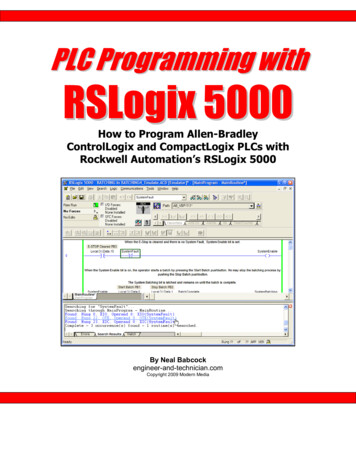
DirectSOFT5 IBox Instructions for DL06 PLCsAnalog Input/Output Combo Module Pointer Setup (ANLGCMB) (IB-462)1234S67891011121314ABCDDS5UsedHPPN/AThe Analog Input/Output Combo Module Pointer Setup instruction generates the logic toconfigure the pointer method for an analog input/output combination module on the firstPLC scan following a Program to Run transition.The ANLGCMB IBox instructiondetermines the data format and Pointeraddresses based on the CPU type, theBase# and the module Slot#.The Input Data Address is the startinglocation in user V-memory where theanalog input data values will be stored,one location for each input channelenabled.The Output Data Address is thestarting location in user V-memorywhere the analog output data valueswill be placed by ladder code orexternal device, one location for each output channel enabled.Since the IBox logic only executes on the first scan, the instruction cannot have any input logic.ANLGCMB Parameters Base # (K0-Local): must be 0 for DL06 PLC Slot #: specifies which PLC option slot is occupied by the analog module (1–4) Number of Input Channels: specifies the number of analog input channels to scan Input Data Format (0-BCD 1-BIN): specifies the analog input data format (BCD or Binary) - thebinary format may be used for displaying data on some OI panels Input Data Address: specifies the starting V-memory location that will be used to store the analoginput data Number of Output Channels: specifies the number of analog output channels that will be used Output Data Format (0-BCD 1-BIN): specifies the format of the analog output data (BCD orBinary) Output Data Address: specifies the starting V-memory location that will be used to source theanalog output dataParameterBase # (K0-Local) . . . . . . . . . . . . . . . . . . . . . . . KSlot # . . . . . . . . . . . . . . . . . . . . . . . . . . . . . . . . . KNumber of Input Channels . . . . . . . . . . . . . . . . KInput Data Format (0-BCD 1-BIN) . . . . . . . . . . . KInput Data Address . . . . . . . . . . . . . . . . . . . . . . VNumber of Output Channels . . . . . . . . . . . . . . . KOutput Data Format (0-BCD 1-BIN) . . . . . . . . . KOutput Data Address . . . . . . . . . . . . . . . . . . . . . V6DL06 RangeK0 (local base only)K1-4K1-8BCD: K0; Binary: K1See DL06 V-memory map - Data WordsK1-8BCD: K0; Binary: K1See DL06 V-memory map - Data WordsDL06 Micro PLC User Manual Supplement - IBox Instructions
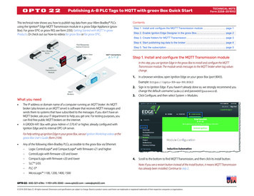
DirectSOFT5 IBox Instructions for DL06 PLCsANLGCMB ExampleIn the following example, the ANLGCMB instruction is used to setup the pointer methodfor an analog I/O combination module that is installed in option slot 2. Four input channelsare enabled and the analog data will be written to V2000 - V2003 in BCD format. Twooutput channels are enabled and the analog values will be read from V2100 - V2101 in BCDformat.No permissive contact or input logic isused with this instructionDL06 Micro PLC User Manual Supplement - IBox Instructions71234S67891011121314ABCD
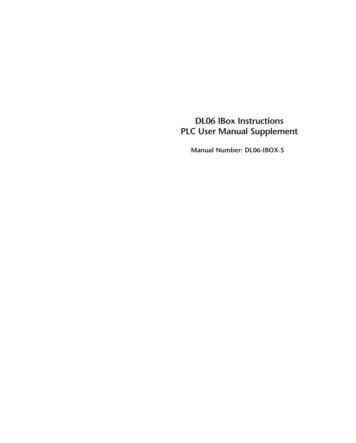
DirectSOFT5 IBox Instructions for DL06 PLCsAnalog Input Module Pointer Setup (ANLGIN) (IB-460)1234S67891011121314ABCDDS5UsedHPPN/AAnalog Input Module Pointer Setup generates the logic to configure the pointer method forone analog input module on the first PLC scan following a Program to Run transition.This IBox determines the data formatand Pointer addresses based on theCPU type, the Base#, and the Slot#.The Input Data Address is the startinglocation in user V-memory where theanalog input data values will be stored,one location for each input channelenabled.Since this logic only executes on thefirst scan, this IBox cannot have anyinput logic.ANLGIN Parameters Base # (K0-Local): must be 0 for DL06 PLC Slot #: specifies which PLC option slot is occupied by the analog module (1–4) Number of Input Channels: specifies the number of input channels to scan Input Data Format (0-BCD 1-BIN): specifies the analog input data format (BCD or Binary) - thebinary format may be used for displaying data on some OI panels Input Data Address: specifies the starting V-memory location that will be used to store the analoginput dataParameterBase # (K0-Local) . . . . . . . . . . . . . . . . . . . . . . . KSlot # . . . . . . . . . . . . . . . . . . . . . . . . . . . . . . . . . KNumber of Input Channels . . . . . . . . . . . . . . . . KInput Data Format (0-BCD 1-BIN) . . . . . . . . . . . KInput Data Address . . . . . . . . . . . . . . . . . . . . . . V8DL06 RangeK0 (local base only)K1-4K1-8BCD: K0; Binary: K1See DL06 V-memory map - Data WordsDL06 Micro PLC User Manual Supplement - IBox Instructions
DirectSOFT5 IBox Instructions for DL06 PLCsANLGIN ExampleIn the following example, the ANLGIN instruction is used to setup the pointer method foran analog input module that is installed in option slot 1. Eight input channels are enabledand the analog data will be written to V2000 - V2007 in BCD format.1234S67891011121314ABCDNo permissive contact or input logic isused with this instructionDL06 Micro PLC User Manual Supplement - IBox Instructions9
DirectSOFT5 IBox Instructions for DL06 PLCsAnalog Output Module Pointer Setup (ANLGOUT) (IB-461)1234S67891011121314ABCDDS5HPPAnalog Output Module Pointer Setup generates the logic to configure the pointer method forN/A one analog output module on the first PLC scan following a Program to Run transition.This IBox determines the data formatand Pointer addresses based on theCPU type, the Base#, and the Slot#.The Output Data Address is thestarting location in user V-memorywhere the analog output data valueswill be placed by ladder code orexternal device, one location for eachoutput channel enabled.Since this logic only executes on thefirst scan, this IBox cannot have anyinput logic.UsedANLGOUT Parameters Base # (K0-Local): must be 0 for DL06 PLC Slot #: specifies which PLC option slot is occupied by the analog module (1–4) Number of Output Channels: specifies the number of analog output channels that will be used Output Data Format (0-BCD 1-BIN): specifies the format of the analog output data (BCD orBinary) Output Data Address: specifies the starting V-memory location that will be used to source theanalog output dataParameterBase # (K0-Local) . . . . . . . . . . . . . . . . . . . . . . . KSlot # . . . . . . . . . . . . . . . . . . . . . . . . . . . . . . . . . KNumber of Output Channels . . . . . . . . . . . . . . . KOutput Data Format (0-BCD 1-BIN). . . . . . . . . . KOutput Data Address . . . . . . . . . . . . . . . . . . . . . V10DL06 RangeK0 (local base only)K1-4K1-8BCD: K0; Binary: K1See DL06 V-memory map - Data WordsDL06 Micro PLC User Manual Supplement - IBox Instructions
DirectSOFT5 IBox Instructions for DL06 PLCsANLGOUT ExampleIn the following example, the ANLGOUT instruction is used to setup the pointer methodfor an analog output module that is installed in option slot 3. Two output channels areenabled and the analog data will be read from V2100 - V2101 in BCD format.1234S67891011121314ABCDNo permissive contact or input logic isused with this instructionDL06 Micro PLC User Manual Supplement - IBox Instructions11
DirectSOFT5 IBox Instructions for DL06 PLCsAnalog Scale 12 Bit BCD to BCD (ANSCL) (IB-423)1234S67891011121314ABCDDS5HPPAnalog Scale 12 Bit BCD to BCD scales a 12 bit BCD analog value (0-4095 BCD) intoN/A BCD engineering units. You specify the engineering unit high value (when raw is 4095), andthe engineering low value (when raw is0), and the output V memory addressyou want the to place the scaledengineering unit value. The engineeringunits are generated as BCD and can bethe full range of 0 to 9999 (see ANSCLB- Analog Scale 12 Bit Binary to Binary ifyour raw units are in Binary format).Note that this IBox only works withunipolar unsigned raw values. It doesNOT work with bipolar or sign plusmagnitude raw values.UsedANSCL Parameters Raw (0-4095 BCD): specifies the V-memory location of the unipolar unsigned raw 0-4095unscaled value High Engineering: specifies the high engineering value when the raw input is 4095 Low Engineering: specifies the low engineering value when the raw input is 0 Engineering (BCD): specifies the V-memory location where the scaled engineering BCD value willbe placedParameterRaw (0-4095 BCD) . . . . . . . . . . . . . . . . . . . . . V,PHigh Engineering . . . . . . . . . . . . . . . . . . . . . . . . KLow Engineering . . . . . . . . . . . . . . . . . . . . . . . . KEngineering (BCD) . . . . . . . . . . . . . . . . . . . . . V,P12DL06 RangeSee DL06 V-memory map - Data WordsK0-9999K0-9999See DL06 V-memory map - Data WordsDL06 Micro PLC User Manual Supplement - IBox Instructions
DirectSOFT5 IBox Instructions for DL06 PLCsANSCL ExampleIn the following example, the ANSCL instruction is used to scale a raw value (0-4095 BCD)that is in V2000. The engineering scaling range is se
6 DL06 Micro PLC User Manual Supplement - IBox Instructions DirectSOFT5 IBox Instructions for DL06 PLCs 1 2 3 4