Transcription
s.,s'-'IUGCO ENGINEERING 4.0-71fCABLE TRAY HANGER AS-BUILT05-06-851BY., O. S. ,W" BOLT IOLE VERIFICATION"IPREPAREQ,/y&gUNIT NO. 2-,0/h 10011.0f/3/35{1APPEOVED BY1 of 21or'REFERDJCES1-A CP-EI-4.5-23 Cable Tray Hanger Engineering Walkdown1-B CP-CR4-6.3 " Preparation, Approval and Control of OperationTravelers1-C CP-EI-4.0-68 Cable Tray Hanger As-Designed and As-BuiltDrawing Development1-D CP-EP-16.3 Control of Reportable Deficiencies2.0GENERAL2.1PURPOSE-This instruction outlines basic responsibilities and tasks for thedevelopnent of " Bolt Hole Verification" for Cable Tray Hangers (CTH)for Unit #2, and provides the verification criteria that shall beused to document bolt holes in attachrmnt to' concrete, structuralsteel, tray supports and clamps (plate or angle).2.2SCOPEThe two hundred and thirty (230) cable tray hangers of Unit #2 willbe randomly selected from those whicil were installed beforeJanuary 1984 (the same time period for Unit #1 CTH installations).'Ihese randomly selected cable tray hangers of Unit #2 will also beusedfor the " Bolt Hole Verification" for the bolt hole sizes in Unit#1 CTH. %*]-.8605300251PDRFOIA-860523GARDE 86-A-55.PDR3.u
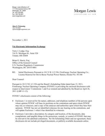
.-o.'. IUGCO ENGINEERING 0-71.2.3105-06-852 of 21GENERAL PROGRAM DESCRIPTION'Ihe " Bolt Hole Verification" drawing shall be prepared by theengineering walkdown team showing bolt size, bolt type, and telthole identification numbers for:.,(a) Attachment to cancrete (bolt holes in plate, angle or.channel for Hilti/ Richmond bolts) (b) Attachment to structural steel (bolt hole in channel,angle, or plate)(c) Attachment of Cable Tray Clamps to support (bolt holein channel, angle, or other structural member)(d) Splice plate, washer plates, and angles attached totray (tolt hole in plate or angle)2.4RESPONSIBILITY-'Ihe CPP Project Civil Engineer is responsible for providingtechnical direction and administrative guidance to the CPP CivilEngineering Organization of which the Unit 1 CTH Special AnalysisGroup is a part.'Ihe CTH Prcgram Manager is responsible for ensuring activitieswithin the purpose and scope of this instruction are completed inaccordance with the measures described herein.The Cnl Supervisor is responsible for implementing thisinstruction. 'Ihe CTH Supervisor shall coordinate the asseniolyand transmittal of " Bolt Hole Verification" packages, interfaceactivities, and establish and maintain adequate trackingmechanisms or logs to assure positive control of all activitiesi;described within this instruction.When specific individuals are designated by title in thisinstruction, it shall be assumed that a designee may act inthat capacity. Documentation of such designation shall beimaintained within the Cable Tray Hanger Group.Ms 1e
.'IUGCO ENGINEERING 0-71105-06-853 of 21 -3.0INSTRUCTION3.1INITIATION.,3.1.1General@e Cable Tray Hanger Engineering group shall prepare and transmitapproved " Bolt Hole Verification" drawings to DCC/ Paper Flow Group(PEG) for assembling specific " Bolt Hole Verification" drawingand operation traveler in a package for QC inspections. Wepackages shall be controlled by Unit #2 PEG.3.2CTH ' ':uT HOLE VERIFICATION" WANN3.2.1Ibcumentation of Verification Activitieshe CTH Supervisor shall maintain on a file, a list of individualsapproved to coordinate and document field verificationactivities.The QC shall document all inspection attributes per ConstructionOperation Traveler (Traveler) (Attachment 5) and shall be trained inuse of Traveler and related attachment. W e QA department willconduct the Traveler QC training.3.2.2Engineering WalkdownThe engineering walkdown team shall walkdown the CI'H and preparea drawing identifying ead bolt hole with a unique number foreach joint having bolted connections. 'Ihe complete drawing willcontain as a minimum information shown on Attachment 1 for eachunique bolt hole. To faciliate QC documentation the boltinformation will be sumarized as shown on Attachment 2. We " BoltHole Verification" drawing for each specific support shall bereviewed by the " Bolt Hole Verification" Supervisor and approved.Upon approval, the drawing shall be transmitted to DCC fordistribution.3.2.3.},,Operat nal TravelerThe craft (construction) will remove the bolts and nuts in sud asequence that the hanger may remain in a safe condition includingtie-offs to adjacent structures or prop up as necessary anddocument on the Traveler (Attachment 5).'." gru
.11XXD EIGINEERING 71105-06-854 of 211The CC Inspector shall perform inspections listed on theTraveler and complete documentation on Table A and Table D(Attachment 5). These tables will be used for coapleteverification and documentation of tolt holes of individual randomlyselected Cable Tray Hangers and identified with suffix BH at theend of the drawing number (Attachment 1).3.3,REMOVAL OF BOLTS AND NUTS.-.The field engineering or construction craft shall renove allbolts and nuts as specified on " Bolt Hole Verification" drawingfor the specific cable tray hanger. Loose parts resulting fromrenoval of the bolts shall be secured to the hanger.3.4THE AS-BUILT " BOLT IDLE VERIFICATION"The.QC inspector will document on Tables A & D (Attachment 5) all;'-inspection attributes. Tables B & C (Attachment 5 are used for thisinspection and are referenced in the Traveler. After completion ofall QC documentation on the Traveler (Attachment 5) the package willthen be returned to the Cable Tray Hanger Group.3.5EtGINEERING EVAUJATICN:The Cable Tray Hanger Group shall evaluate each CrH package aftercompletion of CC inspection on the basis of the followingacceptance requirements.3.5.1Bolt Holes3.5.1.1Attachment to Concrete(a)Bolt hole sizes for anchors (Hilti Super Kwik Bolts,HiltiKwik Bolts and (Richmond) Screw Anchors shall be asfollows:1) 3/16" larger than nominal bolt diameter (max) forbolts up to and including 1 1/4" diameter.*3.5.1.22)1/4" larger than nominal bolt diameter (max) for1 1/2" diameter bolts.Attachment to Structural Steel - (bolt holes on hanger andsupporting structural steel).Bolt hole sizes for bolts shall be 1/16" larger than the nominalbolt diameter.-'',.-.
-----.-.'IUXD DGINEERING 713.5.1.305-06-8515 of 21Attachment of Cable Tray Clamp (Angle) to support structure(a)iBolt hole size for 5/8" diameter H.S. bolt shall notexceed 3/4" diameter.(b) Bolt hole size for 5/8" diameter A307 bolt shall notexceed 11/16" diameter.;3.5.1.4Attachment of Cable Tray clamp (Plate or Angle) to Tray (bolt holein plate or angle)(a) Bolt hole size for 1/2" diameter round head bolt shallnot be larger than 9/16" diameter.(b) Bolt nole size for 3/8" diameter round head bolt shallnot ce larger than 7/16" diameter.3.5.22Washer and Washer Plate-43.5.2.1Washers arrl washer plates shall be verified for proper selectionand for tolerances per Attachment 3.3.5.3Edce Distance3.5.3.1For Engineering acceptance requirements of edge distance seeAttachment 4.3.6.DISCREPANCIES,!All discrepancies resulting from QC inspection and documentationshall be transmitted to EBASG) Special Analysis Group (SAG) - NewYork - for engineering resolution.3.6.1Dimensions not in conformance with Engineering AcceptancefRequirements:The engneer-(SAG) shall perform necessary calculation to determinethe acceptance of dimension not conforming to minimumrequirements: ,A.,'.'B.If after calculation it is acceptable to "Use As Is" SAG willconfirm that in writing to site C m Group., If after calculation it is not acceptable SAG will revise thedrawing to rework the affected unsatisfactory conditions.i-i,.-.-.--.-. - . ---.- - . . . - - , . . - . ,.---2*
. - . . . . . . -. . . . .*. .a.*,.'IUGCO ENGINEERIN3 1 105-06-85 6 of 213.7REINSTALLATION3.7.1'Ihe craf t shall reinstall tne nuts and bolts removed during QCinspection per the Traveler (Attachment 5).81'.' .;3.7.2'Ibe QC Inspector will perform installation inspection of boltsand nuts and sign off the Traveler (Attachment 5). Anyunsatisfactory condition during reinstallation shall be recorded-)'on Inspection Reports (Attachment 6).3.8IDCUMDTIATIONThe QC Inspector will document the inspection of bolt holes onthe Traveler (Attachment 5). Inspection Reports (Attachment 6) shall be used to docunent allunsatisfactory condition and a copy will be sent to CIH Group.3.8.1REPORTS AND SUMMARY'Final reports and sumnary shall be prepared by SM to analyze theresults and recommndation to site engineering. 'Ihis report willbe sent to Site Civil Engineering to transfer to the vault.i !i !:1ifMi15'spsIi*o4!- .- . . . . ,. . . - ,. - - . . - . , , - . . - - . . . .- -. ,. ,. .-. - ,--. - -, .i'.') .
.'.IUGCO ENGINEERING -7105-06-8517 of 21ATTACliMENT 1tNOTES 4**- 2 li'# Hti.Tl Kwit. tbOLTSLG,.,.-@-,,N'r. SWO iwo.c4Te.s c - o i- ex.-r r'tNem6&A.&g &. .,]"'./ MC c,s t.'s 4.,-(ky,gax,,.LG.G.4wwww wa sywgxi/ " L. A-7SEC.T b-bSECT A-ALY2a2't.5,,g.4Lc,,2 't*@ abo] BOLTS--2. 62 o Atai tWLibL S't albI.-. . .-s\.-., '5. . . g r. - .--. ' \MCGMCGaS'd{s'e2'TQ3'2aftal.&c. t g2 ; s"4 ,/.-!.!:cL cco.n'cccT D-Dc,,:.'. ,j.-i*''TEXAS UTILITIES -htco ico.3''"-GENERATING C0.,:1 w.c,.is.3 (, . EBASCO SERYICES INCORPORATEDSECT F FCABLE TRAY HANGERBOLT HOLE VEFJFICATioNCLASS 1,( NUCLEAR SAFETY-REL ATED),C. P. E E. L DW MO.SAFETY CLASS 1 SEISMIC CATECCRT 1SAFErv class 2 class IE.ctra mostSAFETY CtASS 3 ASSOCIATED CIRClif fS. .W.e - -'7" "*' 8m.: % , . . ,.:. .:.,!:,t,Y.-M*:"'L%'[L5't 2'zi,9ty2-'""ma rs 3 3.ySECT E-E.;"' --.-\- \,SECT C-C, .l*g 7. , LTIEASM T.CTH-2 'Dx/x-OH01f- - - - . - - - -a . . . ., . -.--- - - . - ---- - - -.M---. ,
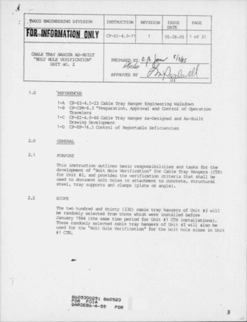
. .*.WINEERING 0-7105-06-851. 8 of 21ATTACINENT 24.I',3--.*t'i.I3OLT HOLE TABLEBOLT IOLEUNICUE NUMBER,BOLT EOLTDIATYPECONNECTION@ CONCREIE@ STRUCTURAL STEELTRAY CIAMPS@ SUP STR@ TRAYREMARKS,.i*.-iMvI,tg' - - - . - - . ---. . .,
.TUGCD ENGINEERING DIVISION.INSTRUCTIONREVISIONISSUEPAGEDATEC P-EI-4. 0-7105-06-8519 of 21ATTACHMENT 3HOLE VERIFICATIONBOLT. WASHERS AND WA5HER PLATESMCLIPW"ER\h].('jeswe isciRcutuz m saERw'%FOR l BOLT58FOR 34 BOLTFOR 88 BOLTkFORbFOR.'t5BEVELED WASHEPs'zFOR l'2 BOLTFOR l' ECLT'4ScLT8 EOLT , 'aMNCIRCULARWA5HER.'D 68FOR '1' 4'2'4MAY BE 'A MIM. *FOR %" / 59;s iMAY BE5i6 MIN.:%' :m eoet MAY nTRIMMED IF REQUIREDTo CLEAR AN INTERFE.RENCE.':. . . . .O'O' 38MAY BE '4 MIN. *(TTR)WASHER' PLATESREQUIREO INSIDE TRAYS E4' AND OVER AT HEAVY OUTY CLAMPS. , . . .-.x.;. :e
*,.1'IUGCO ENGINEERING 0-7105-06-851ATTACHMENI' 410 of 21Sheet 1 of 4'. !!-.--BOLT H0LE VERIFICATIONBOLT H0LE GAGE AND EDGE DISTANCE FOR ANGLES'L8 S4MMMUMDMe rsee tun)%,-sD734*AL C, S4LS 46AA6l'1*# RICHkCNOl's*/sl'sl'al'90CHMONOl(Syg[(l'4'# HiLTl1,5,,c5%l' * HILTIl'.S.1%1%lb5% (l ','68A6XX[7gXX'BOM EA6A6lkIy.[kMm uAsy3bSh 5Sfgy, 3(CNE ROWl!MWJMn34''TWO ROMjL5 SsOWD)510M38 '#,1A 8 lbL abAlbY"4L% 4ABA%Blb%lb%(G"TRAW4*lCITRAT5) (4' TRAY)gajawo gow3y p, ; 3,c, 7 gg 4,53*# AT TSl','c,IClhe ' gyy %.(TYO.i.QlfAAX) 'Az LENGTH Cf: ANCLEy,! [ n.'sAD%X XXXy y y g,L5 kMimMumI'L 3.%DOMENSIONA6L 4 s,c, t3 g.(A6 A 6ik 1% lb % lb %Ss "*'t* *W TRX (4*ar s L3'2 CNLY sG%FoR't L afetiv.0 Rav5) .l'r.: s, gp Le cNLY 4'% Fea's LsATrsl,1 c. it5% FcRSr.L"T5,,,igg,g gge( g,g{9 alptr Td%yA&A6lb%58%XXX X X K y Xil, ,it!(4" TRAY)VJ 'NADALL L DtM CA D 'EI: MIN MAXl'd 2'.@ l'vf2 'it'{ r,'j14341 **l' a5) l'es,ir4sIb lbX%--{. g,.;an' ,d.s,. .,!*'-,-.Il-. -
. .'IU;CO ENGINEERING DIVISIONINSTPUCPICNREVISIONISSUEtPICEDATEC P-EI-4. 0-7105-06-851ATI'ACNENT 4.30JHS11 of 21Sheet 2 of 4VER:CE ONMOLE.A'jo7 30LT, SOLTlbI l's.vAy3MIM i v.s.W G lGWG 'iGi% I 2 luAx Mig Ibiws is.9'l'2-W5''asL2ik 1 l'2 lvAs wu IMw419i11-1ca jugW4 0 ]ff"M'" b"'' 'lu n MIN lb]'2IMu uiu bjlit x-I :,,a 1L,gpb*Se "d BOLT IN T.EANSVERSE SUPT.Mn. l'4 ,W6N*FLC4,'s . MIN2'4 WG(G"FLG11 2.MAX ' d -2'A l. WGOE 5::c.43gbl'4 iW8(5'#LGkS8,MN1's W WG'2FLG) iC4ymax[* 2ekb-s,,.,'!da-tw4ogwGOg.9# xTogo,, SUIT,j' .o3C326oCr6o 5MINW8 lh,*g4P-jC;fCONN. TO MEMBER WEB* R W6 E*W W8"O' W8'IO A W8''9u ewt.y w a io,wa rs,4 ws m sCONM. TO MEMSE8 FLANGEz(ALL)ll'8, min2 8 j WS* jfeii3-TRAY Cl. AMP 5 N WlDE FLANGE BEAMSppCmax5s"o BOLT IM LOMGITUDINAL SUPT.eg.e5" "'rjrW3-aLO,--MEMBER END CONN. PLATE'FRAMING MEMBER CONNECTIONS-m.
,. .1s---;.,.,.,-CUX'O EN3INEERING .0-71'05-06-851ATTACa4ENr 412 of 21Sheet 3 of 4#:.,iBOLT HOLE VERIFICATION-BOLT EDGE DISTANCE AND SPACING FOR PLATESEDGE DiSTFOR ANY SOLT*A!BMIN k4'Gfa6'4#l**FJCHMcMO'46'2 *l'4'# H!LTl 6Yl'# HtLTI''4G'i #St# HILTI8sGYSa 'd HILil5h G,{'t'd HtLTI't#G'45/dH.S.80LTI6'[l 'ic,,k[yN'nl'4524lh4? ,ssN[yN7YgI'43'4lb4'15sSGY'is",CFadim Cft#RCHMCND"iDMhM G!D3E 015T!- !ega5Pg,[3s-%** H.5. E,0LT0 ', c[un'OPLATE 1ovn mc8 M LTie,wx,'],'' jgd-Ail'tLESS FORMit.2'a LESSPLATE II,-FOR %FE.3"Less rone.- ./.g. - . - .e. .- . .*e mO,.3-,-,,,. . - -
.*. .,.'IUGCO EtGINEERING 7105-06-851ATTACliME57f 413 of 21Sheet 4 of 4.BOLT HOLE VERtRCATIONBOLT HOLE GAGE AND EOGE DISTANCE FOR CHANRL5ILONGtTUO1 MALTRAN5 VERSEF-- SUPPORT 85"4 UPPORTS'sa'Di A A DIM 6DIM A CtM 6I"'o-.ime ea-7S"We gs'XC%,/ron c3 4 c4C44.4'tC4 7.29%%%4'tCG SZNCG*lO.9f'C(o a l* C8 ll.9c6 3,75' um pod'A ears kiun rce h*4ea.rs 'C8 ta79Cloil9.3c,h 2 M 0I '4L's53L53%g,(t *3'l%'t -LILl's'bbl's11 LMC3 7.1bkLbMC34'4MCG121MCG 15.15MCGile5MC G 6.35MC(oa l85a6eIl's'4%i'sIb53gTe',1'4'l'e'sit' 53'sla'4',L.tiLl'4'4',6,LI,5 .I'4'41,'sl'slic,'4!L'a)Ll'4'j'ga ss7C10 20'01M. C5'3liiILE.''XALL SufToR.15. .#486.-.mege.mggqgg,g,m, .?t. .s--,.4.*R. . . ;,,6m. . .- - - - - - - . - - . . - - - - - - - - - -- - -- - - - - - - - - - - . - - - - - . - - . - . - . - . - - - - - . . - . - -
., ,-.-,/[ # 7'w j;.t.'IUGCO DGINEERING DIVISIONINSTRUCTION.REVISION' ISSUE PAGEDATE-CP-EI-4.0-71'05-06-85114 of 21-1t',,sSheet'1 of 7[ ATTACHMENT 5, .,,L.t0ametaxvIm ceE:sATIoN wAvEt.ER ' 35-1195.11.19AVEL.ER to.3. UNIT to.2. EQUIRtENT NC.t ."CIlf-,6.14TIVITIY DESCRIPTION25. PAGE I of I4. QUANTITY7. REFEPOG D6AMINGS 9. LOCATI ei8. 5 PEE /P!OC/EcGR INST.10. SYSTEMQ'PRIPARED BYDATEilEVIEhED BYCATEN/AANI .% VIEWJOP.NO DEFFCEF"N/ADATE QA/QCCCNSTI DC.OPEM TIONSCOPE: Els traveler is teing used to remove and reinsr.all the bolts and nuts as required for allverification of tne bolt holes, edge distance and washe.c,(plates. 21s traveler will also document hole sizes., annoval of Ebits ard tuts:1.""'-"".foreInaccessible bolt holes need not be inspected'.2e bolt ntsnber, size and type colt:ms in Table A shallbe conpleted. Se other coltzarr, snall be lired throughand labelled " inaccessible".,ANI-"#11Craft Aemove toits and nuts snown on tne referenced " Bolt IbleVerification" drawirug. Bolts and nuts snould be renovedin sudt a sepence that the hanger may remain in a safe'"condition, tneluding tie-off to adjacent structures asnecessary. 1',"(V)2e QC Inspector shall sign off irditridual bolt renovalon Table A (page 4). Operation 1 to te signed off by Inspector verifying last tult/ nut reeval.QC(V)De CC Inspector shall docu: rent and sign off tndivf4ualbolt hole etqe distance on Taole A (page 4).QC-2,.,.,Bolt types shall be identified per Table B (page 5).i-Edge distances "A"& "B" to be oriented as shown us t:te"Ebit Hole Verification" drawing. Washer and wasnerPlate edge distance shall be cbcumented arte Table C,'p -(page 6).1'w-j,p,*.'1sxNsL. 9,f-'?.p,-,3 ' 'd".'%.'%n, ' . - - . , , , , . , , . .,m, - , -,--vv i,-,,-,-- -ever -- - - -* -N' ' A-" ' ' * *-
.'IUGQ ENGINEERIN3 7105-06-851ATTACfEENT 515 of 21Sheet 2 of 7''CCNSTPUCTION OPEPATION TRAVEIIR 35-1195.l.2. EQJIP!Ctr 20,TBAM 20.3. UNIT to.4. QUrWIITY5. PM E 2 ot -C121-7. REFERENCE DRAWINGS6. ACTIVITIY DESCRIFFIONPREPARED BYCATEREVIDED BYDATEDEPTN/ADMSN/AANI REVIEW10. SYSrm9. LOCATIud8. SPEr./PIOC/ ENGR INST.CA/QCOP.tr DEPP3QC(v)CCNSTOPERATIONE.MReinstallation of Bolts and Nuts:'Ihe QC to sign off installation of irdividual bolts andnuts en Table D (page 7).Docunent unsat conditions onthe attacned IR, and list the IR ntancers in theapplicable section below. Tensioning criteria is givenbelow for eacn type of attachment. Operation 3 to besigned off by QC inspector verifying last bolt / nutreinstallation.A.Attacc.ent to ConcreteScrew AnchorI.Install to a " Snug-Tight" conditionunsatisfactor/ cordittens listedon IR:II. Hilti Bolt NutsInstall to a "Ibrque" corditionUnsatisfactory conditions listedcn IR:tbeque Pequirements:Bolt Diameter(Inches)Ibrque(Ft-Lbs)1/48173/81/2,; 'dP/83/4170120150'DO1 1/4400.g .b.-- wy,w-,r*r -.-.
---.'IUGCO ENGINEERItG DIVISIONINSTRUCTIONREVISICNPME, ISSUEDATECP-EI-4.0-7105-06-85116 of 21i.- Sheet 3 of 7ATTACIEENT 5.''CONSTIUCTION OPERATION TRAVELER 35-11953. TPAprn NO.2. EQUIPMDrr !O.Cni-6. MTIVITIY weenlPr!ONJ. UNITto.4. QUANTITY5. PME 3 & 77. EtEFERENCE DhWIMMi8. SPT/PIOC/CGR IdST.9. IDCATICN10. SYSTDt4'PREPARED BYDATEItEVIDiED BYCATEANI 34EVIEWN/ACATEDEPTN/A CA/QCOP.W DEPP OPERATION3GCcent. (V)(I)M;TANIENG.B. Attadment to Structural SteelInstall to a " Torque" conditionUnsatisfactory Conditions Listed on IR(2beque Value itequirements)5/8"A H.S. Bolt - Torque Value 228 Ft-43/4"# H.S. Bolt - Tbeque Value 387 Ft-67/8"# H.S. Bolt - Ibeque value 518 Ft-t1"A H.S. Ebit - tbcque value 725 Ft-4),C. Attadment (Clanps) to TrayI)-*Attact1 ment to StructureInstall to " Snug-Tight" condition for A307 boltsInstall to "ibrque" condition for H.S. boltsUnsatisfactory condition listedon IR:tbrque requirements for H.S. bolts(!be 5/8"# H.S. Bolt Torque 228 Ft-Ibs)Attactment to TrayII)Install to a " Snug-Tight" corditicoUnsatisfactory condition listedm IR:4CECC(V);Verify expletion of all operations, and review travelerand attac:nents.'is&.4*{.4fj. , . -. . , --- --- '"*' ' ' * ' - '' " ' J '
,. .'ItXiCO ENGINEERING 7105-06-85117 of 21Sheet 4 of 7ATTACHMENT 5-. .*.TABIE A1. TRAVELER to.BOLT MO 14ff REMOVAC. INSPfCTION 00CIND(RATIONBOLT IOLE/ EDGE DISTA!CE/WASHER PEATECOCUMt2(TAf!ON2. tDJIPMC(T 20,C1H -5.Page 4 of 7'3. (NIT70.tRET(Per Het ilsg)TW4DOLT & MJIlOLtto.BOLT 10LEplNOVEDifilti/Screw toch cH.S.DIA.(Inch) A307EDGEDISTANCEDOCLMD(RATIONA.E!LEDIST.BDIA.OA/0C DATE(Inch) W QC[ WIT !!O!WSHER ftATEEDX EDIEWAS!!ERaCIS'I DISTItci CA/QC CATE TYPE ( Inch )' CA/CC DATECDQA/CDATE.6aBI.--, .,. w p , . . . .,. , .as. , , , , , ,--, , , , ,, , ,.-.c,. o.1,I":*.-)%.--1Ii11I*I1,- . . . .-- - - . . -. . --. - - . . - - ,, - - .-. e., .--,- - - . - --.J-
.,.- . . . .-.i-. .,'I--- -.TJGCO DEREERItC DJ. VISION.- - - -,INSTRUCTIGttREVISICNI-ISSUEDATEm:CP-E::-4 40 ' 5--PAGE0 -06-85 : 16 of 2111m, ,ATIF.lih NI' 5,.Sbeet 5 of 7.-*'q%ts a, X,T IDENTWICf.TICN MRKIICOaMT.:.,"*5.--' -Steet 5 of 7WIY 2. tT)J iME *3.--1.Ccm -m.--',f15 7M QAl,t).;*CS' CGJJM MAft"(JC CCA'37EEL- ---gkD. E 0 ** (k -:,;:;aNf :29fC/f/CEI/6LO;.C.2RCE MG ?flAM:,.4At\:SACI[ ilAL----.-.*-.GhanE ylow t't kidDat/M,G140ca/ 3YEZL-A m-.,UWCANOCY Z?d5L, ASTM * A Aq31*ouewuca wa notrec, , , , , , , , ,w ---ggg ,-,\ACTM - R,9fg,avenaaorwu m-uwm - uawo**n-SoftylltW (*QRg0f./ STC(Qva J 'M3.?4tM - 9 225 ?,LOW CASW W i?{USEN Nejgy ,.;0menvM tooseu.:na,:%1uwer unas::a carrou gras d''''''#'''b-g,.wr o nce eaio aux,.,LCat CARA.34 M29 TEA 2riA:6" EELTvat a.- 104' Tv
2.3 GENERAL PROGRAM DESCRIPTION 'Ihe " Bolt Hole Verification" drawing shall be prepared by the engineering walkdown team showing bolt size, bolt type, and telt hole identification numbers for:. (a) Attachment to cancrete (bolt holes in plate, angle or, . channel for Hilti/ Richmond bolts)