Transcription
NRC CraneInspectionsTaiwan ISFSI WorkshopDecember 9, 2008Ray Kellar, P. E., RIV Inspector817-860-8164Ray.Kellar@nrc.gov1
Outline ISFSI Crane InspectionsCrane & Heavy Load BackgroundUtility Crane UpgradesRecent Crane Inspections & FindingsSummary2
ISFSI Crane InspectionProcess Fuel handling crane inspected as part of ISFSI preoperational inspections– Includes site specific requirements– Site performs demonstration using weighted load to simulatecask load Heavy Load Database developed which includesrequirements from:–––––NUREG 0612 – Control of Heavy LoadsNUREG 0554 – Single-Failure-Proof CranesANSI N14.6 – Special Lifting DevicesASME B30.2 – Overhead CranesASME B30.9 – Slings3
Crane & Heavy LoadBackground Crane requirements at nuclear facilities inUS have evolved over the past 40 yearsbased on industry experience:– Branch Technical Position APCSB 9-1 reviewedutility cranes for meeting single failure proofcriteria used in mid-1970’s (precursor of NUREG0554)– NUREG 0554 “Single Failure Proof Cranes forNuclear Power Plants” issued in May 1979– NUREG 0612 “Control of Heavy Loads atNuclear Power Plants” issued January 19804
Crane & Heavy LoadBackground Crane requirements (continued)– ANSI / ASME B30.2 “Overhead and GantryCranes” originally issued in 1967– ASME NOG-1 “Construction of Overhead andGantry Cranes” issued in 1983 Supplemental requirements are derivedfrom:– ANSI N14.6 – Special Lifting Devices– ASME B30.9 – Slings5
Branch Technical PositionAPCSB 9-1 Position developed to control design,operation and testing of single-failureproof cranes since no industry codesexisted at the time Provided consistent basis for review ofequipment and components for cranesystems Required dual components, auxiliarysystems or ancillary systems to retainand hold the load in a safe position Evolved into NUREG 05546
NUREG 0554Single-Failure-Proof Crane NUREG 0554 issued in 1979 Provided specific criteria for single-failureproof cranes that is still in use today Included criteria for:–––––––Material propertiesSeismic designWelding requirementsHoisting machineryBridge and trolleyWire ropeTesting and preventative maintenance7
NUREG 0612Control of Heavy Loads Integrated approach to dealing with cranerequirements and heavy loads Included requirements from other industry codesoverhead cranes (ANSI/ASME B30.2); SpecialLifting Devices (ANSI N14.6); Slings(ANSI/ASME B30.9); Single-failure-proof cranes(NUREG 0554) Allowed use of non-single-failure-proof cranes forhandling loads as long as:– Radiological dose to public below Part 100 limits andexpectation that dose should be less than 25 % of Part100 limits(25 Rem whole body / 300 Rem thyroid)– Reactivity of fuel remained below 95% (Keff) duringaccidental drop.– No damage to equipment in dual safe shutdown paths.8
NUREG 0612Control of Heavy Loads Stipulated use of Safe Load Paths tolimit damage to plant Provided allowances for operatingnuclear plant upgrades to existingcranes to meet the requirements ofNUREG 05549
ANSI / ASME B30.2Overhead Cranes Utilized at all nuclear plants Provides requirements for overheadcranes:– Construction– Installation– Inspection– Testing– Maintenance– Operator qualifications & training10
ASME NOG-1Nuclear Facility Cranes Provides requirements for overheadcranes at Nuclear facilities Code will be used for constructionand installation of new cranes– Structural components– Mechanical components– Electrical components– Inspection and testing– Packaging, shipping, receiving, storageand handling11
Crane SupplementalRequirements ANSI N14.6 – Provides requirements for speciallifting devices:– Defines critical load that could affect safety relatedsystem or result in offsite radiological releases– Requires design stress factors of 3 for yield stress and5 for ultimate stress– Requires dual load paths or increased stress factors of6/10 for lifts of critical loads– Load test conducted for 150% of rated load or 300% forcritical loads ANSI / ASME B30.9 – Provides requirements forslings:– Wire rope and synthetic material– Inspection and testing requirements12
Utility Crane Upgrade Many plants elect upgrade to non-singlefailure-proof crane Upgrades consist of:– Trolley and hoist replacement– Seismic analysis of crane (trolley, bridge, endtrucks) down to crane rail– Seismic analysis of building structure(foundation to crane rail)– Typically involve modifications to buildingconnections and support structure13
Utility Crane UpgradeTrolley The existing trolley is replaced with anew trolley complete with singlefailure-proof main hoist New trolley weight must beconsidered in seismic analysis Perform 125% load test of new mainhoist and auxiliary hoist14
Utility Crane UpgradeBuilding Capacity Many of the original building seismiccalculations were performed by hand New computer analysis may indicateoverstressed joints and membersrequiring modifications Must include weight of new trolley incalculations Errors discovered in old calculationsdealing with assumed buildingconditions (degrees of freedom)15
Utility Crane UpgradesLicensing Requirements Decision to use 10 CFR 50.59 processor use License Amendment:– What is original license basis?– Changes needed to Plant License orTechnical Specifications?– Specific conditions embedded in FSAR?– Increase in maximum crane capacity canbe made using 50.59 process– Most crane upgrades use 50.59 process16
Utility Crane UpgradesInspection Requirements Regulatory inspection of craneupgrades:– What is the licensing basis?– Has the single-failure-proof crane beenreviewed by the NRC before in a TopicalReport?– Matrix of how the crane meets the licensingrequirements– Review records of the crane design,installation and testing17
Recent Crane Inspections &Issues Region II Plant (2004)– Crane was single-failure-proof with 125 ton capacity– The NRC demonstration occurred with no problems– During the initial cask loading the crane experienced 2 trips whencarrying the fully loaded canister– Crane inspected after trips with broken rail bolts identified– During the repair of the broken rail bolts, weld cracks were foundon all 4 bridge trucks located near the concrete walls– Over 20 weld and base metal cracks were repaired– Licensee had not inspected bridge truck welds because they werenot considered to be critical welds by the crane vendor18
Recent Crane Inspections &Issues Region IV Plant (March – May 2006)– Crane capacity limited to 75 tons– First use of TN light weight transfer cask (OS197L)– Crane operational considerations were high priority due topotential dose rates– Licensee unable to find documented inspection of cranebridge structural welds after initial load test– Engineering firm performed seismic analysis for the AuxiliaryBuilding which indicated overstress conditions existed inbuilding columns during seismic event. NRR staff enlisted toreview licensee calculations.– No analysis had been performed for the supporting cranerails and girders during seismic event19
Recent Crane Inspections &Issues Region IV Plant (October – November 2006)– Initial 125% load test preformed in 1980, withoutrecording ambient temperature. Cold-proof testingrepeated prior to cask loading.– Inoperable bridge & trolley travel limit switches (onlythe hard stops existed)– Incorrect viscosity lubricating oil found in bridge driveunit and hoist motor gearbox showing high levels ofparticulate, materials and moisture– Hoist primary bull gear & pinion found dry and galled.– Licensee could not confirm operability of load dropprotection20
Recent Crane Inspections &Issues Region IV Plant (October – November 2006)Licensee initiated a testing program resulting in thefollowing additional findings:– Inoperable wire rope equalization system– Load cell was found disabled– Hoist motor over current relay found off-scale high.Relay would not have engaged until the hoist motorwas loaded with 250-tons– One of the two sets of mechanical load brakes wasfound inoperable– Crane had never been turned over for operational use21
Recent Crane Inspections &Issues Region II Plant (February – March 2007)– Non-Single-Failure proof 125-ton Whiting Crane– Part 21 issue identified in 2006– No safety related systems near or under the floor of thetransport path– Licensee hired the dry cask vendor to perform caskdrop analysis for canister. Analysis indicated thatcanister would not breach and therefore the Part 21dose limits would not be exceeded.– Licensee had not addressed that the fuel would remainsubcritical (NUREG 0612 , Section 5.1.II – Keff .95)22
Recent Crane Inspections &Issues Region I Plant (July - August 2007)– Licensee performed major modification to building fornew expandable gantry crane– Expandable gantry crane fabricated and fully load testedat fabricator due to extension over spent fuel– Agency initially believed licensee had to perform 125%load test after crane had been erected at licensee facility– Licensee had committed to older version of ASME B30.2, which did not require 125% load test after erection– Licensee will be permitted to use crane taking credit forload test performed at fabricator23
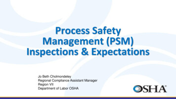
Recent Crane Inspections &Issues Region I Plant (July - August 2007) Slides24
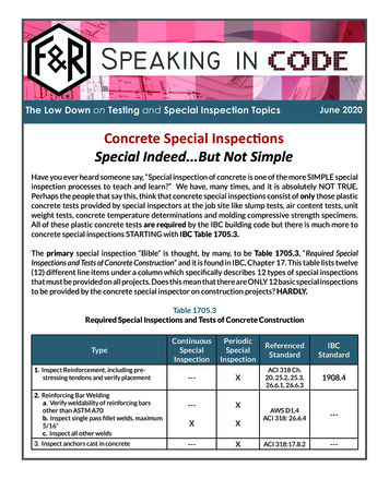
Recent Crane Inspections &Issues Region I Plant (July - August 2007) Slides25
Summary Heavy loads are the highest risk activity associatedwith dry fuel storage The crane issues have been different at each site. All of the issues could have been avoided by thelicensee by performing a thorough inspection of thecrane and the associated documentation prior to theinspection Many of the new licensees are replacing or upgradingtheir cranes to single-failure-proof instead of using theexisting equipment26
27
– ASME B30.2 – Overhead Cranes – ASME B30.9 – Slings. 4 Crane & Heavy Load Background Crane requirements at nuclear facilities in US have evolved over the past 40 years based on industry experience: – Branch Technical Position APCSB 9-1 reviewed utility cranes for meeting single failure proof criteria used in mid-1970’s (precursor of NUREG 0554) – NUREG 0554 “Single Failure .