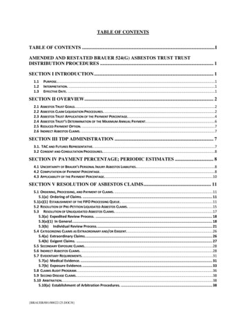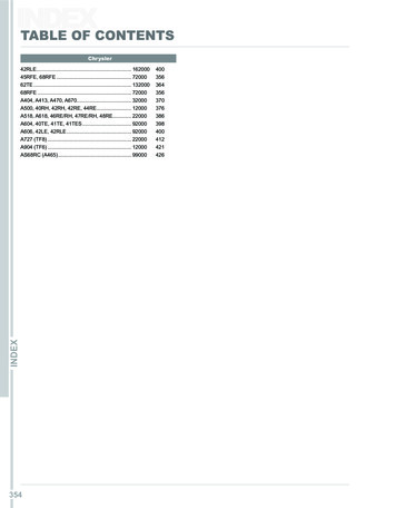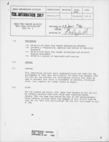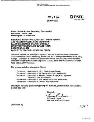
Transcription
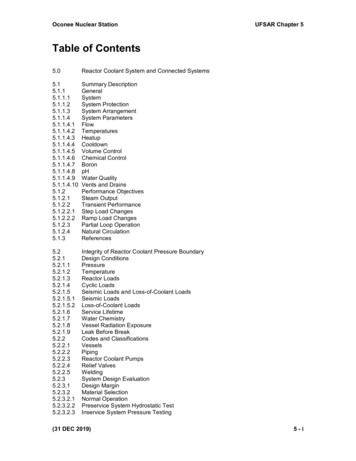
Oconee Nuclear StationUFSAR Chapter 5Table of Contents5.0Reactor Coolant System and Connected 2.25.1.2.2.15.1.2.2.25.1.2.35.1.2.45.1.3Summary DescriptionGeneralSystemSystem ProtectionSystem ArrangementSystem ParametersFlowTemperaturesHeatupCooldownVolume ControlChemical ControlBoronpHWater QualityVents and DrainsPerformance ObjectivesSteam OutputTransient PerformanceStep Load ChangesRamp Load ChangesPartial Loop OperationNatural grity of Reactor Coolant Pressure BoundaryDesign ConditionsPressureTemperatureReactor LoadsCyclic LoadsSeismic Loads and Loss-of-Coolant LoadsSeismic LoadsLoss-of-Coolant LoadsService LifetimeWater ChemistryVessel Radiation ExposureLeak Before BreakCodes and ClassificationsVesselsPipingReactor Coolant PumpsRelief ValvesWeldingSystem Design EvaluationDesign MarginMaterial SelectionNormal OperationPreservice System Hydrostatic TestInservice System Pressure Testing(31 DEC 2019)5-i
Oconee Nuclear StationUFSAR Chapter 5.2.3.13.35.2.3.13.45.2.4Reactor Core OperationReactor VesselStress AnalysisReference Nil-Ductility Temperature (RTNDT)Neutron Flux at Reactor Vessel WallRadiation EffectsFracture Mode EvaluationPressurized Thermal ShockClosure (Reactor Vessel)Control Rod Drive Service StructureControl Rod Drive MechanismCharpy Upper-Shelf EnergyIntergranular Separation in HAZ of Low Alloy Steel under Austenitic SS 5.3.3.25.3.3.35.3.3.45.3.3.55.3.3.6Reactor VesselDescriptionVessel MaterialsMaterials SpecificationsSpecial Processes for Manufacturing and FabricationSpecial Methods for Nondestructive ExaminationDesign EvaluationDesignMaterials of ConstructionFabrication MethodsInspection RequirementsShipment and InstallationOperating ConditionsSteam GeneratorsReliance on Interconnected SystemsSystem IntegrityOverpressure ProtectionSystem Incident PotentialRedundancySafety Limits and ConditionsMaximum PressureMaximum Reactor Coolant ActivityLeakageSystem Minimum Operational ComponentsLeak DetectionQuality AssuranceStress AnalysesShop InspectionField InspectionTestingTests and InspectionsConstruction InspectionInstallation TestingFunctional TestingInservice InspectionReactor Vessel Material Surveillance ProgramOconee 1Oconee 2Oconee 3Integrated Surveillance ProgramReferences(31 DEC 2019)5 - ii
Oconee Nuclear .4.8.35.4.8.45.4.8.55.4.8.65.4.8.6.15.4.9UFSAR Chapter 5Inservice SurveillancePressure - Temperature LimitsDesign BasesLimit CurvesReferencesComponent and Subsystem DesignReactor Coolant PumpsReactor Coolant Pumps (Oconee 1 Only)Reactor Coolant Pumps (Oconee 2 & 3)Steam GeneratorFeedwater Heating RegionNucleate Boiling RegionFilm Boiling RegionSuperheated Steam RegionReactor Coolant PipingReactor Coolant Pump MotorsOverspeed ConsiderationsFlywheel Design ConsiderationFlywheel Material, Fabrication, Test and InspectionMaterialFabrication and TestShaft Design and IntegrityBearing Design and Failure AnalysisSeismic EffectsDocumentation and Quality AssuranceReactor Coolant Equipment InsulationPressurizerPressurizer SprayPressurizer HeatersPressurizer Code Safety ValvesSafety Valve Testing and QualificationPressurizer Electromatic Relief ValvePORV and Block Valve Testing and QualificationRelief Valve EffluentInterconnected SystemsLow Pressure InjectionHigh Pressure InjectionCore Flooding SystemSecondary SystemSamplingRemote RCS Vent SystemComponent Foundations and SupportsReactor VesselPressurizerSteam GeneratorPipingPump and MotorLOCA RestraintsReplacement Steam Generator LOCA AnalysisReferences(31 DEC 2019)5 - iii
Oconee Nuclear StationUFSAR Chapter 5THIS PAGE LEFT BLANK INTENTIONALLY.(31 DEC 2019)5 - iv
Oconee Nuclear StationUFSAR Chapter 5List of TablesTable 5-1. Reactor Coolant System Pressure SettingsTable 5-2. Transient Cycles for RCS Components Except Pressurizer Surge LineTable 5-3. Stress Limits for Seismic, Pipe Rupture, and Combined LoadsTable 5-4. Reactor Coolant System Component CodesTable 5-5. Materials of ConstructionTable 5-6. Summary of Primary Plus Secondary Stress Intensity for Components of the ReactorVesselTable 5-7. Summary of Cumulative Fatigue Usage Factors for Components of the Reactor VesselTable 5-8. Stresses Due to a Maximum Design Steam Generator Tube Sheet PressureDifferential of 2,500 psi at 650 FTable 5-9. Ratio of Allowable Stresses to Computed Stresses for a Steam Generator Tube SheetPressure Differential of 2,500 psiTable 5-10. Fabrication InspectionsTable 5-11. Reactor Vessel Design DataTable 5-12. Reactor Vessel -- Physical Properties (Oconee 1)Table 5-13. Reactor Vessel - Chemical Properties (Oconee 1). (References 34, 60)Table 5-14. Reactor Vessel - Mechanical Properties (Oconee 2 & 3). (Reference 33)Table 5-15. Reactor Coolant Flow Distribution with Less than Four Pumps OperatingTable 5-16. Reactor Coolant Pump - Design Data (Oconee 1)Table 5-17. Reactor Coolant Pump - Design Data (Oconee 2, 3) (Data per Pump)Table 5-18. Reactor Coolant Pump Casings – Code Allowables (Applies to Oconee 2 and 3)Table 5-19. Deleted Per 2000 Update.Table 5-20. Steam Generator Design Data (Data per Steam Generator)Table 5-21. Reactor Coolant Piping Design DataTable 5-22. Pressurizer Design DataTable 5-23. Operating Design Transient Cycles for Pressurizer Surge LineTable 5-24. Evaluation of Reactor Vessel Pressurized Thermal Shock Toughness Properties at48 EFPY - Oconee Unit 1(31 DEC 2019)5-v
Oconee Nuclear StationUFSAR Chapter 5Table 5-25. Evaluation of Reactor Vessel Pressurized Thermal Shock Toughness Properties at48 EFPY - Oconee Unit 2Table 5-26. Evaluation of Reactor Vessel Pressurized Thermal Shock Toughness Properties at48 EFPY - Oconee Unit 3Table 5-27. Evaluation of Reactor Vessel Extended Life (48EFPY) Charpy V-Notch Upper-ShelfEnergy - Oconee Unit 1Table 5-28. Evaluation of Reactor Vessel Extended Life (48 EFPY) Charpy V-Notch Upper-ShelfEnergy - Oconee Unit 2Table 5-29. Evaluation of Reactor Vessel Extended Life (48 EFPY) Charpy V-Notch Upper-ShelfEnergy - Oconee Unit 3(31 DEC 2019)5 - vi
Oconee Nuclear StationUFSAR Chapter 5List of FiguresFigure 5-1. Reactor Coolant System (Unit 1)Figure 5-2. Reactor Coolant System (Units 2 & 3)Figure 5-3. Reactor Coolant System, Arrangement Plan (Unit 1)Figure 5-4. Reactor Coolant System, Arrangement Elevation (Unit 1)Figure 5-5. Reactor Coolant System, Arrangement Plan (Unit 2)Figure 5-6. Reactor Coolant System, Arrangement Elevation (Unit 2)Figure 5-7. Reactor Coolant System, Arrangement Plan (Unit 3)Figure 5-8. Reactor Coolant System, Arrangement Elevation (Unit 3)Figure 5-9. Reactor and Steam Temperatures versus Reactor Power.(Replacement SteamGenerator)Figure 5-10. Points of Stress Analysis for Reactor VesselFigure 5-11. Location of Replacement Steam Generator WeldFigure 5-12. Deleted Per 1991 UpdateFigure 5-13. Deleted Per 1991 UpdateFigure 5-14. Reactor Vessel Outline (Unit 1). (Shown with original reactor vessel head)Figure 5-15. Reactor Vessel Outline (Unit 2). (Shown with original reactor vessel head)Figure 5-16. Reactor Vessel Outline (Unit 3). (Shown with original reactor vessel head)Figure 5-17. Reactor Coolant Controlled Leakage Pump (Unit 1)Figure 5-18. Reactor Coolant Punp Estimated Performance Characteristic (Unit 1)Figure 5-19. Reactor Coolant Pump (Units 2, 3)Figure 5-20. Reactor Coolant Pump Estimated Performance Characteristic (Units 2, 3)Figure 5-21. Flow Diagram of Bingham Reactor Coolant Pump-Piping DiagramFigure 5-22. Flow Diagram of Bingham Reactor Coolant Pump-Piping DiagramFigure 5-23. Code Allowables and Reinforcing Limits Nozzles and BowlsFigure 5-24. Code Allowables, CoverFigure 5-25. Steam Generator OutlineFigure 5-26. Deleted Per 2004 Update(31 DEC 2019)5 - vii
Oconee Nuclear StationUFSAR Chapter 5Figure 5-27. Turbine Generator Speed Response Following Load RejectionFigure 5-28. Pressurizer OutlineFigure 5-29. Reactor Coolant System Arrangement Elevation (Typical)Figure 5-30. Reactor Coolant System Arrangement - Plan (Typical)Figure 5-31. Jet Impingement Load on the Replacement Steam GeneratorFigure 5-32. Deleted Per 2003 UpdateFigure 5-33. Replacement Reactor Vessel Closure Head Outline(31 DEC 2019)5 - viii
Oconee Nuclear StationUFSAR Chapter 55.0 Reactor Coolant System and Connected SystemsTHIS IS THE LAST PAGE OF THE TEXT SECTION 5.0.(31 DEC 2019)5.0 - 1
UFSAR Chapter 5Oconee Nuclear StationTHIS PAGE LEFT BLANK INTENTIONALLY.5.0 - 2(31 DEC 2019)
Oconee Nuclear Station5.1UFSAR Chapter 5Summary Description5.1.1 General5.1.1.1SystemThe Reactor Coolant System consists of the reactor vessel, two vertical once-through steamgenerators, four shaft-sealed reactor coolant pumps, an electrically heated pressurizer andinterconnecting piping. The system is arranged in two heat transport loops, each with tworeactor coolant pumps and one steam generator. The reactor coolant is transported throughpiping connecting the reactor vessel to the steam generators and flows downward through thesteam generator tubes transferring heat to the steam and water on the shell side of the steamgenerator. In each loop, the reactor coolant is returned to the reactor through two lines, eachcontaining a reactor coolant pump, to the reactor vessel. In addition to serving as a heattransport medium, the coolant also serves as a neutron moderator and reflector, and a solventfor the soluble poison (boron in the form of boric acid). The system pressure settings are listedin Table 5-1; the integrity of the reactor coolant pressure boundary is described in Section 5.2;the reactor vessel design is described in Section 5.3; and other major components andsubsystems in the reactor coolant pressure boundary (RCPB) are described in Section 5.4. Themaximum reactor coolant system volume is 12,085 ft3 for Unit 3 original steam generators,12,005 ft3 for Units 2 and 3 replacement steam generators and 11,848 ft3 for Unit 1 replacementsteam generators. (RCS volumes listed assume 0% tube plugging and MK-B11 fuel.)The Reactor Coolant System piping diagrams are Figure 5-1 (Oconee 1) and Figure 5-2(Oconee 2 & 3).In 1970, the Oconee 1 reactor coolant pumps were replaced with Westinghouse Model 93Apumps. The reactor coolant piping was modified slightly to accommodate the replacementpumps. Both the original pumps and the replacement pumps were bottom suction and sidedischarge allowing installation of the replacement pumps on the same centerlines as the originalpumps. The original motors were utilized with the replacement pumps.Figure 5-3 and Figure 5-4 show the revised arrangement of the reactor coolant piping forOconee 1.5.1.1.2System ProtectionEngineered safety features and associated systems are protected from missiles which mightresult from a loss of coolant accident. Protection is provided by concrete shielding and/orsegregation of redundant components.The reactor vessel is surrounded by a concrete primary shield wall and the heat transport loopsare surrounded by a concrete secondary shield wall. These shielding walls provide missileprotection for the Reactor Building liner plate and equipment located outside the secondaryshielding.Removable concrete slabs over the reactor vessel area and the concrete deck over the areaoutside of the secondary shield wall also provide shielding and missile protection.The Reactor Coolant System is analyzed for maximum hypothetical earthquake to determinethat resultant stresses do not jeopardize the safe shutdown of the Reactor Coolant System andremoval of decay heat.(31 DEC 2019)5.1 - 1
UFSAR Chapter 5Oconee Nuclear Station5.1.1.3System ArrangementThe system arrangement in relation to shielding walls, the Reactor Building and otherequipment in the building are described in Chapter 1. Plan and elevation drawings showingprincipal dimensions of the Reactor Coolant System in relation to the supporting or surroundingconcrete structures are provided in Figure 5-3, Figure 5-4 (Oconee 1), Figure 5-5, Figure 5-6(Oconee 2) and Figure 5-7, Figure 5-8 (Oconee 3).In 2003, the Unit 1 steam generators were replaced with steam generators manufactured byBabcock and Wilcox Canada. In 2004, the steam generators in Unit 2 and Unit 3 were alsoreplaced with steam generators manufactured by Babcock and Wilcox Canada.5.1.1.4System Parameters5.1.1.4.1FlowThe Reactor Coolant System is designed on the basis of 176,000 gpm flow rate in each heattransport loop.5.1.1.4.2TemperaturesReactor Coolant System temperatures as a function of power are shown in Figure 5-9. Thesystem is controlled to a constant average temperature throughout the power range from 15percent to 100 percent full power. The average system temperature is decreased between 15percent and 0 percent of full power to the saturation temperature at 900 psia.5.1.1.4.3HeatupAll Reactor Coolant System components are designed for a continuous heatup rate of 100 F/hr.5.1.1.4.4CooldownAll Reactor Coolant System components are structurally designed for a continuous cooldownrate of 100 F/hr. System cooldown to 250 F is accomplished by us
Oconee Nuclear Station UFSAR Chapter 5 (31 DEC 2019) 5 - i Table of Contents . 5.0 Reactor Coolant System and Connected Systems . 5.1 Summary Description
