Transcription
Steel Sheet PilingDesign ManualUnited States SteelUpdated and reprinted by U. S. Department of Transportation /FHWA with permission.July 1984
Sections PS32 and PSA28 ate infrequently rolled and we do not advise theiruse in a design unless an adequate tonnage can be ordered at one time to assurea minimum rolling.Complete data regarding these sectionswill be found in a separate publicationentitled “USS Steel Sheet Piling?H-Homestead, Pa. (Pittsburgh District)S-South Chicago (Chicago District)Suggested Allowable Design Stresses-Sheet PilingSteel Brand or GradeMinimum YieldPoint, psiAllowable Design Stress,psi*USS-EX-TEN 55 (ASTM A572 GR 55)USS EX-TEN 50 (ASTM A572 GR 50)USS MARINER STEELUSS EX-TEN 45 (ASTM A572 GR 45)Regular Carbon Grade (ASTM A 328)*Based on 65% of minimum yield point. Some increase for temporary Overstressesgenerally permissible.
Steel Sheet PilingDesign ManualNotice“The information, including technical and engineering data, figures, tables,designs, drawings, details, suggested procedures, and suggested specifications,presented in this publication are for general information only. While every effort has been made to insure its accuracy, this information should not be usedor relied upon for any specific application without independent competentprofessional examination and verification of its accuracy, suitability andapplicability. Anyone making use of the material does so at his own risk andassumes any and all liability resulting from such use. UNITED STATES STEELCORPORATION DISCLAIMS ANY AND ALL EXPRESS OR IMPLIED WARRANTIESOF MERCHANTABILITY FITNESS FOR ANY GENERAL OR PARTICULAR PURPOSEOR FREEDOM FROM INFRINGEMENT OF ANY PATENT, TRADEMARK, OR COPYRIGHT IN REGARD TO INFORMATION OR PRODUCTS CONTAINED OR REFERREDTO HEREIN. Nothing herein contained shall be construed as granting a license,express or implied, under any patents.”Notice by U.S. DOTThis document is disseminated under the sponsorship of the Department ofTransportation in the interest of information exchange. The United StatesGovernment assumes no liability for its contents or use thereof. The contentsof this report reflect the views of the USS, who is responsible for the accuracyof the data presented herein. The contents do not necessarily reflect the official views or policy of the Department of Transportation. This report does notconstitute a standard, specification, or regulation.The United States Government does not endorse products or manufacturers.Trade or manufacturers’ names appear herein only because they are considered essential to the object of this document.Updated and reprinted by FHWAwith permission, July, 1984USS and EX-TEN are registered trademarks
TABLE OF CONTENTSUSS Steel Sheet Piling SectionsProfiles and Properties . . . . . . . . . . . . . . . . . . . . . . . . . . InsideAllowable Design Stressesand Rankine Coefficients . . . . . . . . . . . . . . . . . . . . . . . . .FrontInside Back CoverFOREWORD . . . . . . . . . . . . . . . . . . . . . . . . . . . . . . . . . . . . . . . . . . . .LATERAL PRESSURES ON SHEET PILE WALLSlCover. . . . . .45.557912.1414151516Effects on Unbalanced Hydrostatic and Seepage Forces . . . . . . . . . . . . .17Earth Pressure TheoriesRankine Theory . .Coulomb Theory . .Log-Spiral Theory .Soil Properties . . .Surcharge Loads . .Uniform SurchargePoint Loads . . .Line Loads . . . .Strip Loads . . . . . . . . . . . . . . . . . . . . . . . . . . . . . . . . . . . . . . . . . . . . . . . . . . . . . . . . . . . . . . . . .181818181818DESIGN OF SHEET PILE RETAINING WALLS . . . . . . . . . . . . . . . . . .19General Considerations . . . . . . . . . . . . . . . . . . . . . . . . . . . . . .19Cantilever Walls . . . . . . . . . . . . . . . . . . . . . . . . . . . . . . . . . .Cantilever Sheet Piling in Granular Soils . . . . . . . . . . . . . . . . . . . .Cantilever Sheet Piling in Cohesive Soils . . . . . . . . . . . . . . . . . . . .192023Anchored Walls . . . . . . . . . . . . . . . . . . . . . . . . . . . . . . . . . .General . . . . . . . . . . . . . . . . . . . . . . . . . . . . . . . . . . . . . . . . . . . . . . . . . . . . . . . . . . . . . . . . . . . .Free Earth SupportRowe’s Moment Reduction Theory . . . . . . . . . . . . . . . . . . . . . .Fixed Earth Support . . . . . . . . . . . . . . . . . . . . . . . . . . . . . . .Graphical Methods . . . . . . . . . . . . . . . . . . . . . . . . . . . . . . .Danish Rules . . . . . . . . . . . . . . . . . . . . . . . . . . . . . . . . . .High Sheet Pile Walls . . . . . . . . . . . . . . . . . . . . . . . . . . . . . .2626273033353739Stability of Sheet Pile Walls . . . . . . . . . . . . . . . . . . . . . . . . . . . .40Other Lateral LoadsIce Thrust . . . .Wave Forces . . .Ship Impact . . .Mooring Pull . . .Earthquake Forces. . . . . . . . . . . . . . . . . . . . . . . . . . . . . . . . . . . . . . . . . . . . . . . . . . . . . . . . . . . . . . . . . . . . . . . . . . . . . . . . . . . . . .DESIGN OF ANCHORAGE SYSTEMS FOR SHEET PILE WALLS. . . . . . . .42Tie Rods . . . . . . . . . . . . . . . . . . . . . . . . . . . . . . . . . . . . .42Wales . . . . . . . . . . . . . . . . . . . . . . . . . . . . . . . . . . . . . . .42
Anchors . . . . . . . . . . . . . . . . . . . . . . . . . . . . . . . . . . . . . .44Location of Anchorage . . . . . . . . . . . . . . . . . . . . . . . . . . . . .Sheet Pile Anchor Walls . . . . . . . . . . . . . . . . . . . . . . . . . . . .Deadmen Anchors . . . . . . . . . . . . . . . . . . . . . . . . . . . . . . .444545Anchor Slab Design Based on Model Tests . . . . . . . . . . . . . . . . . . .47General Case in Granular Soils . . . . . . . . . . . . . . . . . . . . . . . .Anchor Slab in Cohesive Soils . . . . . . . . . . . . . . . . . . . . . . . .4755H-Pile A-Frames . . . . . . . . . . . . . . . . . . . . . . . . . . . . . . . .H-Pile Tension Ties . . . . . . . . . . . . . . . . . . . . . . . . . . . . . . . .5555DESIGN OF COFFERDAMS FOR DEEP EXCAVATIONS . . . . . . . . . . . . .56General . . . . . . . . . . . . . . . . . . . . . . . . . . . . . . . . . . . . . .56Lateral Pressure Distribution . . . . . . . . . . . . . . . . . . . . . . . . . . . .57Sizing of Braced Cofferdam Components . . . . . . . . . . . . . . . . . . . . . . . . . . . . . . . . . . .Sheet PilingWales . . . . . . . . . . . . . . . . . . . . . . . . . . . . . . . . . . . . . . . . . . . . . . . . . . . . . . . . .StrutsRaking Braces . . . . . . . . . . . . . . . . . . . . . . .Circular Bracing . . . . . . . . . . . . . . . . . . . . . .Prestressed Tiebacks . . . . . . . . . . . . . . . . . . . .59596060616262Stability of Braced Cofferdams . . . . . . . . . . . . . . . . . . . . . . . . . .Heaving in Soft Clay . . . . . . . . . . . . . . . . . . . . . . . . . . . . . .Piping in Sand . . . . . . . . . . . . . . . . . . . . . . . . . . . . . . . . .636364CELLULAR COFFERDAMS . . . . . . . . . . . . . . . . . . . . . . . . . . . .68.68General . . . . . . . . . . . . . . . . . . . . . . . . . . . . . . . . . . . . . .Circular Type. . . . . . . . . . .Diaphragm Type . . . . . . . . . .Cloverleaf Type . . . . . . . . . .Modified Types. . . . . . . . . .Components of Cellular CofferdamsGeneral Design Concepts . . . . . . . . . . . . . . . . . . . . . . . . . . . . . . . . . . . . . . . . . . . . . . . . . . . . . . . . . . . . . . . . . . . . . . . . . . . . . . . . . . . . . . . . . . . . . . . . .686969696970. . . . . . . . . . .727273737576.7777777980Hansen’s Theory . . . . . . . . . . . . . . . . . . . . . . . . . . . . . . . . .80Stability of Cofferdams on Rock . . . .Sliding on Foundation . . . . . . . .Slipping Between Sheeting and Cell FillShear Failure on Centerline of Cell . .Horizontal Shear (Cummings’Method)Interlock Tension . . . . . . . . . .Cofferdams on Deep Soil FoundationsGeneral . . . . . . . . . . . . . . .Stability . . . . . . . . . . . . . . .Underseepage. . . . . . . . . . .Pull-Out of Outer Face Sheeting . .BIBLIOGRAPHY . . . . . . . . . . . . . . . . . . . . . . . . . . . . . . . . . . 83DESIGN EXAMPLES . . . . . . . . . . . . . . . . . . . . . . . . . . . . . . . .85
FOREWORDThis manual is directed to the practicing engineer concerned with safe, economicaldesigns of steel sheet pile retaining structures. The content is directed basically towardthe designer’s two primary objectives: overall stability of the structural system and theintegrity of its various components.Emphasis is placed on step-by-step procedures for estimating the external forces on thestructure, evaluating the overall stability, and sizing the sheet piling and other structuralelements. Graphs and tables are included to aid the designer in arriving at quick solutions.Three basic types of sheet pile structures are considered: (3) cantilevered and anchoredretaining walls, (2) braced cofferdams and (3) cellular cofferdams. Consideration is alsogiven to the design of anchorage systems for walls and bracing systems for cofferdams.The design procedures included in this manual are in common use today by mostengineers involved in the design of sheet pile retaining structures. These methods haveconsistently provided successful retaining structures that have performed well in service.However, in using these procedures, one should not be lulled into a false sense of securityabout the accuracy of the computed results. This is especially true with regard to lateralearth pressures on retaining structures. The simplifying assumptions inherent in any ofthese procedures and their dependence on the strength properties of the soil provide onlyapproximations to reality.It is assumed throughout that the reader has a fundamental knowledge of soilmechanics and a working knowledge of structural steel design. It is further assumed thatthe subsurface conditions and soil properties at the site of the proposed construction havebeen satisfactorily established and the designer has-chosen the type of sheet pile structurebest suited to the site.
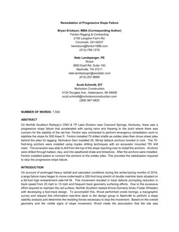
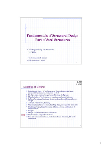
LATERAL PRESSURES ON SHEET PILE WALLSEARTH PRESSURE THEORIESEarth pressure is the force per unit area exerted by the soil on the sheet pile structure.The magnitude of the earth pressure depends upon the physical properties of the soil, theinteraction at the soil-structure interface and the magnitude and character of thedeformations in the soil-structure system. Earth pressure is also influenced by thetime-dependent nature of soil strength, which varies due to creep effects and chemicalchanges in the soil.Earth pressure against a sheet pile structure is not a unique function for each soil, butrather a function of the soil-structure system. Accordingly, movements of the structureare a primary factor in developing earth pressures. The problem, therefore, is highlyindeterminate.Two stages of stress in the soil are of particular interest in the design of sheet pilestructures, namely the active and-passive states. When a vertical plane, such as a flexibleretaining wall, deflects under the action of lateral earth pressure, each element of soiladjacent to the wall expands laterally, mobilizing shear resistance in the soil and causing acorresponding reduction in the lateral earth pressure. One might say that the soil tends tohold itself up by its boot straps; that is, by its inherent shear strength. The lowest state oflateral stress, which is produced when the full strength of the soil is activated (a state ofshear failure exists), is called the active state. The active state accompanies outwardmovement of the wall. On the other hand, if the vertical plane moves toward the soil,such as the lower embedded portion of a sheet pile wall, lateral pressure will increase asthe shearing resistance of the soil is mobilized. When the full strength of the soil ismobilized, the passive state of stress exists. Passive stress tends to resist wall movementsand failure.There are two well-known classical earth pressure theories; the Rankine Theory and theCoulomb Theory. Each furnishes expressions for active and passive pressures for a soilmass at the state of failure.Rankine Theory - The Rankine Theory is based on the assumption that the wallintroduces no changes in the shearing stresses at the surface of contact between the walland the soil. It is also assumed that the ground surface is a straight line (horizontal orsloping surface) and that a plane failure surface develops.When the Rankine state of failure has been reached, active and passive failure zoneswill develop as shown in Figure 1.PASSIVE CASEACTIVE CASEwhere angle of internal friction of soil (degrees)Fig. 1 - Rankine failure zones
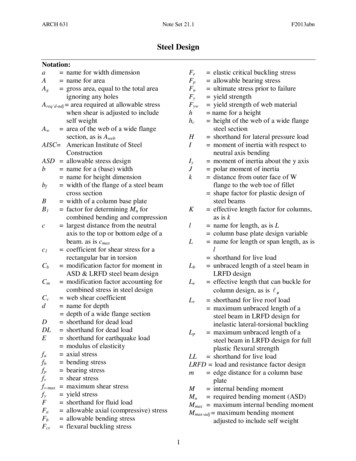
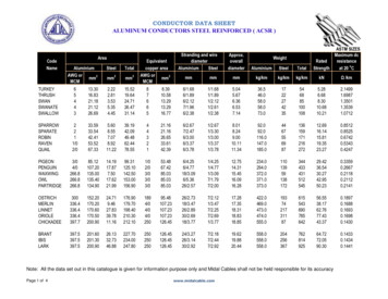
The active and passive earth pressures for these states are expressed by the followingequations:whereandand unit active and passive earth pressure, respectively, at adepth Z below the ground surface vertical pressure at a depth Z due to the weight of soilabove, using submerged weight for the soil below groundwater level unit cohesive strength of soil coefficients of active and passive earth pressures, respectivelyThe coefficients Ka and Kp, according to the Rankine Theory, are functions of the-angle of the soil and the slope of the backfill, . They are given by the expressionsNote that for the case of a level backfill, these equations reduce toThe triangular pressure distributions for a level backfill are shown in Figure 2. For variousslope conditions, refer to Mechanics of Soils by A. Jumikis.16(a)Granular SoilLevel BackfillGranular SoilSloping Backfill1Fig. 2 - Rankine earth pressure (after Teng )
Cohesive Soil - Active PressureCohesive Soil - Passive PressureFig. 2 - (Continued)Coulomb Theory - An inherent assumption of the Rankine Theory is that the presenceof the wall does not affect the shearing stresses at the surface of wall contact. However,since the friction between the retaining wall and the soil has a significant effect on thevertical shear stresses in the soil, the lateral stresses on the wall are actually different thanthose assumed by the Rankine Theory. Most of this error can be avoided by using theCoulomb Theory, which considers the changes in tangential stress along the contactsurface due to wall friction.As the wall yields, the failure wedge tends to move downward for the active case. Forthe passive case, where the wall is forced against the soil, the wedge slides upward alongthe failure plane. These differential movements involve vertical displacements betweenthe wall and backfill and create tangential stresses on the back of the wall due to soilfriction and adhesion. The resulting force on the wall is, therefore, inclined at an angle tothe normal to the wall. This angle is known as the angle of wall friction,For the activecase, when the active wedge slides downward relative to the wall, is taken as positive.For the passive case, when the passive wedge slides upward relative to the wall,is takenas negative. If the angle of wall friction is known, the following analytical expressions forKa and Kp in the horizontal direction for a vertical wall are:where angle of internal friction of soil angle of wall friction angle of the backfill with respect to horizontalFigure 3(a) is included for ease in obtainingandAs in the Rankine Theory, the Coulomb Theory also assumes a plane surface of failure.However, the position of the failure plane is a function of both the-angle of the soil andthe angle of wall friction,The position of the failure plane for the active and passivecases for a level backfill is given by:
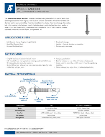
0103040ANGLE OF INTERNAL FRICTION,IN DEGREES2050Fig. 3(a) - Coulomb earth pressure coefficient vs. -angle for level backfill and dredge linewhereand angle between the failure plane and the vertical for theactive and passive cases, respectivelyFigure 3(b) shows the Coulomb active and passive failure wedges together with theCorresponding pressure distributions.8
ACTIVEFig. 3 (b) - Coulomb earth pressureFor a smooth wall (zero wall friction) with level backfill or ifthe Rankine and Coulomb Theories give identical results. for a sloping backfill,Log-Spiral Theory - The Coulomb Theory of earth pressure assumes that the surfaceof sliding or failure is a plane. This assumption deviates somewhat from reality. For theactive case the error introduced is small. However, for the passive case the error can belarge and is always on the unsafe side. If the angle of wall friction, , is low the failuresurface is almost plane. However, ifis high, the passive failure plane deviatesconsiderably from Coulomb’s assumption, which predicts unrealistically high passivepressures. Large angles of wall friction that cause a downward tangential shearing forcewill increase the vertical pressures in the soil close to the wall, thus causing a curvedfailure surface as shown in Figure 4(a). The soil fails on this curved surface of leastresistance and not on the Coulomb plane, which would require a greater lateral drivingforce. Figure 4(b) shows the reduction in the passive earth pressure coefficient, Kp, forincreasing values of wall friction for the actual curved surface of failure.(a)Fig. 4 - Comparison of Coulomb and log-spiral failure surface (after Terzahgi22)The method of computing earth pressures for a log-spiral failure surface is summarized inSoil Mechanics in Engineering Practice by Terzaghi and Peck. Table 1 lists values ofpassive lateral earth pressure coefficients for a curved surface of failure and level backfillfor various relative values of the angle of internal friction, , and the angle of wallfriction, The charts in Figure 5(a) give the active and passive coefficients for a log-spiralfailure surface for the case of wall friction and sloping backfill.1.651.892.19 2.553.01 4 . 2 9 6.42 10.20 17.501.561.761.98 2.252.59 3.46 4.781.421.551.70 1.85 2 . 0 4 2.46 3.003.704.600 . 6 4 0.610.530.520.73 0.680.58 0 . 5 5 0 . 5 36 . 8 8 10.38Table 1. Values of Passive Lateral-earth-pressureCoefficients(Curved Surfaces of Failure)(after Caquot and Kerise121)9
01020ANGLE OF INTERNAL FRICTION304045, DEGREESFig. 5(a) - Active and passive coefficients with wall friction (sloping backfill) (after Caquot and Kerisel21)10
Conditions:Broken Slope BackfillIrregular SurchargeWall Friction IncludedSloping Ground Water LevelLayered Soil.11Fig. 5(b) - Generalized determination of active pressures (after Navdock )11Fig. 5(c) - Generalized determination of passive pressures (after Navdock )In summary for the determination of lateral earth pressures on sheet pile walls:1.2.3.Active pressures should be computed using the Coulomb Theory or thelogarithmic spiral method as shown in Figure 5(a).Passive pressures should be computed using the Coulomb Theory with anappropriate safety factor or the logarithmic spiral method as shown in Figure5(a).For ‘complicated cross sections involving irregular and stratified backfills, thereader should consult such texts as Fundamentals of Soil Mechanics by Taylorand Soil Mechanics in Engineering Practice by Terzaghi and Peck. A graphicalanalysis for complicated cross sections is shown on Figures 5(b) and 5(c).11
Soil Properties - Independent of the theory used to compute earth pressure onretaining structures, the results can be no more accurate than the soil properties used inthe calculations. Because of the wide variations of subsurface conditions at various sites,the soil constants should be determined on the basis of an exploratory boring programand laboratory tests of representative samples. Only then can a safe and economicaldesign be assured. However, for the purpose of preliminary design it is often necessary topresume appropriate soil properties. The following tables and graphs are included for thispurpose merely as a guide.Table 2 shows an approximate relationship between the relative density, standardpenetration resistance, angle of internal friction, and unit weight of granular soils.CompactnessVery LooseLoose MediumDenseVery DenseRelative density D dStandard penetration resistance,N no. of blowsper foot(degrees) *Unit weight, pcfmoistsubmerged*highly dependent on gradationTable 2 - Granular soil (after Teng 1)Table 3 shows an approximate relationship between the unconfined compressivestrength, standard penetration resistance and the unit weight of cohesive soils.ConsistencyVery SoftSoftMediumStiffVery StiffHard unconfinedcompressionstrength, tonsper square ftStandard penetration resistance,N no. of blowsper ftUnit weight, rombetweenfingerswhensqueezedin handMoldedby lightfingerpressureMoldedIndentedby strong by thumbfingerpressure1Table 3 - Cohesive soil (after Teng )12Indented Difficultby thumb to indentnailby thumbnail
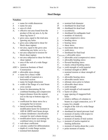
Figure 6 shows the approximate relationship between the angle of internal friction andthe dry unit weight for various relative densities and types of granular soils. The porosity,n, and the void ratio, e, are also shown for coarse grained soils that have a specific gravity,G, equal to 2.68.ANGLE OF INTERNAL FRICTIONVS. DRY UNIT WEIGHT(FOR COARSE GRAINED SOILS)OBTAINED FROMEFFECTIVE STRESSFAILURE ENVELOPES.APPROXIMATE CORRELATIONIS FOR COHESIONLESSMATERIALS WITHOUTPLASTIC FINES.DRY UNIT WEIGHT,PCFFig. 6 - Granular soils (after Navdocks11)Table 4 shows friction angles for various soils against steel sheet piles.Steel sheet piles against the following soils:Clean gravel, gravel-sand mixtures, well-graded rock fill with spalls .Clean sand, silty sand-gravel mixture, single size hard rock fill .Silty sand, gravel or sand mixed with silt or clay .Fine sandy silt, non-plastic silt .0.400.300.250.2022171411Table 4 - Wall friction (after Navdocks 11 )As mentioned previously, earth pressure is time-dependent in nature. This is particularlytrue in clay and clayey soils where the values of cohesion, c, and internal friction, , tendto change with time. Sheet pile structures in clayey soils should be designed for both theperiod immediately after construction and long term conditions. Limited informationindicates that due to creep effects the long term value of c approaches zero and that ofsomewhere between 20 and 30 degrees. The long term case thus approaches that for sheetpiling in granular soils.13
SURCHARGE LOADSThe function of a sheet pile structure is often to retain various surface loadings as well asthe soil behind it. These surface loads, or surcharge, also exert lateral pressures on thewall which contribute to the active pressure tending to move the wall outward. Typicalsurcharge loadings are railroads, highways, buildings, ore piles, cranes, etc.The loading cases of particular interest in the determination of lateral soil pressuresare:1.Uniform Surcharge2.Point LoadsLine Loads Parallel to the Wall3.4.Strip Loads Parallel to the WallFor the case of a uniform surcharge loading, the conventional theories of earth pressurecan be effectively utilized. On the other hand, for point, line and strip loads the theory ofelasticity (Boussinesq Analysis) modified by experiment provides the most accuratesolutions. These solutions are summarized in Foundation Design by Wayne C. Teng1 and“Anchored Bulkheads” by Karl Terzaghi.22Uniform Surcharge - When a uniformly distributed surcharge is applied at the surface,the vertical pressures at all depths in the soil are increased equally. Without the surchargethe vertical pressure at any depth h would bewhereis the unit weight of the soil.When a surcharge of intensity q (force/area) is added, the vertical pressures at depth hbecomeThe lateral pressure,due to the uniform surcharge q, is equal to Kq, as shown inFigure 7 below.Fig. 7 - Lateral pressure due to uniform surchargeThe K value is either the active coefficient Ka or the passive coefficient Kp dependingupon whether the wall tends to move away from or toward the surcharge area. Theuniform lateral pressure due to the surcharge is then added to the lateral dead weightearth pressures as described in previous sections.For the case of a uniform surcharge loading, lateral movement of the plane on whichthe horizontal stresses are being computed is taken into account by considering that theentire “active wedge” of soil is in a state of impending shear failure. On the other hand,computations of lateral stresses due to surcharge applied on a limited area (point, line andstrip loads) is complicated by the lack of a rational approach to the distribution of shearstresses in the soil adjacent a yielding vertical plane. Therefore, semi-empirical methods ofanalysis have been developed based upon elastic theory and experiments on rigidunyielding walls. The lateral pressures computed by these methods are conservative forsheet pile walls since, as the wall deflects, soil shear resistance is mobilized and the lateralpressure on the wall in reduced.
Point Loads - The lateral pressure distribution on a vertical line closest to a point loadmay be calculated as shown in Figure 8(a).Fig. 8(a) - Lateral pressure due to point load (after Terzaghi22)Away from the line closest to the point load the lateral stress decreases as shown in theplan view of Figure 8(b).Fig. 8(b) - Lateral pressure due to point load (Boussinesq equation modified by experiment)(after Terzaghi22)Line Loads - A continuous wall footing of narrow width or similar load parallel to aretaining structure may be taken as a line load. For this case the lateral pressure increasesfrom zero at the ground surface to a maximum value at a given depth and graduallydiminishes at greater depths. The lateral pressure distribution on a vertical plane parallelto a line load may be calculated as shown in Figure 9.15
Elevation ViewFig. 9 - Lateral pressure due to line load (Boussinesq equation modified by experiment) (after Terzaghi22)Strip Loads - Highways and railroads are examples of strip loads. When they areparallel to a sheet pile wall, the lateral pressure distribution on the wall may be calculatedas shown in Figure 10.Fig. 10 - Lateral pressure due to strip load (Boussinesq equation modified by experiment) (after Teng1)Based on the relationships given above, Figure 11 shows plots of the lateral pressuredistributions under point and line loads and gives the positions of the resultant force forvarious values of the parameter m.Line LoadsPoint LoadsFig. 11 - Horizontal pressures due to point and line loads (after Navdocks11)
EFFECTS OF UNBALANCED HYDROSTATIC AND SEEPAGE FORCESSheet pile structures built today in connection with waterfront facilities are subjected tomaximum earth pressure when the tide or river level is at its lowest stage. A receding tide,receding high water, or heavy rainstorm may cause a higher water level behind a sheet pilewall than in front of it, depending on the type of backfill used. If the backfill is fine orsilty sand, the height of water behind the sheet pile wall may be several feet. If the soilbehind the wall is silt or clay, full hydrostatic pressure in back of the wall should be assumed up to the highest position of the previous water level.The difference in water level on either side of the wall introduces (1) additionalpressure on the back of the wall due to hydrostatic load and (2) reduction in the unitweight of the soil in front of the piling (thus, a reduction of passive resistance). Thedistribution of the unbalanced water pressure on the two faces of the structurecorresponding to a hydraulic head, HU, can be determined by means of the flow netmethod as illustrated in Figure 12(a). If a sheet. pile structure is driven in granular soilwith fairly uniform permeability, the unbalanced water pressure may be approximated bythe trapezoid in Figure 12(b). If the permeability of the soil varies greatly in the verticaldirection, a flow net should be used to determine the unbalanced pressure.Fig. 12 - Hydrostatic and seepage pressures (after Terzaghi22)The upward seepage pressure exerted by the rising ground water in front of the outerface of a sheet pile wall reduces the submerged unit weight in front of the wall byapproximately the amount:where reduction in submerged unit weight of soil, pcf.Hence, the effective unit weight to be used in the computation of passive pressure iswhereH u unbalanced water head, feetD as shown in Figure 12The relationship betweenand HU/D is given in Figure 13.Fig. 13 - Average reduction of effective unit weight of passive wedge due to seepage pressure exertedby the upward flow of water (after Terzaghi22)17
The effect of downward seepage in the soil behind the piling is very small and may beneglected.It must be anticipated that some seepage will occur through interlocks, although theamount is difficult to predict. As an approximation, the seepage should be assumed toequal at least 0.025 gallons per minute per square foot of wall per foot of net head acrossthe wall for installations in moderately to highly permeable soils.OTHER LATERAL LOADSIn addition to the lateral pressures described previously, sheet pile structures may besubjected to some of the lateral loads described below.Ice Thrust - Lateral thrusts can be caused by the volume expansion of ice infine-grained soils (very fine sand, silt and clay). The possibility of lateral thrust from iceor frozen grou
Steel Sheet Piling Design Manual Notice "The information, including technical and engineering data, figures, tables, designs, drawings, details, suggested procedures, and suggested specifications,