Transcription
24TH INTERNATIONAL CONGRESS OF THE AERONAUTICAL SCIENCESCONCURRENT ENGINEERING DEVELOPMENT ANDPRACTICES FOR AIRCRAFT DESIGN AT AIRBUSThierry PardessusAirbus, Vice President Design Methods and DeploymentKeywords: concurrent engineering, processes, methods, design, aeronauticsAbstractReduction of cycles (development time, serieslead time) and costs along the aircraft lifecycleis a permanent priority. Concurrent engineeringaims at enabling this reduction, by puttingtogether in a multidisciplinary way of workingall the relevant skills contributing to productengineering, and by setting and managing theoperational conditions for work in parallel.It is mainly a question of processes and wayof working. For maximum business benefit, itsimplementation requires a strong sponsorship attop level, and discipline throughout theorganizations, in order to define and fully applycommon processes and common methods,supported by common tools.The Digital Mock-up (DMU) becomes theheart of the product information. It is createdwith the support of Computer Aided Design(CAD) and is managed by a Product DataManagement (PDM) system that also supportsthe industrial drawing release process andconfiguration ing lead to significant businessbenefits, which can be measured in terms oflead-time and reduction of effort indevelopment. These benefits have now beenmade visible for the development of the A340500 and A340-600, and for the A380.As a vision, Airbus expects furtherintegration steps in the design office technology,targeting a Virtual Aircraft, with stronger linksbetween Systems Engineering (includingArchitectural Design and Requirement BasedEngineering), Design to Decision Objectivesaround the DMU, and supported by the PDM.1Business context and programmesrequirements1.1About large aircraftA completed commercial aircraft is inmany ways the compromise of the knowledge,experience and creativity of the numerousengineers involved in an aircraft manufacturers‘multidisciplinary design and productiongroups. But it must be also essentially the smartresponse to requirements coming from evermore demanding Customers, as well as fromairworthiness authorities. These requirementscover safety, product aircraft performance andoperational characteristics, customization, andassociated response time, acquisition costs,operating and maintenance costs, environmentalrequirements, and others. From the businessside, competition isfierce, and Airbus’approach is to offer permanently world classproducts and services which set the industry’sstandards.Just to fix the ideas the definition of theA380 is composed of a set of about 1 000 000drawings, which is dramatically much biggerthan the number of drawings of the A340. Thefunctional architecture of the systems is brokendown into about 70 major systems, leading toseveral hundreds of pieces of equipment. Allthese definition information and data have to bemanaged carefully to ensure full traceability ofthe definition of a given aircraft against itscustomer’s contractual requirements. This is theobjective of configuration management.1
Th. PardessusThe size and complexity of the product hasled Airbus since the beginning to define andimplement an industrial work sharing foraircraft development and series production. Thishas led to a high industrial specialization, withlocal processes sometimes, which have hadrecently to be harmonized to a wide extent.1.2 Development costs and design processesWhen developing a new product, the wellknown comparison of the costs committed bythe definition progress versus actual costs at anytime clearly shows the necessity to drasticallyimprove at the earliest the best knowledge wecan have about the complete product to bedeveloped and delivered. In the mean time,reduction of development cycle and productioncycle is absolutely mandatory, to deliver betterresponse time to market and reduce final cost ofthe product.Two main features can characterize designengineering processes: In upstream phases (concept, feasibility,preliminary definition), processes are highlyinteractive and iterative. Degrees offreedom are numerous, and must bemanaged carefully in order not to be frozentoo early. Work is mainly focused onarchitectural level, and trade-offs arefrequent with a high impact on theconfiguration. Trade-offs between aircraftconfiguration and the overall design of maincomponents are frequent. Work force inthese phases is still limited (compared to thewhole development workload). In the development phase, degrees offreedom are limited to very local design,industrialperformance(linkofengineering to manufacturing) is paramount,deployed workforce is huge to produce thedefinition and industrialize the product,sensitivity to operational configurationmanagement increases dramatically.One of the key conditions to reach cost and timereductions is to ensure that alization), then series production phases,are performed with maximum efficiency. Thisleads also to make sure that the concept andfeasibility phases, in which the large trade-offsare performed in a rather iterative manner,deliver sound baselines. As far as a designchange is concerned during the developmentphase, the later it occurs, the more expensive itwill be. Consequently, all disciplines mustinteract in an efficient manner, with a commonobjective, the successful and efficientdevelopment of the aircraft.2Concurrent Engineering approach2.1FundamentalsThe main concepts supporting ConcurrentEngineering are: Managing complexity of the product inmaking it accessible to each team, then toeach individual in the team. This leads tobreak down the product into certain“concurrent engineering products” orbusiness objects, which represent designdomains (geometrical, functional), andwhich enable to maximize the work inparallel. Synchronization, to ensure that the resultingdevelopment cycle is under control. Control of interfaces of the different designdomains. Multidisciplinary engineering. “Break the walls”, especially by developingcollaborative techniques throughout theextended enterprise. Permanenttraceabilityofproductconfiguration information. Think process, then method and then tool.This process based paradigm implies:1. to really consider how design teamsactually cooperate in design context,what business objects they use, how theyshare them, how these objects evolve asdesign evolves or when change occurs.2. to think as much as possible in terms ofprocess integration, to streamline theoverall workflow, and to maximizeprocess quality.2
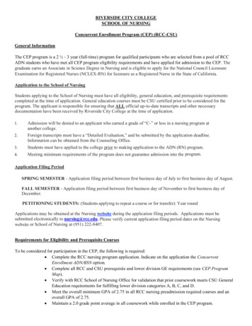
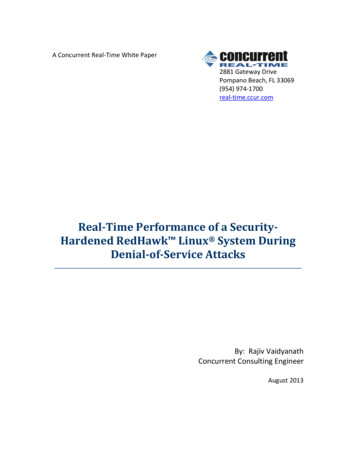
CONCURRENT ENGINEERING DEVELOPMENT AND PRACTICESFOR AIRCRAFT DESIGN AT AIRBUSAirbus has been widely investing in thedevelopment and deployment of concurrentengineering capabilities. The project, known asACE ( Airbus Concurrent Engineering), is nowa key integrator, as well as a strong vehicle ofchange management.Through the significant reduction of the leadtime, concurrent engineering leads to significantcost reduction. Also, the need to share a lot ofinformation and data with numerous users fromdifferent skills has induced the implementationof strong structuring concepts.2.2Synchronization through commonvisible milestonesA common and structured development cycle,has been developed. It is now the baseline forall Airbus programmes.‘Fig.1. A common view of developmentmilestones’drawings has to be produced and delivered,when tooling has to be designed andmanufactured.Each milestone is described in terms ofexpected engineering content, and thus theengineering work is specified in a visible andshareable manner. Even though in the actualimplementation there can be some tuning (dueto programme specifics), this gives a strongframework for development organization, workstructure, and planning.2.3 The Digital Mock-Up (DMU)Practically, even if it does require newgenerationpowerfultools,concurrentengineering is not just a tool problem: it isfirstly a question of technical processes andwork organization, from which dedicatedmethods and tools have to be developed.‘Fig.2. DMU’The Digital Mock-Up (DMU) enables Design &Configuration ManagementA common view of development milestonesM3FEASABILITYOrderreleasedfor projectM1y ndM0ProductideaestablishedInstructionto proceed(ITP)M5CONCEPTInstructionto proceed(ITP)M3M524th ICAS Congress- eM7M13DEFINITIONDefinitionof M10Power on SERIESBeginfinalassemblyM8M6Authorisation First metalcuttooffer (ATO)3D PartsM12M14TypeEndcertification developmentphasefor basicaircraftThe Digital Mock-Up is defined by Parts designed in 3D andpositioned in the Space, managed by the PDMStrong Link between Geometry and Aircraft ConfigurationManagement24th ICAS Congress - Yokohama6 Tree Structure9 Arborescence (breakdown)9 Positioning of the 3D Parts AIRBUS S.A.S. All rights reserved. Confidential and proprietary document.Definitionof basicconcept8Page 8Page 6This common development model is brokendown into five major phases: Feasibility (M0 – M3). Concept (M3 – M5). Definition (M5 – M7). Development (M7 – M13). Series (M13 – M14).Typically, in a programme, the ramp-up ofresources takes place after M5, and even moresignificantly after M6, when the complete set ofAs already mentioned, concurrent engineeringmeans that design engineering teams areworking in parallel. This makes sense only ifthey know at each time the status of the productthey are working on, which means to enable asharing of the information, according to thedifferent needs of the users.3
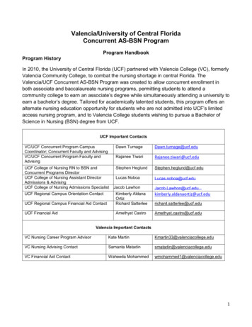
Th. PardessusThe DMU is composed of several designproducts: each of these products is used tosatisfy the engineering expectations of thedifferent teams along the product lifecycle. Forinstance: The Master Geometry resulting mainlyfrom the definition of the aerodynamicshape of the aircraft can be used by thestructure design team to derive a preliminarydefinition of the structure and associateddesign principles, by the manufacturingengineering teams to have a preliminarydefinition of the final assembly lineoperations and building, and by theoperations engineering teams to study theservicing capability at the airport. The Space Allocation Model enables thesystems engineering teams to perform thepre-installation of systems and variouspieces of equipment. It also enables thedesign supportability teams to assess howthe maintenance operations can beperformed.Eventually, the Definition Model is thefinal stage of the DMU, from which the datafor manufacturing is derived.Some of the other DMU products are: theDesign Principles, the Frontier Models, theStressDesignReferenceBase,theSystems/Equipment Installation RequirementsDossier.The concepts of Master Geometry and SpaceAllocation Model also apply to tooling.The DMU is now the central tool betweenthe different engineering teams, and also afundamental dialog tool between Engineeringand Manufacturing.‘Fig.3. Development process’The development process involves several TIONM13DEVELOPMENTSERIESAircraftIntegrated Project Teams (Plateau)Support IndustrializationThe DMU is consequently defined as anorganized set of information, reflecting thedifferent needs of the design teams, andstructured according to a Product Structure.The Product Structure is mainly the corestructure describing and managing how thedrawing sets (when considering the output formanufacturing) are organized. It is also one ofthe key enablers of Configuration Management.From a technology perspective, the DMU relieson techniques similar to Virtual Reality. Thus itis possible to “navigate” in the DMU, to exploreselected design areas. AIRBUS S.A.S. All rights reserved. Confidential and proprietary document.It also appeared quickly that this approach led todefine several “design products” representingthe aircraft; these design products being actuallylarge information objects. One can also considereach of these design products as one perspectiveor point of view relevant to certain needs. Andsince the objective of design engineering ismainly to produce data for manufacturing, thispackage of design information is called DigitalMock-Up (DMU).MasterMaster GeometryGeometryDesignDesign PrinciplesPrinciplesSIRDSIRD EIRDEIRDSpaceSpace AllocationAllocationStressStress DesignDesign ReferenceReference BaseBaseFrontierFrontier ModelsModelsDefinition DossierToolingTooling MasterMaster GeometryGeometry PrinciplesPrinciplesToolingTooling SpaceSpace AllocatiAllocati ToolingTooling ModelModelToolingTooling FrontierFrontier ModelsModelsManufacturingManufacturing PlanPlanNCNC ProgramsProgramsSupportSupport SpecificationSpecificationInstructionsInstructions SheetsSheetsSupportabilitySupportability AnalysisAnalysisSupportabilitySupportability DiscrepanciesDiscrepanciesMock-ups are Key Integration Elements24th ICAS Congress - Yokohama2.4DefinitionDefinition ModelModel10Page 10Way of working, new jobs2.4.1 Working around the DMUAs a consequence, concurrent engineeringhas placed the DMU at the heart of the technicalquality of the design process. It has beennecessary to establish around the DMU theappropriate technical control processes. This ismainly achieved through the DMU reviews.Held at regular time periods, the DMU reviewsallow progressive validation of the productdesign thanks to the participation of themultidisciplinary teams.4
CONCURRENT ENGINEERING DEVELOPMENT AND PRACTICESFOR AIRCRAFT DESIGN AT AIRBUSIt is a strong contribution to the businessrequirement to get it right first time. Using theDMU enables also to suppress the developmentand use of expensive (in time and cost) physicalmock-ups.2.4.2 DMU integrators, DMU Data QualityThe DMU is quite a complex engineeringobject, and requires proper management.Otherwise all benefits of concurrent engineeringare lost, there is a risk of more manual work(and hence limited cost reduction, risk not tomeet programme milestones), or even worseloss of baseline.Therefore Airbus has defined andimplemented the skill of “DMU integrators”.In each component design and build team thereis now one or several DMU Integrator(s), whosejob is mainly: To ensure the validity of the data composingthe DMU, especially those related toconfiguration. To perform problem analysis and ensure thecorrectness of the DMU (especially afterintegration phases), e.g. to check that thereis no “hole”, no erratic data, to identify thefirst clashes. Hence, to contribute to design processquality.Airbus has consequently also defined andimplemented a new skill: DMU Data QualityManagement.2.4.3 Development plateausImplementation of concurrent engineering hasled to organize the design teams in plateaus. Inthe plateau concept, teams from different CustomerServices,Procurement ) are co-located in propercollaborative environment for rapid andefficient communication and decision-making.Every involved discipline is the carrier ofhis/her home competence, and the validationand decision-making process is properlydefined. The plateau is also the place whereduring the definition phase of a programme,risk-sharing subcontractors are co-located withAirbus teams to optimize the specification oftheir work package.3Key enabling technology: ComputerAided Design (CAD), Product DataManagement (PDM)3.1Computer Aided Design (CAD)The CAD technology now enables us tosupport a complete product process from thefirst pre-design concepts in the design office tothe detailed programming of the numericalcontrolled machine for the manufacture of basicparts. This leads to the concept of IntegratedTechnological Process (ITP).Designing in 3D is not only managing puregeometries. It is mainly the way to ensure thatthe parts are designed as a whole, in a holisticapproach, integrating and managing functionalrequirements or constraints (e.g. interfaces,holes, clearance requirements, parametricdefinition).Knowledge Based Engineering (KBE)applications: embedding more knowledge (andmanaging this knowledge in configuration) intothe CAD system, and hence creating a seamlessCAD KBE package, delivers more and morecollective benefit, and contributes to industrialprocesses quality.ITPs can be envisaged for all product/partfamilies of an aircraft, such as: sheet metal,machined parts, composites, piping, tubing, andelectricity.It is not the intent of this paper to detailCAD technology, since numerous referencesaddress the matter.3.2Product Data Management (PDM)The PDM is the operational and neuralgicengine of the aircraft development anddefinition. It enables especially: At DMU level: The management of the productstructure (that is the way the set of5
Th. Pardessus 4drawings is organized and how thedrawings are released to manufacturing). The vaulting of design data. The integration of the DMU. The visualization of the completeproduct DMU according to its actualconfiguration status. The access by the design teams,provided appropriate authorizations(particularly in case of the extendedenterprise) and subscriptions are defined,to the DMU.At industrial process level: The management of the change process(either during a development phase or ina customization phase). The validation and application of cordingtothecustomers’ requirements. The link with the Enterprise ResourcePlanning system.Concurrent Engineering implementation4.1 From theory to practiceDeveloping and implementing concurrentengineering techniques is not a minor task. It isa deep change, impacting several operationalfunctions of the company. Like any other highadded value developed product, concurrentengineering capabilities deliverables mustabsolutely be thought as “users oriented”.4.1.1 Overall approachThe overall implementation approachconsiders the following phases: development,deployment, and operations.These phases are not sequential andthemselves obey concurrent engineeringprinciples! Development and deployment are instrong interaction. Deployment and operationshave to be smoothly managed to avoid anyhandover transition problem.4.1.1.1 DevelopmentDuring the development phase, users’ needs arecaptured, processes re-engineered, as far asneeded, these needs are transformed intocapabilities specifications, and the tool relatedparts are transformed into software/hardwarespecifications, which are then developed andtested.4.1.1.2 DeploymentThe deployment phase consists in making thecapabilities available to their users, after havingverified the specifications, tested in actualoperational environment, ensured training ofusers,ensuringthefirstoperationalaccompaniment in support to the users.Deployingconcurrentengineeringcapabilities is subject to the definition ofdeployment roadmaps, in order to take intoaccount: The current “equipment” of teams(currentlyoperationalconcurrentengineering packages, information systemand IT environment). The necessary level and quantity oftraining. The business context, and its suitability orcriticality to experience a migration. The costs and scheduling of deployment.4.1.1.3 OperationsWhen the capabilities are deployed, the designteams on the plateaus have to operate with theDMU. They are supported by CAD/PDMsupport teams, very close to the users (by theirknowledge of design processes, by theirphysical collocation on the plateau). It isgenerally considered reasonable to have onesupport head per fifty design heads in steadyregime. Learning phases induce alities are deployed) to a higher ratio.4.1.2Implementation and uired:implementing concurrent engineering (even for6
CONCURRENT ENGINEERING DEVELOPMENT AND PRACTICESFOR AIRCRAFT DESIGN AT AIRBUSorganizations
engineering capabilities. The project, known as ACE ( Airbus Concurrent Engineering), is now a key integrator, as well as a strong vehicle of change management. Through the significant reduction of the lead-time, concurrent engineering leads to significant cost reduction. Also, the need