Transcription
Phase2Trade of Motor MechanicModule 2Unit 4Alternator/Circuit
Produced byIn cooperation with:Subject Matter ExpertsMartin McMahon&CDX GlobalCurriculum Revision 2.2 16-01-07 SOLAS 2013
Module 2 - Unit 4Alternator/CircuitTable of ContentsIntroduction. 1Unit Objective. 21.0Hazards when Working Charging Systems. 31.1Hazards when Working Charging Systems. 32.0Electrical Loads. 42.1Alternator Loads. 43.0Current Load Manufacturers Data. 64.0Diagram of the Charging System. 64.1Schematic Block Diagrams. 65.0Function of the Alternator. 85.1Charging System. 85.2Alternator Principles. 96.0Faraday's Conclusion on Electromagnetic Induction. 116.1Faraday’s Laws and Fleming’s Right Hand Rule. 117.0Testing a Battery Using a Voltmeter.137.1Checking a Charging System.137.2Using a DVOM to Measure Voltages.158.0Circuit Continuity Testing on the Alternator Wiring.179.0Voltage Drop Testing on the Alternator Output Lead.179.1Voltage Drop Test.1710.0 Alternator Brush and Voltage Regulator Examination.1811.0 Servicing an Alternator Drive Belt.1811.1 Inspecting & Adjusting an Engine Drive Belt.1811.2 Replacing an Engine Drive Belt. 23Self Assessment. 27Task Sheets. 30Checking a Charging System. 30Removing & Replacing an Alternator. 32Inspecting & Adjusting an Engine Drive Belt. 35Replacing an Engine Drive Belt. 40Suggested Further Reading. 44Trade of Motor Mechanic - Phase 2 Course NotesRevision 3.0 November 2013
Module 2 - Unit 4Alternator/CircuitIntroductionThere are six Units in this Module. In Theory 1 we cover Units 1,2 and 3 which focuses on the basics of electricity. In Theory 2 wecover Units 4, 5 and 6 which focuses on the fundamental electricalcircuits in the vehicle.Module 2BodyElectricsUnit 4Alternator/CircuitUnit 5Starter Motor/CircuitUnit 6Body WiringLighting CircuitsIn this Unit four it describes the basic function and operation of thealternator and related circuits. You will receive instruction on howLocate and calculate the total current load of the primary, constant,long time, short time consumers of a vehicle and compare theseto the manufacturer's specifications. Draw a basic schematic blockdiagram of the charging system and describe the basic function ofan alternator.With the use of a voltmeter be able to carry out a basic chargingsystem test underload and off load.Carry out circuit continuity tests on the alternator wiring. Carryout a voltage drop test on the alternator output lead. Remove andexamine for wear alternator brushes and check the voltage regulatorassembly. Check and replace the alternator belt. Be made aware ofthe danger of working with running alternator pulleys, belts etc.and the damage to vehicle electronic circuit components by arcing/voltage peaks. Health and safety issues related to this unit will alsobe covered.Trade of Motor Mechanic - Phase 2 Course Notes1Revision 3.0 November 2013
Module 2 - Unit 4Alternator/CircuitUnit ObjectiveBy the end of this unit each apprentice will be able to: State the primary, constant, long time and short time electricalloads in the petrol/diesel engined automobile Locate and calculate the total current load of the primary,constant, long time, short time consumers of a vehicle andcompare to the manufacturer’s alternator specification Draw a basic schematic block diagram of the charging system(no alternator internal details) Describe the basic function of an alternator Describe Faraday’s conclusion on electromagnetic induction Use a Voltmeter across the battery to carry out a basic chargingsystem ‘voltage level underload/voltage level off load test’ Carry out circuit continuity tests on the alternator wiring ofan operational vehicle Carry out a voltage drop test on the alternator output lead ofan operational vehicle Remove, examine for wear and replace alternator brushes andvoltage regulator assembly Check/replace an alternator drive beltTrade of Motor Mechanic - Phase 2 Course Notes2Revision 3.0 November 2013
Module 2 - Unit 4Alternator/Circuit1.0 Hazards when WorkingCharging SystemsKey Learning Points 1.1Danger of working with running alternator pulleys, beltsetc. Damage to vehicle electronic circuit components byarcing/voltage peaksHazards when Working ChargingSystemsIt is important to be aware of the potential hazards when workingan automotive charging system. Remember that the alternator isdriven by a belt and the belt rotates very quickly when the engineis operating. Always ensure that you are aware of this when doingany work around the alternator when the engine is running (forinstance when checking alternator output). If anything you arewearing (including long hair gets caught in the rotating belt and othercomponents you could severely hurt yourself or even potentiallybe killed. There is also a danger of electronic components gettingdamaged from voltage peaks/arcing.Trade of Motor Mechanic - Phase 2 Course Notes3Revision 3.0 November 2013
Module 2 - Unit 4Alternator/Circuit2.0 Electrical LoadsKey Learning Points 2.1Constant loads e.g. ignition and fuel systems; long timeloads; lights etc.; short time, starter, glow plugs etc.Alternator LoadsCurrent Demand and FlowIf you have an alternator that can produce 120 amps of current(max) and the total current demand from the electrical accessories(including the battery) is only 20 amps, the alternator will onlyproduce the necessary current (20 amps) to maintain the targetvoltage (which is determined by the alternator's internal voltageregulator). Remember that the alternator monitors the electricalsystem's voltage. If the voltage starts to fall below the target voltage(approximately 13.8 volts depending on the alternator's design), thealternator produces more current to keep the voltage up. When thedemand for current is low, the full current capacity of the alternatoris not used/produced (a 120 amp alternator does not continuouslyproduce 120 amps unless there is a sufficient current draw). See thefollowing diagram for some of examples of current demand. Referto automotive technical manuals for more vehicle specific data.Trade of Motor Mechanic - Phase 2 Course Notes4Revision 3.0 November 2013
Module 2 - Unit 4Alternator/CircuitShort-term loadPermanent loadPer interior lamp5WIgnition20WPer flasher lamp(indicator)21WElectric fuel pump50–70W2 stop lamps42WElectronic petrolinjection70–100WPer reversing lamp 21WLong-term loadHorn25–40 W Car radio approx10–100WFog lampRear-windowwiper21WPer licence-plate lamp 10W30–65WSide lampWipers.80W2 headlamp dip lights 110WCigarette lighter100W120WRear-windowheater2 headlamp mainbeams120WPer rear tail light5W5WFor diesel carsHeater plugs forstarting (per cylinder)100WPower windows150WElectric radiator fan200WStarter800–3000wElectrical Consumer LoadsToday, most systems in the average vehicle such as power windows,power seats and power door locks are electrically powered. Typicalvalues for headlights would approx 10 amps and heater plugs wouldbe in excess of 50 amps. Initial current draw from the starter ona diesel engine is approximately 120 amps. Refer to automotivetechnical manuals for more vehicle specific dataOne constant and growing challenge is the average load of theautomotive electrical system, which is increasing and is beginningto exceed the limits of the 14-volt alternator, which typicallygenerates 150 amps to 180 amps. Increases the cable harness size,power distribution box complexity, the relay and switch rating alsoincreases.Trade of Motor Mechanic - Phase 2 Course Notes5Revision 3.0 November 2013
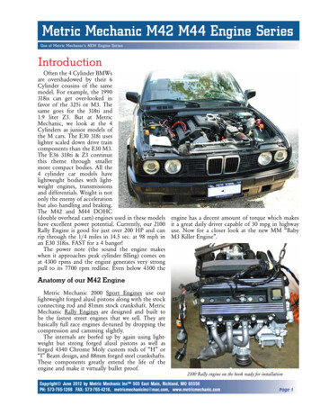
Module 2 - Unit 4Alternator/Circuit3.0 Current Load ManufacturersDataKey Learning PointsPractical Task Source manufacturer's data for current quantity/load valueof electrical systems Calculation of the total current requirement of S.I. /I.C.automotive VehicleThis is a practical task. Please refer to your instructor for additional information,which is available from the automotive technical manuals.4.0 Diagram of the ChargingSystemKey Learning Points 4.1Schematic block diagram drawn to industry standard i.e.correct terminal and component identification code/number/symbols used.Schematic Block DiagramsSee the following page.Trade of Motor Mechanic - Phase 2 Course Notes6Revision 3.0 November 2013
Module 2 - Unit 4Alternator/CircuitAlternator/Starter Motor- Wiring CircuitManufacturer:ComponentG1 AlternatorH1 Alternator warningEngine code:lampAFN31 Battery Tuned for:30 Batter Model: PassatA35 Engine control(96-00) D TDIOutput: 81 (110) moduleK270 Engine running4150circuits relayYear: 1996-00Reproduced courtesy 15 Ignition switch- ignition ONof Autodata 50 Ignition switchLimited, unit- start signal5 priors way,A35 Instrument panelmaidenhead,A75 InstrumentationEngland.control moduleM1 Starter motorVolkswagen Wiring colour Codesbl bluegn greenrs pinkws whitexbraided cablebr browngr greyrt redhbl light blueyhigh tensionel creamnf neutralsw blackhgn light greenznon-cableconnectionge yellowog orangevi violetrbr maroonRefer to Automotive technical manuals for these diagramsTrade of Motor Mechanic - Phase 2 Course Notes7Revision 3.0 November 2013
Module 2 - Unit 4Alternator/Circuit5.0 Function of the AlternatorKey Learning Points 5.1Alternator converting mechanical energy into electricalenergy Generating current to meet load demandCharging SystemThe charging system provides electrical energy for all of the electricalcomponents on the vehicle.The main parts of the charging system include, the battery, thealternator; the voltage regulator, which is usually integral to thealternator; a charge warning, or indicator light; and wiring thatcompletes the circuits.The battery provides the electrical energy for starting. Then, once theengine is running, the alternator supplies all electrical componentsof the vehicle. It also charges the battery to replace the energy usedto start the engine. The voltage regulator prevents over-charging.ConceptsIt is important to understand that the generator creates an electriccurrent, but does not create electric charge, which is already presentin the conductive wire of its windings. It is somewhat analogousto a water pump, which creates a flow of water but does not createthe water itself.Voltage regulation is the ability of a system to provide near constantvoltage over a wide range of load conditions.Trade of Motor Mechanic - Phase 2 Course Notes8Revision 3.0 November 2013
Module 2 - Unit 4Alternator/Circuit5.2Alternator PrinciplesThe alternator is universally used in automotive applications. Itconverts mechanical energy into electrical energy, by electromagnetic induction.In a simple version, a bar magnet rotates in an iron yoke whichconcentrates the magnetic field. A coil of wire is wound around thestem of the yoke. As the magnet turns, voltage is induced in thecoil, producing a current flow. When the North Pole is up and Southis down, voltage is induced in the coil, producing current flow inone direction.As the magnet rotates and the position of the poles reverses, thepolarity of the voltage reverses too and as a result, so does thedirection of current flow.Current that changes direction in this way is called alternatingcurrent, or AC. The change in direction occurs once for everycomplete revolution of the magnet.Trade of Motor Mechanic - Phase 2 Course Notes9Revision 3.0 November 2013
Module 2 - Unit 4Alternator/CircuitTheory of OperationAlternators generate electricity by the same principle as DCgenerators. When magnetic field lines cut across a conductor, acurrent is induced in the conductor. In general, an alternator hasa stationary part (stator) and a rotating part (rotor). The statorcontains windings of conductors and the rotor contains a movingmagnetic field. The field cuts across the conductors, generating anelectrical current, as the mechanical input causes the rotor to turn.Source: Volkswagen The rotor magnetic field may be produced by induction (in a“brushless” generator), by permanent magnets, or by a rotorwinding energized with direct current through slip rings and brushes.Automotive alternators invariably use brushes and slip rings, whichallows control of the alternator generated voltage by varying thecurrent in the rotor field winding. Permanent magnet machines avoidthe loss due to magnetizing current in the rotor but are restricted insize owing to the cost of the magnet material. Since the permanentmagnet field is constant, the terminal voltage varies directly with thespeed of the generator. Brushless AC generators are usually largermachines than those used in automotive applications.Trade of Motor Mechanic - Phase 2 Course Notes10Revision 3.0 November 2013
Module 2 - Unit 4Alternator/Circuit6.0 Faraday's Conclusion onElectromagnetic InductionKey Learning Points Faraday's conclusion of EMF induction Fleming's right-hand rule (dynamo rule)6.1Faraday’s Laws and Fleming’s RightHand RuleFaradays LawAny change in the magnetic environment of a coil of wire will causea voltage (emf - electro motive force) to be ‘induced’ in the coil. Nomatter how the change is produced, a voltage will be generated. Thechange could be produced by changing the magnetic field strength,moving a magnet toward or away from the coil, moving the coilinto or out of the magnetic field, rotating the coil relative to themagnet, etc.Electro Motive Force - EMFThe difference of potential produced by an electrical source to drivea current through an external electrical circuit. The SI unit of emfis the volt.Trade of Motor Mechanic - Phase 2 Course Notes11Revision 3.0 November 2013
Module 2 - Unit 4Alternator/CircuitFleming’s Right Hand RuleAlso known as the Generator Rule this is a way of determining thedirection of the induced emf of a conductor moving in a magneticfield.The thumb, the first and the second fingers on the right hand areheld so that they are at right angles to each other.If the first finger points in the direction of the magnetic field andthe thumb in the direction of the motion of the conductor thenthe second finger will point in the direction of the induced emf inthe conductor.Trade of Motor Mechanic - Phase 2 Course Notes12Revision 3.0 November 2013
Module 2 - Unit 4Alternator/Circuit7.0 Testing a Battery Using aVoltmeterKey Learning Points Correct use of the multimeter Charging system basic test; appropriate current loading used,voltage levels compared to manufacturer’s specifications7.1Practical TaskChecking a Charging SystemThis is a practical task. Please refer to your instructor for additional information,which is available from the automotive technical manuals.Preparation and SafetyObjectiveCheck a charging system.Safety Check Make sure the bonnet stay rod is secure. Always make sure that you wear the appropriate personalprotection equipment before starting the work. It is very easyto hurt yourself even when the most exhaustive protectionmeasures are taken. Always make sure that your work area/environment is as safeas you can make it. Do not use damaged, broken or worn outservice department equipment. Always follow any manufacturer's personal safety instructionsto prevent damage to the vehicle you are servicing.Trade of Motor Mechanic - Phase 2 Course Notes13Revision 3.0 November 2013
Module 2 - Unit 4Points to NoteAlternator/Circuit Make sure that you understand and observe all legislativeand personal safety procedures when carrying out thefollowing tasks. If you are unsure of what these are, ask yourinstructor. DVOM stands for Digital Volt Ohm Meter. DVOMs come in many forms. Always follow the manufacturer'sinstructions in the use of the meter, or you could seriouslydamage the meter or the electrical circuit.Step-by-Step Instruction1.Set up the meter for a voltage check: Prepare the Digital volt ohmmeter or DVOM for testing for voltage by inserting the blackprobe lead into the “common” input port and the red probelead into the “Volt/Ohms” input port.2.Check the meter function Turn the rotary dial until you haveselected the mode for “Volts DC”. The reading on the metershould now be at Zero. Some meters will automatically sensethe correct voltage range when a voltage is detected. On othermeters you will have to set the voltage range before using themeter.3.Check the battery voltage Place the Black probe onto the Negativeterminal of the battery, which will be marked with a Minussign and place the Red probe onto the Positive terminal ofthe battery. This is marked with a Plus sign. Note the voltagereading from the battery.4.Check the voltage after starting Start the engine. The voltagenow shown on the display should be within the 13.7 to 14.4Volt range when the engine is running at approximately2000RPM.5.Check the voltage with additional load With the engine still running,turn the headlights of the vehicle ON and note any differencesin the reading. The meter may “fluctuate” a little before settlingdown. Provided it retains a voltage reading within the originalspecifications, the voltage regulation side of the chargingsystem is operating correctly.Trade of Motor Mechanic - Phase 2 Course Notes14Revision 3.0 November 2013
Module 2 - Unit 4Alternator/Circuit7.2Using a DVOM to MeasureVoltagesPreparation and SafetyObjectiveUse a DVOM to measure voltage.Safety Check Make sure the bonnet stay rod is secure. Always make sure that you wear the appropriate personalprotection equipment before starting the job. It is very easyto hurt yourself even when the most exhaustive protectionmeasures are taken. Always make sure that your work area/environment is as safeas you can make it. Do not use damaged, broken or worn outworkshop equipment. Always follow any manufacturer's personal safety instructionsto prevent damage to the vehicle you are servicing. Make sure that you understand and observe all legislativeand personal safety procedures when carrying out thefollowing tasks. If you are unsure of what these are, ask yourInstructor. DVOM stands for Digital Volt Ohm Meter. DVOMs come in many forms. Always follow the specificmanufacturer's instructions in the use of the meter, or seriousdamage either to the meter and/or to the electrical circuitcould result.Points to NoteTrade of Motor Mechanic - Phase 2 Course Notes15Revision 3.0 November 2013
Module 2 - Unit 4Alternator/CircuitStep-by-Step Instruction1.Set up the meter for a voltage check: Prepare the Digital Volt OhmMeter or DVOM for testing voltage by inserting the blackprobe lead into the “common” input port and the red probelead into the “Volt/Ohms” input port.2.Check the meter function: Turn the rotary dial until you haveselected the mode for “Volts DC”. The reading on the metershould now be at Zero. Some meters will automatically sensethe correct voltage range when a voltage is detected. On othermeters you will have to set the voltage range before using themeter.3.Check the voltage of a battery: Place the Black probe onto theNegative terminal of the battery, which will be marked with aMinus sign and place the Red probe onto the Positive terminalof the battery, which is marked with a Plus sign.4.Interpret the results: Note the voltage reading from this 12-voltbattery. If the battery is fully charged the meter will give areading that is 12.6 volts or more. If it is NOT fully chargedthe reading will be less than 12.6 volts.Trade of Motor Mechanic - Phase 2 Course Notes16Revision 3.0 November 2013
Module 2 - Unit 4Alternator/Circuit8.0 Circuit Continuity Testing onthe Alternator WiringKey Learning Points Practical TaskContinuity test; cables removed correctly and secured freefrom shorts etc., voltage action/level compared to availablesystem voltageThis is a practical task. Please refer to your instructor for additional information,which is available from the automotive technical manuals.9.0 Voltage Drop Testing on theAlternator Output LeadKey Learning Points Practical TaskVoltage drop test; voltmeter between either end of 'underload' connector, voltage drop compared and interpreted tomanufacturer's recommended tolerancesThis is a practical task. Please refer to your instructor for additional information,which is available from the automotive technical manuals.9.1Voltage Drop TestA voltage drop test is the only effective way to find excessiveresistance in high amperage circuits. It's a quick and easy test thatdoesn't require any disassembly and will quickly show you whetheror not you've got a good connection or not.To do a voltage drop test, you create a load in the circuit that's beingtested i.e. output from alternator. Then you use a digital, volt andohm meter (DVOM) to measure the voltage drop across the liveconnection while it is under the load. Voltage always follows thepath of least resistance, so if the circuit or connection being testedhas too much resistance some of the voltage will flow through theDVOM and create a voltage reading.Trade of Motor Mechanic - Phase 2 Course Notes17Revision 3.0 November 2013
Module 2 - Unit 4Alternator/Circuit10.0 Alternator Brush and VoltageRegulator ExaminationKey Learning Points Practical TaskAlternator brushes examined for wear/length/spring actionetc., unit refitted/reassembled correctly, system tested foroperationThis is a practical task. Please refer to your instructor for additional information,which is available from the automotive technical manuals.11.0 Servicing an Alternator DriveBeltKey Learning Points Practical TaskAlternator drive belt removed/examined for cracks etc.,refitted/replaced as necessary, manual/automatic belt tensionsystem examined/set to manufacturer's recommendationsThis is a practical task. Please refer to your instructor for additional information,which is available from the automotive technical manuals.11.1 Inspecting & Adjusting an EngineDrive BeltPreparation and SafetyObjectiveInspect and manually adjust engine accessory drive belts.Personal Safety Whenever you perform a task in the workshop you must use personalprotective clothing and equipment that is appropriate for the taskand which conforms to your local safety regulations and policies.Among other items, this may include: Work clothing - such as coveralls and steel-capped footwear Eye protection - such as safety glasses and face masks Ear protection - such as earmuffs and earplugs Hand protection – such as rubber gloves and barrier cream Respiratory equipment – such as face masks etc.Trade of Motor Mechanic - Phase 2 Course Notes18Revision 3.0 November 2013
Module 2 - Unit 4Safety CheckPoints to NoteAlternator/Circuit Never try to inspect belts with the engine running. Always make sure that you wear the appropriate personalprotection equipment before starting the job. It is very easyto hurt yourself even when the most exhaustive protectionmeasures are taken. Always make sure that your work area/environment is as safeas you can make it. Do not use damaged, broken or worn outworkshop equipment. Always follow the manufacturer's personal safety instructionsto prevent damage to the vehicle you are working on Make sure that you understand and observe all legislativeand personal safety procedures when carrying out thefollowing tasks. If you are unsure of what these are, ask yourinstructor.There are two types of drive belts:V-type: A V-type belt has a profile that looks like the photo belowand sits inside a deep v-shaped groove in the pulley wheel. The sidesof the V-belt contact the sides of the grooveSerpentine: Serpentine-type belts have a flat profile with a number ofgrooves running lengthwise along the belt. These grooves are theexact reverse of the grooves in the outer edge of the pulley wheels;they increase the contact surface area, as well as prevent the beltfrom slipping off the wheel as it rotates.Trade of Motor Mechanic - Phase 2 Course Notes19Revision 3.0 November 2013
Module 2 - Unit 4Alternator/CircuitConditions to Look for on a Drive BeltCracked: Cracks in a belt indicate that it is getting ready to fail andshould be replaced.Oil-soaked: A belt that has been soaked in oil will not grip properlyon the pulleys and will slip. If the oil contamination is severe enoughfor this to happen, replace the belt.Glazed: Glazing is shininess on the surface of the belt, which comesin contact with the pulley. If the belt is worn, the glazing could becaused by the belt "bottoming-out" (see below) and it should bereplaced. If it is not old and worn, glazing could simply indicatethat the belt is not tight enough. Tightening the belt may be all thatis necessary, depending on how bad the glazing is.Torn: Torn or split belts are unserviceable and should be replacedimmediately.Trade of Motor Mechanic - Phase 2 Course Notes20Revision 3.0 November 2013
Module 2 - Unit 4Alternator/Circuit'Bottoming-out': When a V-type belt becomes worn, the bottom ofthe V-shape may contact the bottom of the groove in the pulley,preventing the sides of the belt from making good contact with thesides of the pulley groove. This reduced friction causes slippage; abelt worn enough to bottom-out should be replaced.Manual Belt Tension versus Automatic BeltTensionMany vehicles require the technician to manually adjust the tensionon the belt. Other vehicles have an automatic spring tensioningsystem. Depending on the system used on the particular vehicle, youshould always follow the manufacturer's service instructions.There are a number of different types of tension gauges. Followthe operating instructions on the tool. If you don't have a tensiongauge, you can estimate the tension by pushing the belt inwards withyour hand. If it's correctly tensioned, you should be able to deflectthe belt about 1.25 centimetres for each 30cm of belt (half an inchfor each foot).Trade of Motor Mechanic - Phase 2 Course Notes21Revision 3.0 November 2013
Module 2 - Unit 4Alternator/CircuitStep-by-Step Instruction1.Inspect and check belt condition: Twist the belt so that you can seethe underside of the ‘V’ shape or the ribs on a Serpentine belt.Look for signs of wear and damage. You may need a flashlightto see these clearly. A cracked or glazed or torn belt will needto be replaced.2.Check tension: Check the belt tension by attaching the tensiongauge to the longest belt span and pulling it to measure thetension. Compare your reading to the specifications in thevehicle workshop manual.3.Choose the correct tools: Select the correct wrench to loosen thetension adjustment fastener. This is usually on the Alternatormounting or on a separate idler pulley wheel. You will alsoneed a pry bar, which is a metal bar you can use as a lever toapply tension on the belt.4.Adjust belt tension: Loosen the adjustment fastener, then wedgethe pry bar between the alternator and a strong part of theengine and pull in the direction that will apply tension to thebelt. Tighten the adjustment fastener.5.Check tension again and readjust if necessary: Check the tensionagain with the gauge and if necessary loosen the fastener andadjust the belt again until it is at the correct tension for thevehicle.6.Start the engine: Start the engine and observe the belt to makesure it is properly seated and operating correctly. Stop theengine again and recheck the tension.Trade of Motor Mechanic - Phase 2 Course Notes22Revision 3.0 November 2013
Module 2 - Unit 4Alternator/Circuit11.2 Replacing an Engine Drive BeltPreparation and SafetyObjectiveRemove and replace an engine accessory drive belt.Personal Safety Whenever you perform a task in the workshop you must use personalprotective clothing and equipment that is appropriate for the taskand which conforms to your local safety regulations and policies.Among other items, this may include:Safety Check Work clothing - such as coveralls and steel-capped footwear Eye protection - such as safety glasses and face masks Ear protection - such as earmuffs and earplugs Hand protection – such as rubber gloves and barrier cream Respiratory equipment – such as face masks etc. Never try to inspect belts with the engine running. Always make sure that you wear the appropriate personalprotection equipment before starting the job. It is very easyto hurt yourself even when the most exhaustive protectionmeasures are taken. Always make sure that your work area/environment is as safeas you can
Trade of Motor Mechanic - Phase 2 Course otes Introduction There are six Units in this Module. In Theory 1 we cover Units 1, 2 and 3 which focuses on the basics of electricity. In Theory 2 we cover Units 4, 5 and 6 which focuses on the fundamental electrical circuits in the vehicle.

![Motorcycle Mechanic [MM] - CTEVT](/img/5/motorcycle-20-20mechanic-2010.jpg)