Transcription
Challenger10 Installationand Quick ProgrammingManualP/N MAINST-TS1016 REV 01 ISS 18FEB13
CopyrightTrademarks andpatentsManufacturerAgency complianceContact information 2013 UTC Fire & Security. All rights reserved.The Challenger name and logo are trademarks ofUTC Fire & Security.Other trade names used in this document may be trademarks orregistered trademarks of the manufacturers or vendors of therespective products.Interlogix (a division of UTC Fire & Security Australia Pty Ltd)Level 1, 271–273 Wellington Road, Mulgrave, VIC, 3170, AustraliaN4131For contact information, see www.interlogix.com.au.
ContentImportant information iiAgency compliance iiLimitation of liability iiRegulatory requirements for New Zealand iiiPreface ivProduct overview 1Product contents 1Before you begin 2Cabling requirements 2System configurations 6Installing the control panel 9Installation guidelines 9Installation procedures 10Connections 11LED indications 18Initial programming 20Disarming the system 20Accessing the Challenger menu 20Clearing the memory 24Basic programming sequence 25Working with multi-area systems 26Default installer PIN 26Enabling communications 27Programming users 31Firmware upgrade process 32Requirements 32Getting ready 32Upgrade process 32Challenger10 Installation and Quick Programming Manuali
Important informationAgency complianceThis product conforms to the standards set by Standards Australia on behalf ofthe Australian Communications and Media Authority (ACMA). UTC Fire &Security recommend enclosure covers remain fitted to maintain C-Tickcompliance.Limitation of liabilityTo the maximum extent permitted by applicable law, in no event will Interlogix (adivision of UTC Fire & Security Australia Pty Ltd) be liable for any lost profits orbusiness opportunities, loss of use, business interruption, loss of data, or anyother indirect, special, incidental, or consequential damages under any theory ofliability, whether based in contract, tort, negligence, product liability, or otherwise.Because some jurisdictions do not allow the exclusion or limitation of liability forconsequential or incidental damages the preceding limitation may not apply toyou. In any event the total liability of Interlogix shall not exceed the purchaseprice of the product. The foregoing limitation will apply to the maximum extentpermitted by applicable law, regardless of whether Interlogix has been advised ofthe possibility of such damages and regardless of whether any remedy fails of itsessential purpose.Installation in accordance with this manual, applicable codes, and the instructionsof the authority having jurisdiction is mandatory.While every precaution has been taken during the preparation of this manual toensure the accuracy of its contents, Interlogix assumes no responsibility forerrors or omissions.iiChallenger10 Installation and Quick Programming Manual
Regulatory requirements for New ZealandSome parameters required for compliance with Telecom’s Telepermitrequirements are dependent on the equipment (PC) associated with this device.In order to operate within the limits for compliance with Telecom’s Specifications,the associated equipment shall be set to ensure that: There shall be no more than 10 call attempts to the same number within any30 minute period for any single manual call initiation. The equipment shall go on-hook for a period of not less than 30 secondsbetween the end of one attempt and the beginning of the next attempt. Automatic calls to different numbers are spaced such that there is no lessthan 5 seconds between the end of one call attempt and the beginning ofanother. This equipment shall not be set up to make automatic calls to the Telecom‘111’ Emergency Service. The associated equipment shall be set to ensure that calls are answeredbetween 3 and 30 seconds of receipt of ringing.Refer to the Challenger10 Programming Manual for details about programmingthese parameters.Challenger10 Installation and Quick Programming Manualiii
PrefaceThis is the Challenger10 Installation and Quick Programming Manual. It is part ofthe following suite of manuals for the Challenger10 intrusion detection andaccess control panel. The Challenger10 Installation and Quick Programming Manual is forinstallation technicians to install a Challenger panel. The Challenger10 Users Manual is suitable for most users of theChallenger10 system to perform everyday tasks. The Challenger10 Administrators Manual is for users and systemadministrators who need to manage the Challenger10 system via itstext-based user interface. The Challenger10 Programmers Manual is for system administrators andinstallers who need to manage the Challenger10 system via itstext-based user interface (in particular the “Install” menu”).This manual describes: How to install a Challenger panel How to connect other equipment to the Challenger panel Challenger programming required for basic system setupThis manual is intended for use only by trained Challenger installation andconfiguration technicians.Notes The permissions assigned to you may not allow you to do everythingdescribed in this manual. You may not be able to see all menu itemsdescribed in this manual. A qualified service person, complying with all applicable codes, shouldperform all required hardware installation.ivChallenger10 Installation and Quick Programming Manual
Product overviewChallenger is a scalable intrusion detection and access control system.Challenger panels use one, and optionally a second, RS-485 data bus (LAN) toprovide continuous polling of remote arming stations (RAS) and data gatheringpanels (DGP). These devices extend the system’s intrusion detection and accesscontrol functions.Refer to the Challenger10 Programming Manual for details.Product contentsTable 1 below lists the items that are shipped with TS1016 Challenger10.Table 1: Challenger panel shipping listQuantity Item1Metal enclosure (with four spring standoffs fitted)1Challenger panel board1604 to RJ12 lead line, 1.5 m1Challenger10 Administrators Manual1Challenger10 User Manual1Challenger10 Installation and Quick Programming Manual116 Volt AC plug pack1Tamper switch1Tamper switch metal bracket1Ring terminal5M3 x 14 pan head screws153-way plug-on screw terminal connectors102-way plug-on screw terminal connectors1Red battery lead with QC terminal1Black battery lead with QC terminal11K 1/4 watt resistor4010K 1/4 watt resistorsInspect the package and contents for visible damage. If any components aredamaged or missing, do not use the unit; contact the supplier immediately. If youneed to return the unit, you must ship it in the original box.Challenger10 Installation and Quick Programming Manual1
Before you beginThis section contains items that govern the installation of many differentChallenger system devices (including but not limited to the Challenger panel).When installing a Challenger panel, or any other parts of the system, you need tobe aware of requirements for cabling and earthing, and plan accordingly.NOTICE! A qualified service person, complying with all applicable codes, shouldperform all required hardware installation.Disclaimer: This manual contains recommendations based on Australia andNew Zealand codes. It is not an authoritative reference regarding codes and hasnot been reviewed by the responsible authorities. The codes may change andmay not be reflected in this document.Cabling requirementsThis section contains recommendations for installers and electricians for theapplication and wiring of Challenger equipment with respect to: System earthing RS-485 data cable (LAN) cabling Power supply from LAN or from external 12 V supplySystem earthingThe following recommendations are based upon Australian wiring regulationsAS/NZS 3000:2000 Section 5. Each device’s GND link (if applicable) must be removed. Connect the 230/16 VAC plug pack earth conductor to the Challenger panel’searth terminal (Figure 5 on page 11, item 3). Do not extend this wire to anydevice outside of the enclosure. Some Challenger devices have an earth lug (or stud) on the PCB and arefitted with a link labelled “GND” or “EARTH”. In such cases, the device’s GNDor EARTH link must be removed. When configured correctly, there will be aresistance value greater than 100 kΩ between the device’s earth lug (or stud),or power earth terminal (similar to Figure 5 on page 11, item 3), and any “C”or “0V” terminal on the device. Install LAN isolation devices between multiple buildings and maintainindependent earthing systems. For example, use TS0893, TS0894, orTS0896 Isolation Interface modules to provide electrical isolation and/or toextend distance.Earthing of one cabinet containing several devices. All devices designed forthe system have earth connections via metal studs to the metal housing. Takecare that these metal studs have a good connection to bare metal (no paint).2Challenger10 Installation and Quick Programming Manual
Earthing of panels in a single building. In a single building several cabinets ordevices are earthed. A licensed electrician should check the integrity of thebuilding earth system.Earthing of panels in more than one building. If the wiring extends to separatebuildings, use more than one common earth system. Install LAN isolationdevices, such as TS0893, to isolate the system LAN between buildings to protectthe system against differences in earth potential. See Figure 3 on page 7.Guidelines for retrofitting a Challenger V8 systemWhen replacing a Challenger V8 panel with a Challenger10 panel in an existinginstallation: Where used, a device’s GND or EARTH link must be removed (if fitted).Note: Challenger10 panels do not have a GND link. Where 230/16 VAC plug packs are used, connect the earth conductor to thedevice’s power earth terminal (similar to Figure 5 on page 11, item 3). Connect one end only of the RS-485 data cable shield to a device’s LANearth terminal or earth lug (similar to Figure 5 on page 11, item 1). All other wiring compliant with Challenger V8 earthing recommendations viaCommunications Earth Terminal (CET) may remain unchanged.Guidelines for new Challenger10 installationsWhen installing a Challenger10 panel in a new installation, follow the wiringrequirements of this manual including: Where used, a device’s GND or EARTH link must be removed (if fitted).Note: Challenger10 panels do not have a GND link. Where 230/16 VAC plug packs are used, connect the earth conductor to thedevice’s power earth terminal (similar to Figure 5 on page 11, item 3). Connect one end only of the RS-485 data cable shield to a device’s LANearth terminal or earth lug (similar to Figure 5 on page 11, item 1). Connections to building earth via CET are no longer required.Note: For new installations the earthing and configuration instructions in thismanual supersede all previously-released installation instructions supplied withother devices (unless otherwise noted).RS-485 LAN cablingThe cabling recommendations for the two RS-485 system LANs are: Use 2-pair twisted shielded data cable such as Belden 8723. In each segment of LAN cabling, connect one end only of the data cableshield to a device’s LAN earth terminal. Join data cable shields where cableextends past a device that doesn’t have a LAN earth connection. The length of the LAN cable run should not exceed 1.5 km, unless LANisolation devices are used to extend the distance.Challenger10 Installation and Quick Programming Manual3
Power supply to RS-485 LAN devicesDevices on the LANs may be supplied from the panel’s or DGP’s and – LANpower terminals. Use an external 12 V power supply (such as TS0073 2 A PowerSupply) when: the device is more than 100 m (data cable length) from the panel electrical isolation is required more power is needed than can be provided by the LANsWhen powering a LAN device from an external 12 V power supply: Connect the external power supply’s ‘ ’ terminal to the device’s ‘ ’ terminal.Do not connect the power supply to the LAN . Connect the external power supply’s ‘-’ terminal to the device ‘-’ terminal. Connect the LAN cable black wire ‘-’ to the device ‘-’ terminal.4Challenger10 Installation and Quick Programming Manual
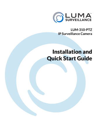
Figure 1: RS-485 LAN 1 or LAN 2 and earth system block diagram(3)LAN EarthChallenger panel(first device on LAN)Power Earth(6)D DTERM link on(1)RAS without earth terminal(2)D DTERM link off(1)RAS without earth terminal(5)(4)D DTERM link offExternal power supply(if needed)(3)(1)LAN EarthData gathering panel(last device on LAN)Power Earth(6)D DChallenger10 Installation and Quick Programming ManualTERM link on5
Figure 1 legendItemDescription1.RS-485 LAN cable. We recommend the use of 2-pair twisted shielded data cable such asBelden 8723 for optimal performance.2.Join data cable shields where cable extends past a device that doesn’t have a LAN earthconnection.3.In each segment of LAN cabling, connect one end only of the data cable shield to adevice’s LAN earth terminal.4.External 12 VDC power supply (if needed).5.Do not connect the from the external 12 VDC power supply to the of the LAN.6.Terminate the control panel and the most distant device, or the devices at the ends of thetwo longest LAN cable runs, as applicable.System configurationsA Challenger system’s RS-485 LANs (LAN 1 or LAN 2) may be configured in avariety of ways: Straight LAN, where the Challenger panel is at one end of a LAN cable run Star LAN, where multiple LAN cable runs are used in a branchedconfiguration Multi-building, where the LAN extends to more than one buildingLAN 1 is required and LAN 2 is optional. Each LAN must be independentlyconfigured and terminated.Straight LANIn a straight configuration (Figure 1 on page 5), the Challenger panel is at oneend of the LAN cable run and all other devices are connected to the LAN cable.The TERM links would be on for the Challenger panel and for the last device onthe LAN.Star LANIn a star configuration, the LAN has at least two branches (Figure 2 on page 7)optionally connected via a TS0844 Power Distribution Board (see “TS0844Power Distribution Board” on page 8). The TERM links would be on for the twodevices at the ends of the two longest cable runs.Note: A star LAN configuration may consist of a number of cable runs(branches). LAN termination should be set to ON only at the devices at the farends of the two longest branches. A star LAN that has multiple branches inexcess of 100 m may need to use LAN isolation devices such as TS0893 LANIsolation Interface modules to isolate the LAN segments that do not have LANtermination set to ON.6Challenger10 Installation and Quick Programming Manual
Figure 2: Star LAN configurationT OffDGPTS0844T OnT OnChallengerpanelT On (termination link fitted)T Off (termination link not fitted)T OffMulti-building or long-distance LAN cablingIf the RS-485 LAN extends to more than one building, each building must haveits own earth system. LAN isolation devices, such as TS0893 LAN IsolationInterface modules, are used to isolate the system LAN between buildings toprotect the system against differences in earth potential.Figure 3 below shows the use of two TS0893 modules to extend the RS-485 LANacross two electrical installations. Each TS0893 module has a pair of terminationlinks, used to terminate (if applicable) the LAN segment on each side of themodule’s isolation barrier.Figure 3: RS-485 LAN cabling between two buildingsBuilding A(3)Building BChallengerPanel(3)(5)(4)DGPDGP(1)T OnT OffT OnT OffTS0893TS0893T OnT OnT OnT On(2)T On (termination link fitted)T Off (termination link not fitted)Challenger10 Installation and Quick Programming Manual7
Figure 3 legendItemDescription1.LAN segment 1 extends from the Challenger panel to one side of the TS0893 LANIsolation Interface. Termination is ON at the panel and the panel’s side of the TS0893.Maximum cabling distance for segment 1 is 1500 metres.2.LAN segment 2 extends from the TS0893 in building A to the TS0893 in building B.Termination is ON at both TS0893 modules. Maximum cabling distance for segment 2 is1500 metres.3.Earth point on Challenger panel connected to building earth via plug pack earth wire(green).4.Earth point on remote device connected to building earth via plug pack earth wire (green),or earth wire from local power supply.5.Plastic-body LAN device. Join data cable shields where cable extends past a device thatdoesn’t have a LAN earth connection.Using LAN devices to facilitate cablingVarious LAN devices may be used to provide electrical isolation and to reducecabling costs. LAN isolation devices can also be used to extend the distance ofLAN cabling beyond what can be achieved by a single cable run of 1.5 km. LANdevices include the following: TS0844 Power Distribution Board. The TS0844 module can be used ineither data or power mode, as set by a pair of onboard links. The TS0844module expands the number of physical connections that can be made to thepanel’s power or data output terminals. In data mode, each TS0844 module provides five sets of LAN outconnections and five sets of and – auxiliary power output terminals. In power mode, each TS0844 module provides 10 sets of and – auxiliarypower output terminals.A TS0844 module is shown in Figure 2 on page 7. TS0893 LAN Isolation Interface. Provides an optical isolation barrierbetween components on a Challenger (or Intelligent Access Controller) LAN.The TS0893 can be also used as a LAN repeater, with up to three stagescascaded together to increase the maximum LAN cabling run from 1.5 km to6 km. TS0893 modules are shown in Figure 3 on page 7. TS0896 RS-485 to Fibre Optic Interface. A pair of TS0896 modules, withsuitable optical fibre cable, may be used to extend the LAN to remotebuildings or locations within a building (for example where unused opticalfibre cable already exists). TS0098 Challenger IP LAN Adaptor: Multiple IP LAN Adaptor modulesenable Challenger LAN data to be carried over an IP network and to beconverted back to RS-485 communications for connection to LAN devices.Refer to the Interlogix Web site at www.interlogix.com.au for details and imagesof LAN devices.8Challenger10 Installation and Quick Programming Manual
Installing the control panelSee Figure 4 below for overall details of a TS1016 Challenger panel installed in aTS0307 Universal Enclosure.Figure 4: Challenger panel board mounted in enclosure(3)(1)(1)(2)(2)TS1016board(2)(2)Space for 12 V 7 Ah battery(not included)(1)(1)Figure 4 legendItemDescription1.Enclosure mounting points2.Board mounting points3.Location of tamper switchInstallation guidelinesChallenger panels are designed, assembled and tested to meet the requirementsrelated to safety, emission and immunity with respect to environmental electricaland electromagnetic interference, as of current relevant standards.In addition to the general installation guidelines, installers must adhere to anycountry dependent requirements of local applicable standards. Only a qualifiedelectrician or other suitably trained and qualified person should attempt to wirethis system to mains power (if applicable) or to the public telephone network.Challenger10 Installation and Quick Programming Manual9
The general installation guidelines are as follows: Mount the unit using screws or bolts through the four mounting holes in thebase. Ensure that the unit is mounted on a flat, solid, vertical surface so thatthe base will not flex or warp when the mounting screws or bolts aretightened. Allow 50 mm clearance between the equipment enclosures mounted side byside, and 25 mm between the enclosure and any side wall or ceiling. The Challenger panel is powered and earthed via a 16 Volt AC plug pack(supplied). A power outlet (GPO) must be in proximity to the panel. Onlyqualified Electricians should provide a GPO. The Challenger panel has an onboard dialler. Telephone connections must bein proximity to the panel. Only ACMA Cablers should provide telephonecabling. If the upper and/or lower ca
Challenger is a scalable intrusion detection and access control system. Challenger panels use one, and optionally a second, RS-485 data bus (LAN) to provide continuous polling of remote arming stations (RAS) and data gathering panels (DGP). These devices extend the system


![Fluent Python : [clear, concise, and effective programming]](/img/1/799981060.jpg)