Transcription
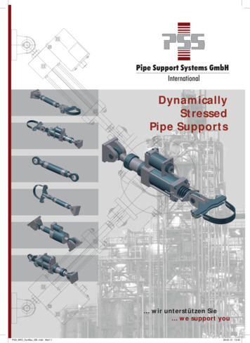
nINTERNATIONALBD-144, BD-154 SeriesDIESEL ENGINESandBC-144SeriesPETROL ENGINESSM-12AINTERNATIONAL HARVESTER COMPANYof GREAT BRITAIN LIMITEDP.O.BOX25 259 CITY ROAD LONDON ECIP 1ADKBB/4/78 MeC
i .'
GENERALSM-11ASERVICE MANUALMANIFOLDS.CYliNDER HEADAND VALVESCONNECTING RODS.PISTONS ANDCYLINDER SLEEVESINTERNATIONALLUBRICATIONSYSTEMBC-144 BD-144 & BD-154SERIES ENGINESThe black tabs shown on the right-hand side of this pageline up with the corresponding tabs on the index pagesof the respective groups.NOTERefer to the SUPPLEMENT AND CHANGE INDEX for a listof supplements.and to the end of the appropriategroup forthe latest instructions. before carrying out work on this equipment.COOLINGSYSTEMTIMING GEAR TRAIN.FRONT COVERAND CAMSHAFTCRANKSHAFT MAIN BEARINGSAND FLYWHEELGOVERNORBC -144 ENGINECARBURETTORBe -144 ENGINEINTERNATIONAL HARVESTER COMPANYOF GREAT BRITAIN LIMITEDPO BOX 25, 259 CITY ROAD, LONDON EC1P lADLPG ATTACHMENTBC-144 ENGINE
r---------
INTERNATIONAL8C-144, 80-144 & 80-164SERIES ENGINESGROUPGENERAL1
1- 11. INTRODUCTION1a. GENERALThe instructionscontainedin thisservicem an u a l are for the informationand guidanceof servicemenwho areresponsiblefor overhaulingand ,and BC-144petrolengines., b, SERVICETOOLSInternationalenginesare designedso that few specialtoolsare required.However.wheneverthe use of inexpensive specialserviceequipmentwillfacilitatework.such equipmentismentionedin this manual.Wherethis equipmentcan easilybe madein the workshop.dimensionaldrawings have been provided.1c. SERVICEPARTSI.H. enginesdeservegenuineI. H.serviceparts.The best materialobtainableand experiencegainedthroughmany yearsof constructionand farm equipmentmanufacturingenablethe InternationalHarvestercompanyto producequalitythat willnot be found in imitationor "justasgood"repairparts.No servicemancan affordto guaranteea repairjobthat has not been servicedwith genuine I.H. parts.For the correctservicepartsto be used alwaysreferto the Parts Catalogue.The looseleat cataloguesare accurateand arebroughtup to date continuallybyissuingrevisions.td. SERIAL·NUMBERSThe engineserialnumberis stampedon a pad on the R. H. side of thecrankcase.u1f. ELECTRICALFull detailsof servlclngand adjusting the electricalequipmentwill befound in the "ELECTRICALEQUIPMENTSERVICE MANUAL SM-14",1g. ADJUSTMENTSWhereadjustmentsare necessarythe group will containthe relevantinformation.Referenceto that section beforecommencingto dismantlethe unit may preventunnecessarywork beingcarriedout.1h. ILLUSTRATIONSFour typesof illustrationwill be foundin this-manualtheseare explainedby theexamples:referencesandfollowing(a) (1-4)This refersto the itemmarkedby indicatornumber1 inFIGURE 4 of the GROUP in whichthere ferenceappears.(b) (1 & 2-4) This refersto theitemsmarkedby indicatornumbersi and 2 in FIGURE 4 of the GROUPin whichthe referenceappears.(c) (1-4& 2-6)This refersto itemsmarkedby indicatornumber1 inFIGURE 4 and indicatornumber2 inFIGURE 6 of the GROUP in whichthereferenceappears.(d) (1-4GROUP 5) This is usedwhen referenceis made to an illusttrationin anotherGROUP,A GROUPnumbermay be used in conjunctionwith (a).(b).or(c)toshowtheindicatornumber.FIGURE numberand GROUP in whichthe illustrationappears,1i. INSPECTION AND REPAIR1e. DIESEL FUEL INJECTION EQUIPMENTIf detailedinformationon the fuelinjectionequipmentand fuel liftpump is desired.referto the"FUELIIINJECTIONSERVICE MANUAL SM-ll.The f o Ll o w Lng notesshouldbe usedas a generalg u i d e to inspectionandrepair.Wherea specialprocedureisnecessaryfor a componentor assembly.full detailsw ill be found in therelevantsectionof the group,
2 ·1(a)(h)BEARINGSInspectfor evidenceof placeif necessary.Soak in oil.wrap or coveruntilreadyfor assembly.(b)PINSAND .scoringandwith matingpartsforAND SEALSAlwaysuse newduringassembly.ful not to damageduringinstallation.sealswith greaseever a seal has tosplinesor threads.(d)GEARSgasketsand sealsBe extremelycarethe seal or ga-sketpack lip typeand use sleeveswherebe passedoverAND SPLINESCheckall weldedassembliesforcracks.tWistingand misalignment.Informationconcerningthe use ofspecialweldingrods or weldingprocedureis detailed.whererelevant.in the appropriatesectionof thegroup.(f) CASTINGS(g)castingsCheckfor damagedor missingfittingsand replace.Checkthatgreaseand oil galleriesare clear.1j. LUBRICATIONWhencoat alllubricantmanual.lubricants e iz in g ,when theassemblingany part.alwayswearingsurfaceswith thespecifiedin the operator'sUse sufficientquantitiesofto preventany dangerofscoringor excessivewearassemblyis first operated.FAILURE TO PROVIDE "STARTINGLUBRICATION"MAY RESULT INSERIOUS DAMAGE.The followingtablegivesconversion factorsfor use in convertingthe Britishspecificationsto theirmetricequivalents:To convertfrom:WELDSChecktortion.FITTINGS1k. METRICCONVERSIONSCheckfor cracks.pitting.burrs.brokenor missingteeth.Checkforexcessivewear with matingparts.Removeburrs c a r e fu l l y DO NOTinterferewith toothor splineprofile.REPLACE all partswhichshow damageor excessivewear.(e)LUBRICATIONforFUEL. OIL ANDAND HOSEScracksCOOLANTanddis-PIPESCheckunionsfor leaks.strippedthreadsor otherfaults.Checkpipesfor cracksor chafing.hoses forchafing.twisting.perishingor nceskg.02835lb ftmetre - kg.1383lb inmetre - kg.0115Ib/in2kg/ cm2.07031Imp gaUslitres4.5454Imp pintslitres.5682mileskm1.6T70-12I
3-'2. BOLT IDENTIFI CATION CHARTIHTYPEBSS2RMAN UF ACTURERSR45-55NEWALLHIT ENSILEBEES45 R 55MARKIN GSSPNRNEWTONRSPARTSRTWLR"R"4TT55-65BEES55 T· 65NEWALLOYTor 5 V 75NEW ALLOYSPNVNEWTONVSPARTSVTWLV"V"T70-1283. STANDARD TORQUEDATA FOR NUTS AND BOLTSWhereno specialtorqueused on all nuts and boltsoil or challisgrease.datais specified.providingthat thethe followingtorquethreadsare enr e - u s t n gnuts andbolt sins e r vic eiu lethemIn i mumtor quefig u r (.
4-14. SPECIFICATIONSThewornnot apartsearlyfollowingcomponentscomponentto servicedate.specificationsare listedin GROUP order.Duringthe overhaulofpersonalinitiativemust be exercisedto determinewhetheroris suitablefor re-use.It is obviouslyuneconomicalto returnwornwith an expectationof life whichmay involvelabourcostsat anBC-144 SeriesBO-144 SeriesBO-154 Series1. GENERALNumber of cylinders( in)Bore( in)Stroke(in3 )DisplacementCompression ratioCompression pressure lb/ in2at 200 rev/minat 300 rev/minFiring orderENGINESPEED (rev/min)Full load. governed43-3/841446.3: ne (LPG)2200143-1/2415423 :1445/470510/5351-3-4-2BD-144Mechanical Governor1750 -: 10BD-154DPA Injection Pump2000BD-144Pneumatic Governor1800BD-154DDPA Injection Pump2000BD-144APneumatic Governor1900BD-144Pneumatic Governor(for B-55 Baler)1525 -: 10BD-144Mechanical Governor( for Canadian Engine)2000 10BD-144DPA Injection Pump1775BD-144ADPA Injection Pump1900BD-1448DPA Injection Pump1525BD-l44C & BD-l44F2000BD-l44 (DPA)6000 ft Derated1775BD-l44A (DPA)6000 ft Derated1900BD-144C &BD-144F(DPA)6000 ft Derated2000BD-154HDPA Injection Pump2200BD-154 (DPA)6000 ft Derated2000BD-154H (DPA)6000 ft Derated2200
6- 1BC-144 SeriesENGINESPEED - ContinuedHigh idleLow idleBC-1442200 -: 25BC-144A2075 25BC-144H2400: 25BC-l44HPropane (LPG)2400 2580-144 Series80-154 SeriesBD-144Mechanical Governor1925:- 40BD-144Pneumatic Governor1860 to 1900BD-144APneumatic Governor2000 Max.BD-144Pneumatic Govemor( for B-55 Baler)1700 Max.BD-V14Mechanical Governor( for Canadian Engine)2200 t 25BD-144DPA Injection Pump19'25 :: 25BD-1441\DPA Injection Pump2075 t 53D-144BDPA Injection Pump1600! 25BD-144C &. BD-144FDPA Injection Pump2200 t 25BD-144 (DPA)6000 ft Derated1925 ! 25BD 144A (DPA)6000 ft Derated?'U'/5 25flD-144C R -BD-144F(DPA)nlH)l1 tr Derate"- VIJ 25BD-154DPA Injection Pump2200:25BD-154DDPA Injection Pump2200 ! 25BD-154HDPA Injection Pump2380 t 25BD-154 (DPA)6000 ft Derated2200! 253D-154H (DPA)6000 ft Derated2380 -: 25BD-144Mechanical Governor475 to 025All Pneumatic Governors540t0600Mechanical Governor( for Canadian Engine)500 to 550All Versions With DPAPumps520 to 580All Versions,H1 V,:rSlOns- 2505(11)FUELPetrol - 82 octaneLPG - High Purity Propane(C3 H8)Diesel520 to 580NOTE: When speedamplifier attachmentis fitted to 434 tractors low idle setting is750 to 800.Diesel
6-1BC-144SeriesBD-144SeriesBD-154Series2. MANIFOLDS.CYLINDERHEAD8t VALVESINLETVALVES()Stem diameterPort diameterHead diameterClearance in guideValve face angleValve seat angleTappet clearance( in)( in)( in)( in)( in)0.341/ O. 3421. 2521. 407/1. 4170.002/0.00444 30' to 45 45 0.020 Hot & Cold0.341/ O. 3421.3101. 465/1. 4750.002/ 0.00444 30' to 45 45 0.020 Hot & Cold0.341/ 0.3421. 3101. 465/1. 4750.002/ 0.004440 3 O' to 4504500.020 Hot & Cold0.341/ O. 342BD-l44. 144A & 144B1.105BD-144C & BD-144F1.0161. 171/1. 1810.002/0.00444 30' to 45045 0.020 Hot & Cold0.341/ 0.3421.016EXHAUSTVALVESStem diameterPort diameter( in)( in)0.341/ O. 342Valve seat insert1. 090Head diameterClearance in guideValve face angleValve seat angleTappet clearance( in)1. 245/1. 255O. 002/ 0.00444 30' to 45 45 0.020 Hot & Cold( in)( in)1. 171/1. 181O. 002/ O. 00444 30 t045 4500.020 Hot &. ColdVALVEGUIDESLength- inletLength-exhaustInside diameterSet height of guidemeasured fromHeight-inletHeight -exha ust( in)( in)( in)( in)( in)2.4692.62.50.344/ O. 345Spring recess0.8280.9843.2503.0000.344/ O. 345Cylinder head top deckO. 940 0.030O. 940 0.030VALVESPRINGSTest LengthTest loadMin. length in useMax. length in useFree length( in)(lb)( in)( in)( in)3.2503.0000.344/ O. 345Cylinder head top deckO. 940 0.030O. 940 51. 8702,5501.34675.4 3.51.3461.7002.0851.67242.5 -: . 21. 5621. 9222. 531 0.0470.748/ 0.7490.002/ 0.0040.751/ 0.7520.7495/ 0.75100.748/ 0.7490.002/ 0.0040.751/ O. 7520.7495/0.75100.748/ O. 7490.002/ 0.0040.751/ O. 7520.7495/0.75100.560/0.561O. OOOS/ O. 0030.560/ 0.561O. OOOS/ O. 0030.560/ 0.5610.0005/0.003VALVELEVERS,SHAFT ANDBRACKETSShaft diameterRunning clearanceBushing I. D.Brackets bore( in)( in)( in)( in)VALVETAPPETSDiameterRunning clearance( in)( in)
7-1BC-144 Series80-144 Series80-154 10.510/10.540200 before TDC400 after BDC400 before BDC100 after TDC200 before TDC400 after BDC400 before BDC100 after TDC200 Before TDC40 after BDC40 before BDC100 after TDC75/8075/8075/80ft)20/3020/30ft)30/3530/35VALVE PUSH RODSDiameterLength( in)( in)VALVE TIMINGInlet opensInlet closesExhaust opensExhaust closesTORQUE LOADINGSCylinder head bolts (lbNozzle body stud orbolt to cylinder head (IbNozzle body nut to(lbstudTappet adjusting screw(lbnutValve housing 1. 8755/1. 87600.001/ O.00290.003/0.0101.1028/1.10311. 8755/1. 8760O.001/ O.00290.003/0.0101.1028/1.10311. 8755/1. 8760O.001/ O.00290.003/0.0101.1028/1.10311.1021/1.10231. 1071/1. 10731.1021/1.10231.1071/1. 10731.1021/1.10241.1071/1.1074O.OOS/0.020O.00025 Loose toO.00015 tight0.0005/0.00102.898/2.9020.012/0.0200.00025 Loose toO.00015 tighto. OOOS/0.00102.898/2.902O.012/ O.021O.0003 Loose toO.0005 tightO.0005/ 1/0.00390.0039/ 0.004750.0031/ 0.00390.0039/0.004753. CONNECTINGRODS.PISTONSAND CYLINDERSLEEVESCONNECTING RODSCrankshaft bearingdiameterRunning clearanceSide clearancePiston pin bush ID( in)( in)( in)( in)PISTON PINSDiameter( in)StandardOversize - marked 5Clearance between endof pin and circlip( in)Clearance in piston ( in)Clearance in con rod (in)( in)LengthPISTONSSkirt clearance at bottom 900 from pinhole ( in)GradedIndividual replacementsNumber of rings
8- 1BC-144 SeriesBO-144 / 0.190O. 0963/ O. 09690.0967/ 0.09730.0959/ O. 09650.1877/0.1883BO-154 SeriesPISTONS - ContinuedWidth of ring grooves (in)Top compressionSecond compressionThird compressionOil controlRing clearance in( in)groovesTop compressionSecond compressionThird compressionOil controlTopBottomOil controlTopBottomf)O. 0018/0. 0033O. 0018/0. 0033O. 0018/ 0.0033O. 0025/0. 0040Not applicable0.0028/0.0039O. 0032/ O. 0043O. 0024/0: 0035BD-144 & BD-l44BO. 0012/ O. 00230.0012/ 0.0023BD-l44A. 144F & 144CNot applicable0.0012/ O. 0.18830.0035/0.0055O. 0035/0. INGS- CompressionNumber of rings per pistonTypeTopSecondThird(in)Width of all ringsRing gap. All rings ( in)ChromeTaper faceTaper face0.0930/0.09350.012/ O. 018333Chrome internally steppedPlainPlainO. 0930/0. 09350.012/0.018ChromeInternally steppedInternally stepped0.0927/0.09370.015/0.019PISTON RINGS - Oil controlNumber of rings per pistonTypeTopBottomTypeTopBottom( in)Ring gapTopBottom( in)Ring gapTopBottomf)1SlottedNot applicable0.012/ O. 018Not applicable2BD-144 & BD-l44BSlottedSlottedBD-144A. 144F & 144CMulti -pieceSlottedBD-144 & BD-144B0.012/0.0180.012/0 018BD-144A; 144F & 144Co 015/ 0.0450.012/ SLEEVESWall thicknessSleeve O. D.( in)(in)Flange stand outFlange widthMax. taperMax. ovality( in)( in)( in)( in)0.2134/0.22353.6865/3.688(packing ring)0.001/ O. 0050.227/ 0.229O. 00050.00080.2134/ 0.22353.6865/3.688( packing 61253 6865/3.688(packing ring)O. 001/ O. 0050.227/ ecting rod bolts (lb ft)Issue2 SM12A5/69
10· 1BC-144 SeriesBO-144 SeriesBO-154 Series6. TIMINGGEARTRAIN.FRONTCOVERANDCAMSHA
parts to service with an expectation of life which may involve labour costs at an early date. BC-144Series BO-144Series BO-154Series 1. GENERAL Number ofcylinders 4 4 4 Bore (in) 3-3/8 3-3/8 3-1/2 Stroke (in) 4 4 4 Displacement (in3 ) 144 144 154 Compression ratio 6.3: 1 21.1: 1 23 :1 Compression pressure lb/ in2 at 200 rev/min 80/105 330/355 445/470 at 300 rev/min 90/115 350/375 510/535 .
