Transcription
Technical white paperHPE Synergy installation andrecommended practices guideVMware vSAN ReadyNode on HPE SynergyContentsAbout this document .2Introduction . 2Audience.2Assumptions .2Design scenario .2Blueprint for vSAN on HPE Synergy .4Configuration process . 4Step 1: vSAN network creation in HPE OneView .4Step 2: HPE OneView server profile templates and vSAN node creation . 5Step 3: Installation and setup of ESXi . 6Step 4: vSAN Health remediation. 13Summary . 17Resources . 18
Technical white paperPage 2About this documentIntroductionIT organizations are looking for robust infrastructure, which is flexible, cost-efficient, scalable, and provides a stable platform for mixed workloadswithout compromising on performance and the IT organization’s ability to meet the required service-level agreements to its users. HPE Synergyis architected from the ground up for Composable Infrastructure. The performance, flexibility, and manageability that HPE Synergy provides helpbusinesses provision efficiently, scale on-premises cloud infrastructure resources quickly, and reduce costs associated with stranded resources.Composable Infrastructure is the next-generation platform customers are adopting and through partnership, Hewlett Packard Enterprise andVMware have collaborated to certify HPE Synergy for VMware vSAN. This disaggregated architecture of compute, storage, and fabric allows theinfrastructure administrator to avoid fixed ratios found in traditional infrastructure. It also provides a single unified API to assemble theinfrastructure to meet business needs. VMware has certified vSAN ReadyNodes for vSAN 6.6/VMware ESXi 6.5 U1 for all-flash configurationsand VMware ESXi 6.0 U3 for hybrid deployments on HPE Synergy.AudienceThis document is intended to aid infrastructure and virtualization administrators in configuring their HPE Synergy infrastructure for VMwarevSAN 6.6.AssumptionsIt is assumed that the infrastructure for the use case complies with VMware Hardware Compatibility List (HCL).Design scenarioThe solution discussed in this white paper assumes a deployment of at least: One HPE Synergy frame including, at a minimum:– HPE Virtual Connect SE 40Gb F8 Module for Synergy– Three HPE Synergy 480 Gen9 nodes with HCL compatible components (see “HCL AF-6 example” section)– HPE Synergy D3940 Storage Module with SAS expanders– Redundant HPE Synergy Composer modules running HPE OneView 3.1– Highly available HPE Synergy Frame Link Modules, power supplies, and fans– VMware vCenter 6.6 appliance (VMware vCenter Server Appliance [VCSA]) or stand-alone vCenter installation using Microsoft Windows Server and SQL database Additionally, administrators may wish to obtain:– ESXi Image for HPE ProLiant– HPE OneView for VMware vCenter plug-in appliance– HPE Synergy Configuration and Compatibility Guide– kb.vmware.com/selfservice/microsites/search.do?cmd displayKC&docType kc&externalId 2151225
Technical white paperPage 3HCL AF-6 exampleFigure 1. Example of HPE Synergy ReadyNodeQ. Can the administrator change options in the build list?A. Yes, but only certain options. Visit ot-change-vsan-readynode for changes such asboot devices, group configurations, and others. Disk groups must be HCL compatible for minimum—only drives in higher performance SKUs willstill be allowed.Q. Can the administrator use HPE Synergy Image Streamer?A. Yes, according to VMware, modifying the boot device is an allowable configuration change, and this will be covered as part of the document.The administrator must be using the 3-frame logical enclosure to support this use case. For more information on HPE Synergy Image Streamer,visit tml.Q. Does this document represent the only way to deploy vSAN on HPE Synergy?A. No. This document is not intended to be the last word on vSAN deployments on HPE Synergy. Just as the build list for a ReadyNode can bemodified, so can the deployment options illustrated in this guide be modified. For example, this guide leverages HPE FlexNic technology as wellthe VMware vSphere Distributed Switch . The vSAN administrator may leverage different networking schemes provided it does not violate anyvSAN constraints.
Technical white paperPage 4Blueprint for vSAN on HPE SynergyThe remainder of this document assumes HPE Synergy infrastructure has undergone initial discovery of HPE Synergy frames and installedcomponents. A firmware baseline compliant with VMware HCL should be applied to the logical enclosure to meet compatibility requirements.The basic process for configuring vSAN is as follows:NoteThe steps listed here are generic. If you are unsure of how to perform each step, use the HPE OneView Deployment and Management Guide(DMG) for detailed steps on each portion of the configuration. The page numbers for each step will be listed next to the step:1. Initial configuration of the HPE Synergy environment (DMG: page 25).a. Define IP ranges for management and HPE Synergy Composer powered by HPE OneViewb. Service Pack for ProLiant uploaded to HPE Composer powered by HPE OneView2. Network creation and configuration (bandwidth requested, max. 20 Gb) (DMG: page 31).a. Management (0.1 Gb–1 Gb)b. vSAN (10 Gb)c. VMware vSphere vMotion (4 Gb–8 Gb)d. Production guest networks (1 Gb–5 Gb)3. A logical enclosure created within HPE OneView consisting of all HPE Synergy frames interconnected by the same fabric resources (DMG:page 45).a. Logical interconnect groupsI. 40 Gb module pairII. SAS module pairb. Enclosure groups created with appropriate networks and uplinks included in logical interconnect groupc. Firmware baseline SPP addedd. Update logical enclosure firmwaree. HPE Synergy Image Streamer (optional)4. VMware vCenter 6.5 sets up externally to the logical enclosure with connectivity to the management and production networks.Configuration processStep 1: vSAN network creation in HPE OneViewDepending on the needs of the local environment for VMware vSAN, the private vSAN network can be used internally within the logical enclosurethat provides up to 240 Gb east-west traffic. It can also be externally exposed to top-of-rack (ToR) switches to extend the cluster beyond asingle logical enclosure. Utilizing an internal-only vSAN network eliminates the need for data center-wide Jumbo Frame enablement on all ToRand core switches as Jumbo Frames are natively enabled with the HPE Synergy fabric.If the environment requires that vSAN cluster nodes participate with nodes beyond an HPE Synergy logical enclosure, then it is necessary todefine the vSAN network on an HPE Synergy logical interconnect group uplink set to enable vSAN traffic to participate in the data centernetwork. Scaling beyond a single logical enclosure can also be accomplished using VMware Stretched Clusters without plumbing the vSANnetwork externally.
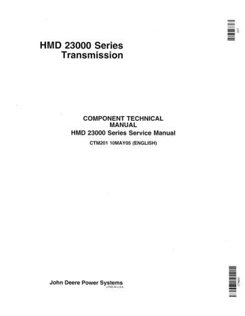
Technical white paperPage 5Figure 2. Configuring the vSAN network in HPE OneViewThe recommended vSAN bandwidth is always 10 Gb for all-flash configurations and from 1 Gb to 10 Gb for hybrid.NoteVLAN tags are not specific to vSAN and can be adjusted by the administrator.Step 2: HPE OneView server profile templates and vSAN node creationHPE OneView provides infrastructure architects with a software-defined methodology to define a template that specifies all necessaryparameters for the compute module. It includes firmware baseline, network connections to deployment, management and production networks,array controller settings, configuration of local and HPE Synergy D3940 enclosures and drives, and BIOS settings.HPE OneView architects may choose to define templates to use HPE Synergy Image Streamer or PXE-based deployment services or may chooseto use manual methods to install VMware ESXi on the front-facing drives in RAID configuration.The following steps incorporate best practices in accordance with typical ESXi deployments and can be modified to fit the environment’s needs(other than firmware baseline).In HPE Synergy Image Streamer or PXE-based OS deployments, it is required to map the first port of each LOM (3:1a and 3:2a) to thedeployment services. If manual methods are used, ports 3:1a and 3:2a are available for management or other networks.1. Profile naming and basicsa. Naming and description for vSAN node consistency (that is, vsan node no I3S)b. Make sure template is applied to correct hardware type for HPE Synergy 480 nodes2. Firmware baseline attached to correct SPP with HCL approved firmware3. Network connections (See procedure Blueprint for vSAN on HPE Synergy, step # 2 for bandwidth recommendation)a. 3:1a and 3:2a Open/administrator useb. 3:1b and 3:2b Management and/or vMotionc. 3:1c and 3:2c VM Guests and/or vMotion (depending on 3:1b)
Technical white paperPage 6d. 3:1d and 3:2d vSAN Storage NetworkNoteThis network configuration and NIC assignment is only one recommendation of many valid configurations and should not be considered thepreferred configuration or layout. Other valid configurations could include a redundantly configured Network Set or Tunnel network with allVLANs trunked to each compute node. If leveraging a 2-NIC configuration with a Network Set or Tunnel network, then the VMwareDistributed Switch and Network I/O Control (NIOC) is strongly recommended. Networks for replication, backup, or disaster recovery shouldalso be considered as part of the solution.4. Storagea. Internal drives RAID 1 (if not using HPE Synergy Image Streamer)I. Set to BootII. Initialize at startupb. HPE Synergy D3940 drives HBA mode (use administrator predetermined group for cache-to-data ratio; ReadyNode example using1 to 3)I. SSD cache drives (one per group)II. SSDs/HDDs (nodes per group x cache drive amount)c. SAN storage Not necessary, leave unconfigured5. Boot settingsa. Boot modes UEFI Optimizedb. PXE Boot Autoc. Manage Boot Order Hard Disk (unless using PXE or HPE Image Streamer)6. Optional: BIOS settingsa. Select Manage BIOSb. Set Power Profile to Max. Performance (optional)c. Set Power Regulator to Static High Performance Mode (optional)Now that the server profile template (SPT) has been created, the next step is to apply profiles to each of your available HPE Synergy 480 nodesavailable for vSAN.1. Select SPT created earlier and click the Actions tab on right and select Create Server Profile2. Pick the applicable HPE Synergy 480 node, apply the template, and click OKStep 3: Installation and setup of ESXiThere are two ways to install ESXi that are both valid for HCL compatibility—HPE Synergy Image Streamer or standard ISO installation to localRAID 1 drives. In this document, we will focus on the local media installation procedure.NoteThere is a configuration change that must be performed on the ESXi node via Shell commands that allows true active/passive SAS drive failoverin ESXi.1. After all profiles are applied, record the HPE OneView assigned MAC addresses to the networks. These will be necessary to keep congruencewith the vmnic (that is, vmnic0 Mgmt1) when assigning physical NICs to vDS uplinks in later steps.2. Boot the nodes and install ESXi through HPE iLO mount of ISO media.3. After installation is completed, select the management networks in setup and configure applicable IP, DNS, Gateway, and FQDN.
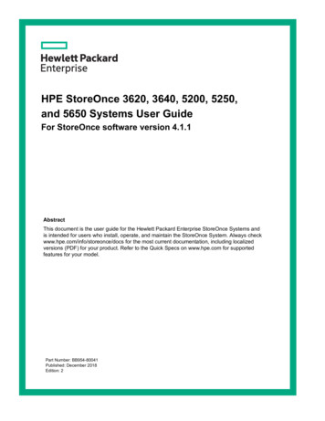
Technical white paper4. Enable SSH and ESXi Shell.5. Connect to each host via SSH or local Shell and run this set of commands in the following order:a. esxcli storage nmp satp rule add -D nhpsa -s VMW SATP DEFAULT APb. esxcli storage core claiming unclaim -t driver -D nhpsac. esxcli storage core claimrule loadd. esxcli storage core claimrule runFigure 3. Modifying VMware vSphere claim rulesNoteThe unable to unclaim path warning is to be expected. This is pointing to the local boot disk.Page 7
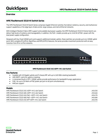
Technical white paperPage 86. The commands allow ESXi to see both paths to the SAS drives and allow true active/passive failover in case of a SAS connection module orI/O adapter being offline. The following screenshot should be the result shown on each SAS disk.Figure 4. Storage Devices Path detail7. If not already created, in vCenter create a new data center as well as a new cluster (vSAN Cluster 1); put your required settings for VMwarevSphere High Availability, VMware vSphere Distributed Resource Scheduler , and others. Add the ESXi hosts to this cluster.Figure 5. vSAN Cluster settings
Technical white paperPage 98. In vCenter, create a virtual distributed switch (vDS). Since HPE Synergy profile is configured for six HPE FlexNics, configure the vDS for sixuplinks. Uncheck Create a default port group. Right-click and choose Settings, and then Edit Settings. On the General Tab, choose EditUplink Names and edit the uplink names to correspond to HPE FlexNics set in the profile. This will help eliminate confusion when hosts areadded to the vSwitch.Figure 6. Edit the Uplink Names9. If Jumbo Frames will be used, select Advanced, then set MTU at 9000, and optionally change discovery protocol to Link Layer DiscoveryProtocol. Jumbo Frames are not required for vSAN, but performance gains may be realized if they are leveraged.Figure 7. vDS Advanced settings10. Create a Distributed Port Group named Management and accept all defaults.11. Create a Distributed Port Group vSAN Network and accept all defaults.12. Continue creating additional Port Groups, configuring VLAN IDs as appropriate.
Technical white paperPage 1013. Note: HPE Synergy 480 compute nodes do not have LACP available but rather standard LAG configuration (side A/side B). In the VMwaredocument, VMware vSAN Network Design, there are multiple examples of LAG configurations that can be used by either rackmount orblade/modular servers. For this best practices document, the standard Basic NIC Teaming example is used, as the nodes are LAG but theHPE Virtual Connect modules are active/active.a. Some performance gains may be achieved by adjusting the teaming and load balancing algorithms to Load Based Teaming. These areconfigured on a per-port-group basis.14. Right-click the vDS and choose Add and Manage Hosts. Choose the Add Host option and select the Template Mode option. Add each host.Choose the Manage physical network adapters and Manage VMkernel network adapters. For Manage physical network adapters, assigneach of the vmnics to the corresponding appropriate vDS uplink name. Choose Apply to all to apply the physical network adapterassignments to all other hosts.Figure 8. Add and Manage Hosts—Manage Physical Network Adapters
Technical white paperPage 1115. Migrate the default vmk0 adapter to the vDS.Figure 9. Add and Manage Hosts—Manage VMkernel Network Adapters16. Choose New Adapter and create a new VMkernel adapter for vSAN Network. (optionally, continue creating additional VMkernel adapters,such as those to be used for other storage topologies, vMotion, and more).17. After choosing Finish in this wizard, all hosts and host adapters will be migrated to the VMware Distributed Switch. Following completion ofthis wizard, additional Port Groups can be created, vMotion settings configured, and so on.
Technical white paperPage 1218. Next, configure each Port Group to leverage only those uplinks that are carrying that Port Group’s traffic (for example, the vSAN network PortGroup should be bound only to the vSAN uplinks).Figure 10. Assigning Uplinks19. Go to the vSAN Cluster tab Configure and select the vSAN tab on the left menu. Check General submenu and make sure vSAN is turned ONand all disks are using the correct On-Disk Format Version. If not, proceed to update these. Next, click the Disk Management submenu and ifthe option to automatically import drives is set to OFF, then the administrator will need to add each host’s disk group manually. This can bedone by allowing vSAN to claim the correct cache and capacity tier drives. Once this is completed, VMware will import the drives and placethem in the disk groups to be available for use within the cluster.a. Note: Should a disk be pr
VMware has certified vSAN ReadyNodes for vSAN 6.6/VMware ESXi 6. 5 U1 for all-flash configurations and VMware ESXi 6.0 U3 for hybrid deployments on HPE Synergy. Audience . This document is intended to aid infrastructure and virtualization administrators in configuring their HPE Synergy infrastr