Transcription
Getting startedFLIR A400 series,FLIR A700 series
Table of contents1 List of contents . . . . . . . . . . . . . . . . . . . . . . . . . . . . . . . . . . . . . . . . . . . . . . . . . . . . . . . . . . . . . . . . 12 Illustrations . . . . . . . . . . . . . . . . . . . . . . . . . . . . . . . . . . . . . . . . . . . . . . . . . . . . . . . . . . . . . . . . . . . . 23 EN-US English . . . . . . . . . . . . . . . . . . . . . . . . . . . . . . . . . . . . . . . . . . . . . . . . . . . . . . . . . . . . . . . . . 54 DE-DE Deutsch . . . . . . . . . . . . . . . . . . . . . . . . . . . . . . . . . . . . . . . . . . . . . . . . . . . . . . . . . . . . . . . . 95 ES-ES Español . . . . . . . . . . . . . . . . . . . . . . . . . . . . . . . . . . . . . . . . . . . . . . . . . . . . . . . . . . . . . . . .146 FR-FR Français . . . . . . . . . . . . . . . . . . . . . . . . . . . . . . . . . . . . . . . . . . . . . . . . . . . . . . . . . . . . . . .197 IT-IT Italiano . . . . . . . . . . . . . . . . . . . . . . . . . . . . . . . . . . . . . . . . . . . . . . . . . . . . . . . . . . . . . . . . . . .248 JA-JP 日本語. . . . . . . . . . . . . . . . . . . . . . . . . . . . . . . . . . . . . . . . . . . . . . . . . . . . . . . . . . . . . . . . . . .299 KO-KR 한국어. . . . . . . . . . . . . . . . . . . . . . . . . . . . . . . . . . . . . . . . . . . . . . . . . . . . . . . . . . . . . . . . . .3410 PT-PT Português . . . . . . . . . . . . . . . . . . . . . . . . . . . . . . . . . . . . . . . . . . . . . . . . . . . . . . . . . . . . . .3811 ZH-CN 简体中文 . . . . . . . . . . . . . . . . . . . . . . . . . . . . . . . . . . . . . . . . . . . . . . . . . . . . . . . . . . . . . . .4312 ZH-TW 繁體中文 . . . . . . . . . . . . . . . . . . . . . . . . . . . . . . . . . . . . . . . . . . . . . . . . . . . . . . . . . . . . . . .47#T810482; r. AA/64581/64581; muliii
1 List of contents Infrared camera.Depending on the model, the camera is delivered: as a bare camera (FLIR A400/A700)mounted in an environmental housing (FLIR A400f/A700f), ormounted in a pan/tilt unit (FLIR A400pt/A700pt).Ethernet cable M12 to RJ45F (0.3 m), P/N T911869ACC (FLIR A400/A700).Installation kit (FLIR A400f/A700f and FLIR A400pt/A700pt).Printed documentation including the username and password for log in to theweb interface of the camera.Note FLIR Systems reserves the right to discontinue models, parts or accessories, and other items, or to change specifications at any time without priornotice.#T810482; r. AA/64581/64581; mul1
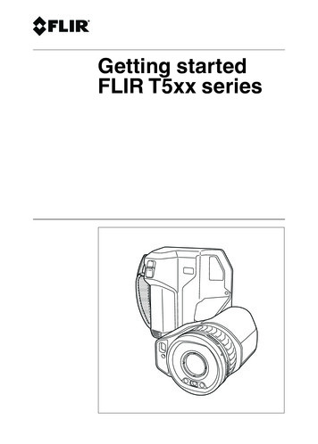
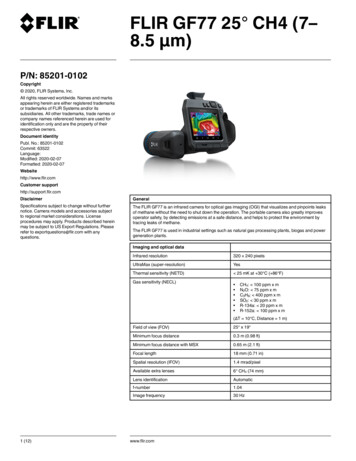
2 IllustrationsNote Explanations of the illustrations are provided in each language section.Figure 2.1 View from the rear: FLIR A400/A700Figure 2.2 View from the front: FLIR A400/A700#T810482; r. AA/64581/64581; mul2
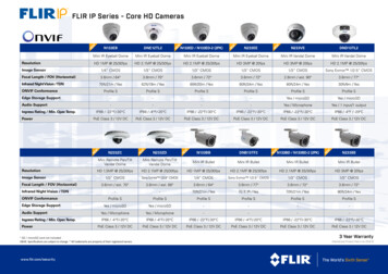
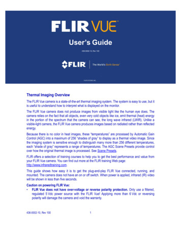
2 IllustrationsFigure 2.3 FLIR A400pt/A700ptFigure 2.4 FLIR A400f/A700fMQTTFigure 2.5 Example system overview: early fire detection#T810482; r. AA/64581/64581; mul3
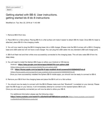
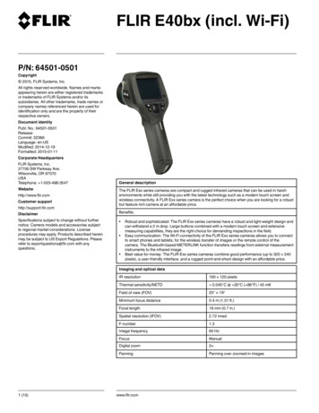
2 Illustrations6Figure 2.6 Example system overview: condition monitoring1243Figure 2.7 Example system overview: research and development#T810482; r. AA/64581/64581; mul4
3 EN-US English3.1 Read the manual before useGo to the following website to read or download 2 Extend your product warrantyRegister your product now to get: 2 years camera warrantyTo activate your extended warranty, go to http://support.flir.com/camreg.Note Registration must be completed within 60 days of purchase.3.3 Download FLIR softwareFLIR Systems provides freeware and licensed software for image editing, videoprocessing, thermal analysis, and reporting.To download FLIR Thermography software, go to http://www.flir.com/support.3.4 TrainingFor training resources and courses, go tohttp://www.flir.com/support-center/training.3.5 Customer supportDo not hesitate to contact our Customer Support Center at http://support.flir.comif you experience problems or have any questions about your product.#T810482; r. AA/64581/64581; mul5
3 EN-US English3.6 FLIR A400/A7003.6.1 Quick start guideYou can power the camera by using either the power I/O connector (18–56 V DC)or the Ethernet/power over Ethernet (PoE) connector (36–56 V DC) of the camera. See Figure 2.1 View from the rear: FLIR A400/A700, page 2.1.2.On the computer to be used for managing the camera, download FLIR IPConfig from http://support.flir.com, and then install it.Connect the camera to power and the network. Do one of the following:a.b.3.4.Connect the power cable between the camera and a power source (forpin configurations, refer to the user manual of the FLIR A400/A700 series). Connect the network cable to the camera, and then either directlyto the computer or to an Ethernet switch on the same network as thecomputer.Connect the PoE cable to the camera, and then to a PoE switch on thesame network as the computer.The camera is set to use DHCP. On the computer, use FLIR IP Config toidentify the camera on the network, and change the IP settings if necessary.On the computer, do one of the following:a.b.Double-click on the camera in FLIR IP Config.Type the IP address of your camera into the address bar of a webbrowser.This displays the login view.5.6.Log in using the provided username and password. This displays the web interface of the camera.Use the web interface to configure the camera. For Smart Sensor cameras,use the web interface to also add measurements and set alarms.3.6.2 View from the rearSee Figure 2.1 View from the rear: FLIR A400/A700, page 2.1.2.3.4.5.6.Power/error indicator LED (blue/red).Ethernet communication indicator LED (green).Ethernet/PoE connector, X-coded.Power I/O connector, A-coded.Antenna.RS232/485 connector, A-coded.#T810482; r. AA/64581/64581; mul6
3 EN-US English7.Factory reset button. For factory reset modes, refer to the user manual of theFLIR A400/A700 series.3.6.3 View from the frontSee Figure 2.2 View from the front: FLIR A400/A700, page 2.8. Infrared sensor.9. Visual camera.10. LED lamps.3.7 FLIR A400f/A700fWhen delivered, the camera is already mounted in an environmental housing.The housing with the camera requires PoE class 4 (25 W) to operate as intended.Connect the unit to power and the network:1.2.3.Connect a PoE cable (PoE class 4, 25 W) to the connector gland on the bottom of the housing device. Use the strain-relief clamp that is delivered withthe camera.Connect the other end of the PoE cable to a PoE switch.Follow the steps in section 3.6.1 Quick start guide, starting at step 3.3.8 FLIR A400pt/A700ptWhen delivered, the camera is already mounted in a pan/tilt (P/T) unit. The master selection mode is set to Camera Master, which means that the camera controls the P/T.Connect the unit to power and the network:1.2.3.4.5.6.Unscrew the two bolts in the cover to the base unit by using a 4 mm hex key.Pull a network cable and a power cable through either the parapet bracket orthe wall mount bracket.Pull both cables through the cable glands in the P/T base unit. Make surethat the cable glands are closed tightly.Connect the network cable to the RJ45 port, and the power cable to thepower port. Make sure to connect the AC power cable correctly. After the cables are connected, close the hatch and then tighten the bolts.Connect the network cable to a computer or an Ethernet switch, and connectthe power cable to a power source.Follow the steps in section 3.6.1 Quick start guide, starting at step 3.#T810482; r. AA/64581/64581; mul7
3 EN-US English7.In the web interface and on the tab Move camera, use the arrow buttons tocontrol the P/T device.3.9 Example system overviews3.9.1 Early fire detectionHot spot detection, self-combustible material on conveyor belt, see Figure 2.5Example system overview: early fire detection, page 3.1.2.3.4.5.6.7.8.9.10.Coal mine conveyor belt.FLIR A400/A700 Smart Sensor camera.Ethernet connector, X-coded.Power I/O connector, A-coded.Digital output to a programmable logic controller (PLC).Separate DIN rail power supply for galvanic isolation (18–56 V DC).Laptop used for set up of the camera using the web interface.Ethernet switch.MQTT output connected to a third-party cloud service.Example thermal mage.3.9.2 Condition monitoring24/7 Monitoring of critical assets, see Figure 2.6 Example system overview: condition monitoring, page 4.1.2.3.4.5.6.Computer running custom-made software.CAT 6 Ethernet cable.Industrial power over Ethernet (PoE) switch.FLIR A400/A700 Image Streaming cameras.Industrial process to be monitored, e.g., a gasifier.Example thermal image.3.9.3 Research and developmentChecking heat dissipation on a PCB during development, see Figure 2.7 Example system overview: research and development, page 4.1.2.3.4.Computer running FLIR science software, e.g., FLIR Research Studio.CAT 6 Ethernet cable.Laboratory setup with a FLIR A400/A700 Image Streaming camera.Example thermal image.#T810482; r. AA/64581/64581; mul8
4 DE-DE Deutsch4.1 Lesen Sie vor Gebrauch zunächst die AnleitungBesuchen Sie die folgende Website, um das Benutzerhandbuch zu lesen bzw. chxa4.2 Verlängern Sie die Garantie Ihres ProduktsRegistrieren Sie Ihr Produkt jetzt, und erhalten Sie: 2 Jahre Garantie auf die KameraUm Ihre erweiterte Garantie zu aktivieren, besuchen Sie die Seitehttp://support.flir.com/camreg.Hinweis Die Registrierung muss innerhalb von 60 Tagen nach Kauf abgeschlossen werden.4.3 FLIR Software herunterladenFLIR Systems bietet Freeware und lizenzierte Software für Bildbearbeitung, Videobearbeitung, thermische Analysen und Berichterstellung.Um FLIR Thermografie-Software herunterzuladen, besuchen Sie die Seitehttp://www.flir.com/support.4.4 SchulungSchulungsmaterial und Kurse finden Sie auf der .5 KundendienstWenn Probleme auftreten oder Sie Fragen zu unserem Produkt haben, wendenSie sich an unser Customer Support Center unter http://support.flir.com.#T810482; r. AA/64581/64581; mul9
4 DE-DE Deutsch4.6 FLIR A400/A7004.6.1 SchnelleinstiegZur Stromversorgung der Kamera können Sie entweder den I/O-Netzanschluss(18–56 V DC) oder den Ethernet-Anschluss (PoE, Power over Ethernet) (36–56 V DC) der Kamera verwenden. Siehe Figure 2.1 View from the rear: FLIRA400/A700, Seite 2.1.2.Um die Kamera zu verwalten, laden und installieren Sie FLIR IP Config vonder Website http://support.flir.com auf Ihrem Computer.Schließen Sie die Kamera an die Stromversorgung und das Netzwerk an.Führen Sie eine der folgenden Aktionen durch:a.b.3.4.Schließen Sie die Kamera über das Stromversorgungskabel an eineStromquelle an (weitere Informationen zu Steckerkonfigurationen findenSie im Benutzerhandbuch der FLIR A400/A700-Serie). Schließen Siedas Netzwerkkabel an die Kamera und entweder direkt an den Computer oder an einen Ethernet-Switch an, der sich im selben Netzwerk wieder Computer befindet.Schließen Sie das PoE-Kabel an die Kamera und einen PoE-Switch an,der sich im selben Netzwerk wie der Computer befindet.Die Kamera ist zur Verwendung von DHCP konfiguriert. Verwenden Sie aufdem Computer FLIR IP Config, um die Kamera im Netzwerk zu identifizieren,und ändern Sie ggf. die IP-Einstellungen.Führen Sie auf dem Computer eine der folgenden Aktionen aus:a.b.Doppelklicken Sie in FLIR IP Config auf die Kamera.Geben Sie die IP-Adresse Ihrer Kamera in die Adressleiste eines Webbrowsers ein.Dadurch wird die Ansicht „Anmelden“ angezeigt.5.6.Melden Sie sich mit dem bereitgestellten Benutzernamen und Passwort an.Dadurch wird die Webschnittstelle der Kamera angezeigt.Konfigurieren Sie die Kamera mithilfe Webschnittstelle. Verwenden Sie beiSmart Sensor-Kameras die Webschnittstelle, um auch Messungen hinzuzufügen und Alarme festzulegen.4.6.2 RückansichtSiehe Figure 2.1 View from the rear: FLIR A400/A700, Seite 2.1.LED-Netzanzeige/-Fehleranzeige (blau/rot).#T810482; r. AA/64581/64581; mul10
4 DE-DE Deutsch2.3.4.5.6.7.LED-Ethernet-Verbindungsanzeige (grün).Ethernet/PoE-Anschluss, X-codiert.I/O-Netzanschluss, A-codiert.Antenne.RS232/485-Anschluss, A-codiert.Taste zum Zurücksetzen auf Standardeinstellungen: Weitere Informationenzum Zurücksetzen auf die Werkseinstellungen finden Sie im Benutzerhandbuch der FLIR A400/A700-Serie.4.6.3 Ansicht von vornSiehe Figure 2.2 View from the front: FLIR A400/A700, Seite 2.8. Infrarotsensor.9. Tageslichtkamera.10. LED-Leuchten.4.7 FLIR A400f/A700fDie Kamera wird in einem Schutzgehäuse geliefert. Um die Kamera im Gehäuseordnungsgemäß zu bedienen, ist PoE-Klasse 4 (25 W) erforderlich.Schließen Sie das Gerät an die Stromversorgung und das Netzwerk an:1.2.3.Schließen Sie ein PoE-Kabel (PoE-Klasse 4, 25 W) an den Anschluss an derUnterseite des Kameragehäuses an. Verwenden Sie die im Lieferumfangder Kamera enthaltene Zugentlastungsklemme.Schließen Sie das andere Ende des PoE-Kabels an einen PoE-Switch an.Befolgen Sie die Schritte im Abschnitt 4.6.1 Schnelleinstieg, beginnend mitSchritt 3.4.8 FLIR A400pt/A700ptDie Kamera wird in einer Schwenk-/Neigeeinheit (P/T, Pan/Tilt) geliefert. Im Master-Auswahlmodus ist die Kamera als Master-Gerät eingestellt, d. h., die Kamera steuert die P/T.Schließen Sie das Gerät an die Stromversorgung und das Netzwerk an:1.2.Lösen Sie mit einem 4-mm-Innensechskantschlüssel die beiden Schraubenin der Abdeckung der Basis.Führen Sie ein Netzwerkkabel und ein Stromversorgungskabel entwederdurch die Geländerhalterung oder die Wandhalterung hindurch.#T810482; r. AA/64581/64581; mul11
4 DE-DE Deutsch3.4.5.6.7.Führen Sie beide Kabel durch die Kabelverschraubungen in der P/T-Basishindurch. Vergewissern Sie sich, dass die Kabelverschraubungen fest zugezogen sind.Schließen Sie das Netzwerkkabel an den RJ45-Anschluss und das Stromversorgungskabel an den Netzanschluss an. Vergewissern Sie sich, dassdas Stromversorgungskabel richtig angeschlossen ist. Nachdem die Kabelangeschlossen wurden, schließen Sie die Klappe und ziehen Sie dieSchrauben fest.Schließen Sie das Netzwerkkabel an einen Computer oder einen EthernetSwitch und das Stromversorgungskabel an eine Stromquelle an.Befolgen Sie die Schritte im Abschnitt 4.6.1 Schnelleinstieg, beginnend mitSchritt 3.Verwenden Sie die Pfeiltasten in der Webschnittstelle bzw. auf der Registerkarte Move camera, um das P/T-Gerät zu steuern.4.9 Beispielsystemübersichten4.9.1 Frühzeitige BranderkennungZur Hotspot-Erkennung und brennbaren Materialien auf dem Förderband siehe Figure 2.5 Example system overview: early fire detection, Seite R A400/A700 Smart Sensor-Kamera.Ethernet-Anschluss, X-codiert.I/O-Netzanschluss, A-codiert.Digitaler Ausgang zu einer speicherprogrammierbaren Steuerung (SPS).Separates Hutschienen-Netzteil für galvanische Trennung (18–56 V DC).Laptop zur Einrichtung der Kamera über die Webschnittstelle.Ethernet-Switch.MQTT-Ausgabe, die mit einem Drittanbieter-Cloud-Service verbunden ist.Beispielwärmebild.4.9.2 ZustandsüberwachungZur Überwachung kritischer Anlagen rund um die Uhr siehe Figure 2.6 Examplesystem overview: condition monitoring, Seite 4.1.2.3.4.Computer mit speziell entwickelter Software.CAT-6-Ethernet-Kabel.Industrieller Power-over-Ethernet-Switch (PoE).FLIR A400/A700 Image Streaming-Kameras.#T810482; r. AA/64581/64581; mul12
4 DE-DE Deutsch5.6.Zu überwachender Industrieprozess, z. B. ein Vergaser.Beispielwärmebild.4.9.3 Forschung und EntwicklungZur Prüfung der Wärmeableitung auf einer Leiterplatte während der Entwicklungsphase siehe Figure 2.7 Example system overview: research and development, Seite 4.1.2.3.4.Computer mit FLIR Science-Software, z. B. FLIR Research Studio.CAT-6-Ethernet-Kabel.Laboreinrichtung mit einer FLIR A400/A700 Image Streaming-Kamera.Beispielwärmebild.#T810482; r. AA/64581/64581; mul13
5 ES-ES Español5.1 Lea el manual antes de usar el productoVisite el siguiente sitio web para leer o descargar elmanual:http://support.flir.com/resources/chxa5.2 Amplíe la garantía de sus productosRegistre su producto ahora y obtendrá: 2 años de garantía en cámarasPara activar la ampliación de la garantía, vaya a http://support.flir.com/camregNota El registro debe completarse dentro de los primeros 60 días de la compra.5.3 Descargar software de FLIRFLIR Systems proporciona software gratuito y software con licencia para ediciónde imagen, procesamiento de vídeo, análisis térmico y generación de informes.Para descargar el software de termografía de FLIR, vaya ahttp://www.flir.com/support5.4 FormaciónPara recursos de formación y cursos, vaya ahttp://www.flir.com/support-center/training5.5 Atención al clienteNo dude en ponerse en contacto con nuestro centro de soporte técnico enhttp://support.flir.com si tiene problemas o alguna pregunta referente a suproducto.#T810482; r. AA/64581/64581; mul14
5 ES-ES Español5.6 FLIR A400/A7005.6.1 Guía de inicio rápidoPuede activar la cámara mediante el conector de alimentación de E/S (18-56 VCC) o el conector Ethernet/de alimentación a través de Ethernet (PoE) (36-56 VCC) de la cámara. Consulte la Figure 2.1 View from the rear: FLIR A400/A700,página 2.1.2.En el equipo que se va a utilizar para gestionar la cámara, descargue FLIRIP Config de http://support.flir.com, y, a continuación, instálelo.Conecte la cámara a la alimentación y a la red. Realice una de las siguientesacciones:a.b.3.4.Conecte el cable de alimentación a la cámara y a una fuente de alimentación (para la configuración de los pines, consulte el manual de usuariode la serie FLIR A400/A700). Conecte el cable de red a la cámara y, acontinuación, directamente al equipo o a un interruptor Ethernet que esté conectado a la misma red que el equipo.Conecte el cable PoE a la cámara y, a continuación, a un interruptorPoE que esté conectado a la misma red que el equipo.La cámara está configurada para utilizar el DHCP. En el equipo, utilice FLIRIP Config para identificar la cámara en la red y cambie la configuración de laIP si es necesario.En el equipo, realice una de las siguientes acciones:a.b.Haga doble clic en la cámara, en FLIR IP Config.Escriba la dirección IP de su cámara en la barra de direcciones de unnavegador web.Esto mostrará la vista de inicio de sesión.5.6.Inicie sesión con el nombre de usuario y contraseña proporcionados. Estomostrará la interfaz web de la cámara.Utilice la interfaz web para configurar la cámara. En el caso de las cámarasSmart Sensor, también puede utilizar la interfaz web para añadir medidas yestablecer alarmas.5.6.2 Vista desde la parte posteriorConsulte la Figure 2.1 View from the rear: FLIR A400/A700, página 2.1.2.Indicador LED de alimentación/error (azul/rojo).Indicador LED de comunicación Ethernet (verde).#T810482; r. AA/64581/64581; mul15
5 ES-ES Español3.4.5.6.7.Conector Ethernet/PoE, codificación X.Conector de alimentación de E/S, codificación A.Antena.Conector RS232/485, codificación A.Botón de restablecimiento de la configuración de fábrica. Para obtener información sobre los modos de restablecimiento de la configuración de fábrica,consulte el manual de usuario de la serie FLIR A400/A700.5.6.3 Vista desde la parte delanteraConsulte la Figure 2.2 View from the front: FLIR A400/A700, página 2.8. Sensor de infrarrojos.9. Cámara visual.10. Luces LED.5.7 FLIR A400f/A700fCuando se entrega, la cámara ya viene montada en una carcasa de protecciónambiental. La carcasa junto con la cámara requieren PoE de clase 4 (25 W) paraque funcionen como está previsto.Conecte la unidad a la alimentación y a la red:1.2.3.Conecte un cable PoE (PoE de clase 4, 25 W) al prensaestopas del conectorsituado en la parte inferior del dispositivo de protección. Utilice la abrazadera de liberación de tensión que se suministra con la cámara.Conecte el otro extremo del cable PoE al interruptor PoE.Siga los pasos de la sección 5.6.1 Guía de inicio rápido. Comience por el paso 3.5.8 FLIR A400pt/A700ptCuando se entrega, la cámara ya viene montada en una unidad de giro/inclinación (P/T). El modo de selección de control se encuentra en "Camera Master", loque significa que la cámara controla la unidad de P/T.Con
3.3 Download FLIR software FLIR Systems provides freeware and licensed software for image editing, video processing, thermal analysis, and reporting. . MQTT output connected to a third-party cloud service. 10. Example thermal mage. 3.9.2 Condition monitoring 24/7 Monitoring of critical