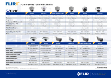
Transcription
User’s Guide436-0002-10, Rev 100Thermal Imaging OverviewThe FLIR Vue camera is a state-of-the-art thermal imaging system. The system is easy to use, but itis useful to understand how to interpret what is displayed on the monitor.The FLIR Vue camera does not produce images from visible light like the human eye does. Thecamera relies on the fact that all objects, even very cold objects like ice, emit thermal (heat) energyin the portion of the spectrum that the camera can see, the long wave infrared (LWIR). Unlike avisible-light camera, the FLIR Vue camera produces images based on radiated rather than reflectedenergy.Because there is no color in heat images, these “temperatures” are processed by Automatic GainControl (AGC) into a maximum of 256 “shades of gray” to display as a thermal video image. Sincethe imaging system is sensitive enough to distinguish many more than 256 different temperatures,each “shade of gray” represents a range of temperatures. The AGC Scene Presets provide controlover how the original thermal image is processed. See Scene Presets.FLIR offers a selection of training courses to help you to get the best performance and value fromyour FLIR Vue camera. You can find out more at the FLIR training Web page:http://www.infraredtraining.com.This guide shows how easy it is to get the plug-and-play FLIR Vue connected, running, andmounted. The camera does not have an on or off switch. When power is applied, infrared (IR) videowill be shown in less than five seconds.Caution on powering FLIR Vue: FLIR Vue does not have over-voltage or reverse polarity protection. Only use a filtered,regulated 5 Vdc power source with the FLIR Vue! Applying more than 6 Vdc or reversingpolarity will damage the camera and void the warranty.436-0002-10, Rev 1001
What’s in the Box?FLIR Vue comes with the following components: FLIR Vue thermal camera with camera mount.Camera Body¼-20 ThreadedMounting HoleLens BarrelM2X0.4 threaded mounting holes onthe camera’s left side, right side, andbottom (mounting screws not included) LensCamera Mount10-pin mini-USBconnectorBench Cable—for connecting FLIR Vue to a computer USB port and a video monitor for testingand configuring camera options.Connect toVideo MonitorConnect to Camera10-pin mini-USB portConnect toComputer USB portMounting FLIR VueFLIR Vue has a variety of mounting options.¼-20 InsertScrew a standard tripod ¼-20 bolt into the threaded insertlocated on the top surface of the camera. Do not exceed6.35 mm [0.25 in] maximum depth or warranty will be void.FLIR Vue has two threaded mounting holes on each side, aswell as on the camera bottom.These threaded holes, 24 mm (0.945 in) apart accept M2x0.4screws (not included). Do not exceed 4.0 mm [0.157 in]maximum depth or warranty is void.436-0002-10, Rev 1002Side and BottomMounting Holes
Camera MountThe included Camera Mount allows using standard action camera mounts. If a different mountingoption will be used, it can be removed using the following steps:Unscrew the Lens NutSlide the Camera Mount offScrew the Lens Nut back onWhen installing the Camera Mount, be sure to engage the two alignment pins with thecorresponding holes on the camera body.Connecting and Powering the FLIR VueFLIR Vue is compatible with common 10-pin mini-USB cables that are used to provide power to, andget video from, a camera mounted on a small unmanned aerial system (sUAS).A couple of examples are shown below.A number of vendors sell cables compatible with video transmitters which supply the 5 Vdc, 500 mApower the FLIR Vue needs. Connect the video transmitter per the manufacturer’s instructions.10-pin Mini USB plugPin 2Pin 2 – 5 Vdc power inPin 5 – Video GNDPin 7 – Video OutPin 10 – groundVideo Transmitter cable:White – not usedYellow – Video OutBlack – groundRed – 5 Vdc power inPin 5Pin 7Pin 10Another example of a compatible cable which provides discrete connectors for power and video isshown below.Discrete Power/Video connectorsPin 2Video OutVideo GNDPin 5Pin 7Pin 10436-0002-10, Rev 10035 Vdc power inPower ground
Installing the FLIR sUAS Camera Controller GUIFollow the instructions for downloading the Camera Controller GUI from the FLIR website:www.flir.com/flirvue. Scroll down to the “DOWNLOAD THE GUI” link; fill in and submit the form toreceive an email with a download link.1. Extract the files using WinZip or other software.2. Open the directory with the extracted files and double-click setup.exe.3. When the primary installation is completed, a message will prompt to install Silicon Laboratoriesdrivers. This is necessary for using a USB connection to the camera.Connecting to the FLIR sUAS Camera Controller GUIWhen power is applied, the FLIR Vue camera will provide video output without any additional setupor configuration. Use the sUAS GUI to fine tune the configuration for specific operating scenarios.The camera should be connected and powered before starting the sUAS GUI.1. Using the Bench cable, connect the FLIR Vue tothe USB port on the computer and a video monitor.When powered on, the FLIR flash screen willappear while the camera boots and then infraredvideo will be displayed.2. To start the program go to: Start All Programs FLIR Systems Camera ControllerGUI. The first time the GUI is started, select thecamera type at the prompt.3. Choose Camera ConnectIf the camera does not connect automatically,choose to display the connection wizard and followthe prompts.436-0002-10, Rev 1004
FLIR sUAS Camera Controller GUIThe sUAS Camera Controller screen is divided into two sections: Camera Setup—These functions, described below, provide for orientation options, video format,zoom, colorization, and recovery to factory or power up settings. Video Performance—Select an Automatic Gain Control (AGC) Scene Preset depending on theanticipated imaging subject and environment. The default Region of Interest (ROI) is set toexclude open sky from the AGC adjustments. The sky is very cold which skews the AGC intosettings for a much colder scene than may be desired.Camera Setup OrientationInvert—Use this function to flip the video image vertically. If the camera ismounted upside down, use both Invert and Revert.Revert—Use this function to flip the video image horizontally. If thecamera is mounted to provide a rear view mirror image use Revert. Video Standard—FLIR Vue can output video in either NTSC or PALformat. The video standard must match the video monitor or videorecording devices. Digital Zoom—FLIR Vue can be set to any digitalzoom setting up to 8x.436-0002-10, Rev 1005
Camera Setup buttonsSave Settings—Save all of the current settingsof the camera to be used during a power up orsoftware reset.Factory Defaults—Return all camera settingsto the initial values set at the factory.Do FFC—manually initiates a flat fieldcorrection (FFC) that updates the pixelcalibration to improve image quality. An internalshutter is closed (a click can be heard) behindthe lens to provide a uniform temperature to allpixels. FFC is also performed automatically,based on elapsed time and during changes intemperature.Reset Camera—Causes a reboot of thecamera software. Polarity / PaletteWhiteHot and BlackHot are the primary palettes usedin thermal imaging. The image has been described ascontaining 256 “shades of gray” each representing adifferent temperature range present in the scene. Avariety of color palettes may provide better contrastwhen viewed with the naked eye, under certainconditions. Different color palettes can provide verydifferent results in the image. Their appeal is based onpersonal preference.InstAlert and Arctic are special purpose searchpalettes that emphasize the high or low temperatureranges. InstAlert shows high ranges in red-orangeshades, lower ranges in gray. Useful for searching foranimals obscured by dark or camouflage. Arctic showslow ranges in blue shades, higher ranges in gray. Usefulfor searching for cold areas in a hot scene.436-0002-10, Rev 1006
Video Performance Scene PresetsEach Scene Preset provides a combination of Automatic Gain Control (AGC)settings which have been optimized by FLIR Systems to provide the bestimage for each particular application. In most cases these Scene Presets willbe all the camera setup required. These settings may appear as changes inbrightness, sharpness and contrast, although in IR imaging the effects arequite different and change over time and scene temperature. Region of InterestThe region of interest (ROI) is the portion of the scene used by the AGC to calculate the AGCsettings. The default ROI, shown below, makes the assumption that the camera is mounted lookingforward so that some of the sky will be in the scene. The sky is generally very cold and uniform, notradiating heat. In this case the ROI includes only the lower portion of the scene, the ground, whichwill have more contrasting radiated heat, areas of different temperatures.1. Change size and location.2. Set Region of Interest.Default ROI—The AGC will use scene settingsthat maximize the contrast of heat radiation onthe ground without including the large area ofcold sky. Higher temperature object in the upperportion of the scene will still be seen, but will notcause changes to the AGC settings.Use the bubbles on the corners or sides of thehighlighted ROI and drag to change the size;drag in the center to reposition the region.When finished, click the Set Region of Interestbutton, then Save Settings.3. Save Settings4. Confirm436-0002-10, Rev 1007
FLIR Vue SpecificationsOverviewThermal ImagerUncooled VOx MicrobolometerResolutionLens OptionsSpectral Band640x512336x2569 mm; 69 x 56 13 mm; 45 x 37 19 mm; 32 x 26 6.8 mm; 45 x 35 9 mm; 35 x 27 13 mm; 25 x 19 7.5 μm - 13.5 μmFull Frame Rates30 Hz (NTSC); 25 Hz (PAL) US only, not for ExportExportable Frame Rates7.5 Hz (NTSC); 8.3 Hz (PAL)Physical AttributesSize2.26" x 1.75" (57.4 mm x 44.5 mm) (including lens)Weight3.25 oz to 4.0 oz (92.1 g to 113.4 g) configuration dependentImage Processing & Display ControlsImage Optimization for sUASYesDigital Detail EnhancementYes - Adjustable in GUIInvertable ImageYes - Adjustable in GUIPolarity Control (BlackHot/WhiteHot) and Color PalettesYes - Adjustable in GUIPowerInput Supply Voltage4.0 Vdc to 6.0 VdcPower Dissipation, steady state (max 2.5 W duringshutter event of approximately 0.5 seconds) 1.2 W 1.0 WEnvironmentalOperating Temperature Range-20 C to 50 CNon-Operating Temperature Range-55 C to 95 COperational Altitude 40,000 feetCARE OF FLIR Vue Only power FLIR Vue with a regulated 5 Vdc power source. Using more than 6 Vdc will damagethe camera and void the warranty. Do not touch the lens. If the lens gets dirty, a light dusting of air should dislodge any dustparticles. If the lens is still noticeably dirty, use 75% Isopropyl alcohol and lens tissue. Use alight wiping motions with a fresh section of lens tissue with each swipe so as not to drag dust ordirt particles back over the lens surface FLIR Vue is neither water nor dust resistant. Care for it as you would any valuable piece ofelectronics equipment.436-0002-10, Rev 100
FLIR Vue thermal camera with camera mount. Bench Cable—for connecting FLIR Vue to a computer USB port and a video monitor for testing and configuring camera options. Mounting FLIR Vue FLIR Vue has a variety of mounting options. Screw a standard tripod ¼-20 bolt into the threaded in