Transcription
25.00 U.S.ACS 500Programming ManualIncluding Application MacrosACS 500 Adjustable FrequencyAC Drives 1 to 400 HP, Series BACS 500-05CEFFECTIVE 9/1/94SUPERCEDES 6/1/94ABB DrivesASEA BROWN BOVERI
Safety InstructionsGeneral SafetyInstructionsWarnings in this manual appear in either of two ways: Dangerous voltage warnings, preceded by a Dangerous Voltage symbol,indicate the presence of voltages which may cause death or serious injury.These warnings describe procedures to avoid death or serious injury. General warnings, preceded by a General Warning symbol, indicatesituations or conditions which may cause death or serious injury. Thesewarnings describe procedures to avoid death or serious injury.CAUTIONS inform you of situations or conditions which will damagemachinery or cause additional motor-operation down-time if you do not takesuggested steps to correct or address such situations or conditions.Note: Notes provide you with additional and useful information. Althoughless urgent than cautions and warnings, notes are important and shouldnot be ignored.Warning SymbolsFor your own safety please pay special attention to instructions containingthese symbols:This warning symbol indicates the presence of dangerous voltage.This symbol informs you of high voltage conditions, situations, andlocations that may cause death or serious injury if you do notfollow precautions and proper steps.This warning symbol indicates a general warning.This warning symbol indicates an electrostatic discharge hazard.ACS 500 Programming Manualiii
Safety InstructionsWarnings, Cautions,and NotesWARNING! Your drive contains dangerous voltages when connected to theline power. Always check that the ACS 500 is safe, after disconnecting thepower, by measuring the DC bus voltage and line input voltage. Failure tocheck voltages could cause death or serious injury. Only a qualified electricianshould carry out the electrical installation.Note that the Motor Control Card of the ACS 500 is at DC bus voltagepotential.The DC bus capacitors contain dangerous DC voltage levels (1.35 x VIN).After disconnecting the supply, wait at least five minutes after the displayreadout on the control panel has disappeared before taking any measurements.Dangerous external control voltages may be present on the relay outputs ofthe Control Interface Card and Option Cards.CAUTION: Electrostatic Discharge (ESD) can damage electronic circuits.Do not handle any components without following the proper ESDprecautions.ivACS 500 Programming Manual
Table of ContentsChapter 1 – IntroductionHow To Use This Manual . . . . . . . . . . . . . . . . . . . . . . . . . . . . . . . . . . . . . . . . . . . . . . . . . . . . . . . . . .Intended Audience . . . . . . . . . . . . . . . . . . . . . . . . . . . . . . . . . . . . . . . . . . . . . . . . . . . . . . . . . . . . . . . .Conventions Used In This Manual . . . . . . . . . . . . . . . . . . . . . . . . . . . . . . . . . . . . . . . . . . . . . . . . . . .Control Panel Display . . . . . . . . . . . . . . . . . . . . . . . . . . . . . . . . . . . . . . . . . . . . . . . . . . . . . . . . . .Control Panel Keys . . . . . . . . . . . . . . . . . . . . . . . . . . . . . . . . . . . . . . . . . . . . . . . . . . . . . . . . . . . .Related Publications . . . . . . . . . . . . . . . . . . . . . . . . . . . . . . . . . . . . . . . . . . . . . . . . . . . . . . . . . . . . . .1-11-21-21-21-31-3Chapter 2 – Overview of ACS 500 ProgrammingOverview of Application Macros . . . . . . . . . . . . . . . . . . . . . . . . . . . . . . . . . . . . . . . . . . . . . . . . . . . .Application Macros Defined . . . . . . . . . . . . . . . . . . . . . . . . . . . . . . . . . . . . . . . . . . . . . . . . . . . . .Menu System of Parameters . . . . . . . . . . . . . . . . . . . . . . . . . . . . . . . . . . . . . . . . . . . . . . . . . . . . . . . .Start-up Data Parameters . . . . . . . . . . . . . . . . . . . . . . . . . . . . . . . . . . . . . . . . . . . . . . . . . . . . . . . .Operating Data Parameters . . . . . . . . . . . . . . . . . . . . . . . . . . . . . . . . . . . . . . . . . . . . . . . . . . . . . .Menu Navigation . . . . . . . . . . . . . . . . . . . . . . . . . . . . . . . . . . . . . . . . . . . . . . . . . . . . . . . . . . . . . .2-12-12-22-22-32-3Chapter 3 – Start-up DataStart-up Data Parameters . . . . . . . . . . . . . . . . . . . . . . . . . . . . . . . . . . . . . . . . . . . . . . . . . . . . . . . . . . . 3-1Overview . . . . . . . . . . . . . . . . . . . . . . . . . . . . . . . . . . . . . . . . . . . . . . . . . . . . . . . . . . . . . . . . . . . . 3-1Parameter Selection . . . . . . . . . . . . . . . . . . . . . . . . . . . . . . . . . . . . . . . . . . . . . . . . . . . . . . . . . . . . 3-2Chapter 4 – Control OperationOperating Data Parameters . . . . . . . . . . . . . . . . . . . . . . . . . . . . . . . . . . . . . . . . . . . . . . . . . . . . . . . . . 4-1Overview . . . . . . . . . . . . . . . . . . . . . . . . . . . . . . . . . . . . . . . . . . . . . . . . . . . . . . . . . . . . . . . . . . . . 4-1Parameter Selection . . . . . . . . . . . . . . . . . . . . . . . . . . . . . . . . . . . . . . . . . . . . . . . . . . . . . . . . . . . . 4-3Motor Control Values . . . . . . . . . . . . . . . . . . . . . . . . . . . . . . . . . . . . . . . . . . . . . . . . . . . . . . . . . . 4-6Keypad Control vs. External Control . . . . . . . . . . . . . . . . . . . . . . . . . . . . . . . . . . . . . . . . . . . . . . . . . 4-7Keypad Control . . . . . . . . . . . . . . . . . . . . . . . . . . . . . . . . . . . . . . . . . . . . . . . . . . . . . . . . . . . . . . . 4-7External Control . . . . . . . . . . . . . . . . . . . . . . . . . . . . . . . . . . . . . . . . . . . . . . . . . . . . . . . . . . . . . . . 4-7Keypad Reference 1 and Keypad PI . . . . . . . . . . . . . . . . . . . . . . . . . . . . . . . . . . . . . . . . . . . . . . . 4-9External Reference 1 and 2 . . . . . . . . . . . . . . . . . . . . . . . . . . . . . . . . . . . . . . . . . . . . . . . . . . . . . 4-10Password Protection (Parameter Lock) . . . . . . . . . . . . . . . . . . . . . . . . . . . . . . . . . . . . . . . . . . . . . . . 4-10Chapter 5 – Standard Application Macro ProgramsUser Macro . . . . . . . . . . . . . . . . . . . . . . . . . . . . . . . . . . . . . . . . . . . . . . . . . . . . . . . . . . . . . . . . . . . . .Macro Applications and Access . . . . . . . . . . . . . . . . . . . . . . . . . . . . . . . . . . . . . . . . . . . . . . . . . . . . .Application 1 – Factory Macro . . . . . . . . . . . . . . . . . . . . . . . . . . . . . . . . . . . . . . . . . . . . . . . . . . . . . .Operation Diagram . . . . . . . . . . . . . . . . . . . . . . . . . . . . . . . . . . . . . . . . . . . . . . . . . . . . . . . . . . . . .Input and Output Signals . . . . . . . . . . . . . . . . . . . . . . . . . . . . . . . . . . . . . . . . . . . . . . . . . . . . . . . .Factory Macro External Connections . . . . . . . . . . . . . . . . . . . . . . . . . . . . . . . . . . . . . . . . . . . . . . .Factory Macro Parameter Settings . . . . . . . . . . . . . . . . . . . . . . . . . . . . . . . . . . . . . . . . . . . . . . . . .ACS 500 Programming Manual5-15-25-35-35-35-45-5v
Table of ContentsApplication 2 – Hand/Auto Control . . . . . . . . . . . . . . . . . . . . . . . . . . . . . . . . . . . . . . . . . . . . . . . . . . . 5-6Operation Diagram . . . . . . . . . . . . . . . . . . . . . . . . . . . . . . . . . . . . . . . . . . . . . . . . . . . . . . . . . . . . . 5-6Input and Output Signals . . . . . . . . . . . . . . . . . . . . . . . . . . . . . . . . . . . . . . . . . . . . . . . . . . . . . . . . 5-6Hand/Auto External Connections . . . . . . . . . . . . . . . . . . . . . . . . . . . . . . . . . . . . . . . . . . . . . . . . . . 5-7Hand/Auto Parameter Settings . . . . . . . . . . . . . . . . . . . . . . . . . . . . . . . . . . . . . . . . . . . . . . . . . . . . 5-8Application 3 – PI Control . . . . . . . . . . . . . . . . . . . . . . . . . . . . . . . . . . . . . . . . . . . . . . . . . . . . . . . . . . 5-9Operation Diagram . . . . . . . . . . . . . . . . . . . . . . . . . . . . . . . . . . . . . . . . . . . . . . . . . . . . . . . . . . . . . 5-9Input and Output Signals . . . . . . . . . . . . . . . . . . . . . . . . . . . . . . . . . . . . . . . . . . . . . . . . . . . . . . . . 5-9PI Control External Connections . . . . . . . . . . . . . . . . . . . . . . . . . . . . . . . . . . . . . . . . . . . . . . . . . 5-10PI Control Parameter Settings . . . . . . . . . . . . . . . . . . . . . . . . . . . . . . . . . . . . . . . . . . . . . . . . . . . 5-11Application 4 – Opt. Pack . . . . . . . . . . . . . . . . . . . . . . . . . . . . . . . . . . . . . . . . . . . . . . . . . . . . . . . . . 5-12Operation Diagram . . . . . . . . . . . . . . . . . . . . . . . . . . . . . . . . . . . . . . . . . . . . . . . . . . . . . . . . . . . . 5-12Input and Output Signals . . . . . . . . . . . . . . . . . . . . . . . . . . . . . . . . . . . . . . . . . . . . . . . . . . . . . . . 5-12Opt. Pack External Connections . . . . . . . . . . . . . . . . . . . . . . . . . . . . . . . . . . . . . . . . . . . . . . . . . . 5-13Opt. Pack Parameter Settings . . . . . . . . . . . . . . . . . . . . . . . . . . . . . . . . . . . . . . . . . . . . . . . . . . . . 5-14Application 5 – Seq Ctrl . . . . . . . . . . . . . . . . . . . . . . . . . . . . . . . . . . . . . . . . . . . . . . . . . . . . . . . . . . 5-15Operation Diagram . . . . . . . . . . . . . . . . . . . . . . . . . . . . . . . . . . . . . . . . . . . . . . . . . . . . . . . . . . . . 5-15Input and Output Signals . . . . . . . . . . . . . . . . . . . . . . . . . . . . . . . . . . . . . . . . . . . . . . . . . . . . . . . 5-15Seq Ctrl External Connections . . . . . . . . . . . . . . . . . . . . . . . . . . . . . . . . . . . . . . . . . . . . . . . . . . . 5-16Seq Ctrl Parameter Settings . . . . . . . . . . . . . . . . . . . . . . . . . . . . . . . . . . . . . . . . . . . . . . . . . . . . . 5-17Application 6 – Pump and Fan . . . . . . . . . . . . . . . . . . . . . . . . . . . . . . . . . . . . . . . . . . . . . . . . . . . . . . 5-18Operation Diagram . . . . . . . . . . . . . . . . . . . . . . . . . . . . . . . . . . . . . . . . . . . . . . . . . . . . . . . . . . . . 5-18Input and Output Signals . . . . . . . . . . . . . . . . . . . . . . . . . . . . . . . . . . . . . . . . . . . . . . . . . . . . . . . 5-18Pump and Fan External Connections . . . . . . . . . . . . . . . . . . . . . . . . . . . . . . . . . . . . . . . . . . . . . . 5-19Pump and Fan Parameter Settings . . . . . . . . . . . . . . . . . . . . . . . . . . . . . . . . . . . . . . . . . . . . . . . . 5-20Chapter 6 – ParametersACS 500 Parameter Menus . . . . . . . . . . . . . . . . . . . . . . . . . . . . . . . . . . . . . . . . . . . . . . . . . . . . . . . . . 6-1ACS 500 Parameters . . . . . . . . . . . . . . . . . . . . . . . . . . . . . . . . . . . . . . . . . . . . . . . . . . . . . . . . . . . . . . 6-1Main 10 Control Connections . . . . . . . . . . . . . . . . . . . . . . . . . . . . . . . . . . . . . . . . . . . . . . . . . . . . . . . 6-2Group 10.1 Start/Stop/Direction . . . . . . . . . . . . . . . . . . . . . . . . . . . . . . . . . . . . . . . . . . . . . . . . . . . 6-2Group 10.2 Ext Reference Select . . . . . . . . . . . . . . . . . . . . . . . . . . . . . . . . . . . . . . . . . . . . . . . . . . 6-4Group 10.3 Preset Speeds . . . . . . . . . . . . . . . . . . . . . . . . . . . . . . . . . . . . . . . . . . . . . . . . . . . . . . . . 6-7Group 10.4 System Contr Inputs . . . . . . . . . . . . . . . . . . . . . . . . . . . . . . . . . . . . . . . . . . . . . . . . . . 6-9Group 10.5 Analog Inputs . . . . . . . . . . . . . . . . . . . . . . . . . . . . . . . . . . . . . . . . . . . . . . . . . . . . . . 6-10Group 10.6 Relay Outputs . . . . . . . . . . . . . . . . . . . . . . . . . . . . . . . . . . . . . . . . . . . . . . . . . . . . . . 6-12Group 10.7 Analog Outputs . . . . . . . . . . . . . . . . . . . . . . . . . . . . . . . . . . . . . . . . . . . . . . . . . . . . . 6-14Group 10.8 Ext Communication . . . . . . . . . . . . . . . . . . . . . . . . . . . . . . . . . . . . . . . . . . . . . . . . . . 6-16Main 20 Drive Parameters . . . . . . . . . . . . . . . . . . . . . . . . . . . . . . . . . . . . . . . . . . . . . . . . . . . . . . . . . 6-16Group 20.2 Start/Stop . . . . . . . . . . . . . . . . . . . . . . . . . . . . . . . . . . . . . . . . . . . . . . . . . . . . . . . . . . 6-17Group 20.3 Accel/Decel . . . . . . . . . . . . . . . . . . . . . . . . . . . . . . . . . . . . . . . . . . . . . . . . . . . . . . . . 6-20Group 20.4 Motor Control . . . . . . . . . . . . . . . . . . . . . . . . . . . . . . . . . . . . . . . . . . . . . . . . . . . . . . 6-22Group 20.5 Crit Frequencies . . . . . . . . . . . . . . . . . . . . . . . . . . . . . . . . . . . . . . . . . . . . . . . . . . . . . 6-28Main 30 Protection Parameters . . . . . . . . . . . . . . . . . . . . . . . . . . . . . . . . . . . . . . . . . . . . . . . . . . . . . 6-30Group 30.1 Fault Function . . . . . . . . . . . . . . . . . . . . . . . . . . . . . . . . . . . . . . . . . . . . . . . . . . . . . . 6-30Group 30.2 Automatic Reset . . . . . . . . . . . . . . . . . . . . . . . . . . . . . . . . . . . . . . . . . . . . . . . . . . . . 6-37Group 30.3 Supervision . . . . . . . . . . . . . . . . . . . . . . . . . . . . . . . . . . . . . . . . . . . . . . . . . . . . . . . . 6-38Group 30.4 Information . . . . . . . . . . . . . . . . . . . . . . . . . . . . . . . . . . . . . . . . . . . . . . . . . . . . . . . . 6-40viACS 500 Programming Manual
Table of ContentsMain 40 Application Parameters . . . . . . . . . . . . . . . . . . . . . . . . . . . . . . . . . . . . . . . . . . . . . . . . . . . . 6-41Group 40.1 PI-Controller . . . . . . . . . . . . . . . . . . . . . . . . . . . . . . . . . . . . . . . . . . . . . . . . . . . . . . . 6-41Group 40.2 Pump & Fan Control . . . . . . . . . . . . . . . . . . . . . . . . . . . . . . . . . . . . . . . . . . . . . . . . . 6-45Appendix A – Complete Parameter Settings. . . . . . . . . . . . . . . . . . . . . . . . . . . . . . . . . . . . .A-1Appendix B – Programming Digital Inputs . . . . . . . . . . . . . . . . . . . . . . . . . . . . . . . . . . . . . .B-1Index . . . . . . . . . . . . . . . . . . . . . . . . . . . . . . . . . . . . . . . . . . . . . . . . . . . . . . . . . . . . . . . . . . . . . I-1ACS 500 Programming Manualvii
Table of ContentsThis page intentionally left blank.viiiACS 500 Programming Manual
Chapter 1 – IntroductionThis chapter describes the purpose and contents of this manual, describes theintended audience, explains conventions used in this manual, and lists relatedpublications.How To Use ThisManualThe purpose of this manual is to provide you with the information necessaryto select, modify, and apply Application macros to the operation of your ACS500 drive.ACS 500 user documentation also includes either the ACS 501 Installation &Start-up Manual or the ACS 502 Installation & Start-up Manual, which isincluded with the drive.Chapter 1 – Introduction, the chapter you are reading now, introduces you tothe ACS 500 Adjustable Frequency AC Drives Programming ManualIncluding Application Macros and conventions used throughout the manual.Chapter 2 – Overview of ACS 500 Programming provides an overview ofApplication macros and describes how to use the menu system of parametersto select and modify the macros.Chapter 3 – Start-up Data lists and explains the Start-up Data parameters. Thischapter also describes how to set the Start-up Data parameters.Chapter 4 – Control Operation describes operating data parameters, keypadreferences, drive-mounted and external controls, setting parameters for yourspecific drive application, and protecting your drive parameters fromunauthorized changes.Chapter 5 – Standard Application Macro Programs defines Applicationmacros in terms of parameter settings. This chapter also describes theoperation and application suitability of six standard Application macros andthe User macro.Chapter 6 – Parameters lists the ACS 500 parameters and explains thefunctions of each parameter.Appendix A – Complete Parameter Settings lists, in a table form, all parametersettings for the ACS 500.Appendix B – Programming Digital Inputs DI1 – DI6 lists, in table form,parameter values and digital I/O configurations.Index helps you locate the page numbers of topics contained in this manual.ACS 500 Programming Manual1-1
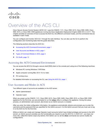
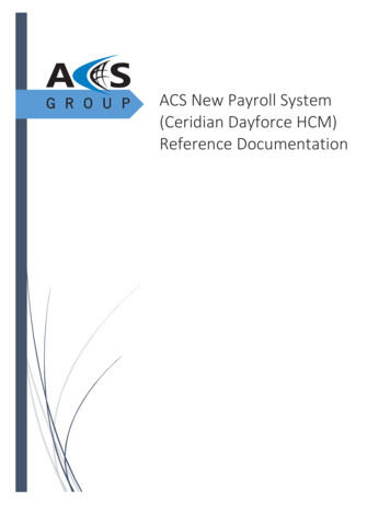
Chapter 1 – IntroductionIntended AudienceThe audience for this manual has: Knowledge of standard electrical wiring practices, electronic components,and electrical schematic symbols. Minimal knowledge of ABB product names and terminology. No experience or training in installing, operating, or servicing theACS 500.Conventions UsedIn This ManualControl Panel DisplayThe following are illustrations and examples of Control Panel keys andControl Panel display formats.The Control Panel display is an LCD readout of drive functions, driveparameter selections, and other drive information. Letters or numbers appearin the display according to which Control Panel keys you press.The operation information, parameters and fault indications are displayed innine languages: English, German, Italian, Spanish, Dutch, French, Danish,Finnish, and Swedish. The language selection is made in Start-up DataParameter A (Language).Figure 1-1 shows control panel display indications.Figure 1-1 Control Panel DisplaysMain NameMain NumberParameter Numberand NameParameter Value1-2Rotation Direction Forward ReverseControl Location[ ] Keypad ControlNo Brackets ExternalRun StatusI RunO StopActive ReferenceR1 Ref 1Mode Indication[ ] Setting ModeNo Brackets Display ModeACS 500 Programming Manual
Chapter 1 – IntroductionControl Panel KeysControl Panel keys are flat, labeled, pushbutton keys that allow you tomonitor drive functions, select drive parameters, and change drive macros andsettings.Table 1-1 illustrates each Control Panel Key as it appears on the Control PanelKeypad. Table 1-1 also shows how the keys are represented in this manual'stext and describes the function of each key.Table 1-1 Control Panel KeysControl PanelKeyText ReferenceFunction[*]Selects the Setting mode and saves the selectedparameter value.[Right Arrow]Steps between levels.Selects between Operating Data, Main, Group,and Parameter levels.and[Left Arrow]In Setting Mode, returns to the Display modewithout changing the Parameter value.[Up Arrow]Steps through choices within a level.In Display mode, selects the next/previous Main,Group, or Parameter.and[Down Arrow]In Setting mode, increases/decreases parametervalue.Related PublicationsACS 500 Programming Manual[Fwd/Rev]Changes the rotation direction in Keypad control(refer to parameter 10.1.3).[Start/Stop]Starts and stops the motor in Keypad control.Resets faults, warnings, and supervisionindications.For related information, refer to the Installation & Start-up Manual.1-3
Chapter 1 – IntroductionThis page intentionally left blank.1-4ACS 500 Programming Manual
Chapter 2 – Overview of ACS 500 ProgrammingThis chapter defines Application macros in terms of parameter settings anddescribes how to use the menu system of parameters to select and modify themacros.Overview of ApplicationMacrosApplication MacrosDefinedApplication macros are pre-programmed parameter sets. You’ll use them tostart the ACS 500 quickly and easily.Application macros minimize the number of different parameters to be setduring start-up. All parameters have factory-set default values. The Factorymacro program is the factory-set default macro.While starting up the ACS 500, you can specify a macro as the base setting fora drive. You can select any one of the following macros from Start-up DataParameter B (Applications): Factory Hand/Auto Ctrl PI-Control Opt. Pack
ACS 500 ABB Drives Programming Manual Including Application Macros ASEA BROWN BOVERI 25.00 U.S. ACS