Transcription
Canopy - VoIPArchitectureApplication NoteCanopy-VoIP-Architecture-AN-enIssue 1June 2006MOTOROLA and the Stylized M Logo are registered in the US Patent & Trademark Office. Allother product or service names are the property of their respective owners. Motorola, Inc. 2006. All rights reserved.
Canopy Platform – VoIP Architecture Application NoteNoticesThe vendor data in this Application Note derive from the Canopy User Guide and variousHotZone provided MetroMesh User Guides. Motorola provides this vendor data forCanopy users information only and does not provide any recommendations.Please refer to the Canopy System User Guide, posted at www.motorola.com/canopy for:Personal safety guidelines in Preventing Overexposure to RF EnergyImportant regulatory and legal noticesTrademarks, Product Names, and Service NamesMOTOROLA, the stylized M Logo and all other trademarks indicated as such herein are trademarks of Motorola, Inc. Reg. U.S. Pat & Tm. Office. Canopy and MOTOMESH aretrademarks of Motorola, Inc. All other product or service names are the property of theirrespective owners. 2006 Motorola, Inc. All rights reserved.http://www.motorola.com/canopyIssue 1, June 2006Page 2
Canopy Platform – VoIP Architecture Application NoteTable of ContentsTable of Figures. 4New in This Issue . 6Using This Canopy – VoIP Architecture Application Note. 6Searching This User Guide. 6Getting Additional Help . 6Canopy – VoIP Architecture Application Note: . 71.0 Abstract:. 72.0 Business Case for VoIP . 72.1 Alternative VoIP Business Opportunities . 92.2 Overview of Canopy Subscriber Analog Telephone CPE .112.3 Subscriber Hard Digital Telephone CPE.152.4 Subscriber’s Computer as a “Soft VoIP Telephone”.162.5 Wireless VoIP Technology for the Subscriber .183.0 FCC Requirements for “Interconnected VoIP Service Providers”.193.1 FCC Order Applicable to “Interconnected” VoIP Providers.204.0 VoIP Signaling Technology.204.1 VoIP Internet-based Signaling.214.2 Soft-Switch and Media Gateway .224.3 Call Admission Control.244.4 VoIP Codecs.245.0 Overview of Canopy for VoIP .255.1 Canopy’s Use of VLAN QoS.275.2 Configuring Canopy Elements for VoIP .275.3 Manually Configuring Canopy for VoIP .285.4 Prizm 2.0 Configuring Canopy for VoIP .336.0 Summary and Conclusion.39Additional Resources .41Appendix A. ITU’s Next Generation Network.41Issue 1, June 2006Page 3
Canopy Platform – VoIP Architecture Application NoteAppendix B. Selected Useful Reference Sites.42Appendix C. Glossary of Terms.42Table of FiguresFigure 1. Generic Canopy-based BWA architecture. . 8Figure 2. VoIP Business Alternatives for Canopy Operators. . 9Figure 3. Diagram of Voice Use Alternatives www.voipreview.org.10Figure 4 Schematic of typical Canopy Subscriber ”data” CPE. .12Figure 5 Schematic of typical Canopy Subscriber ”voice” CPE.13Figure 6 Schematic of CPE with WiFi data capability. .14Figure 7 Three Motorola Analog Terminal Adapters (ATA), one with WiFi. .15Figure 8 Example of two Cisco high end digital VoIP telephones. .16Figure 9 Cell-like softphone by X-Ten used by Vonage.17Figure 10 Examples of Skype and GoogleTalk softphones. .17Figure 11 X-Ten’s softphone on a Microsoft Pocket PC; uses WiFi.19Figure 12 UT Starcom’s F1000G WiFi telephone.19Figure 13 List of VoIP Signaling Protocol Alternatives. .21Figure 14 Schematic of packet flows for “Interconnected Call”. .22Figure 15. Mediant 2000 media gateway by AudioCodes Inc.23Figure 16. Canopy SM mapping of DiffServ codepoints to queue priority. .29Figure 17. Configuration of SM High Priority queue.30Figure 18. Advantage P9 or greater AP QoS Tab .31Figure 19. Canopy AP Sessions tab verifying a SM’s Hi Priority CIR configurations. .32Figure 20 Canopy SM Lite performance restrictions. .33Figure 21. Prizm 2.0 priority settings screen capture. .35Figure 22. Example Configuration Parameter Selection for a Service Plan.36Figure 23. Prizm 2.0 configuration parameters in a Service Plan.36Figure 24. Example Confirm Update window. .36Figure 25. Configured Service Plan window.37Figure 26. Example Apply Configuration window for a Service Plan.38Figure 27. Example Configuration window. .39Figure 28. Example Applying Configuration window for a Service Plan.39Issue 1, June 2006Page 4
Canopy Platform – VoIP Architecture Application NoteFigure 29 Summary illustration of Canopy in VoIP service context.40Issue 1, June 2006Page 5
Canopy Platform – VoIP Architecture Application NoteNew in This IssueThis document is Issue 1 of the Canopy – VoIP Architecture Application Note.This section is a placeholder where changes will be listed in future issues.Using This Canopy – VoIP Architecture Application NoteThis document should be used with following Motorola Canopy documentation: Canopy System User GuideImportant: Visit the Canopy Support Web Site to download the latest Canopy software andCanopy User Guides. g This User GuideTo search this document, look in the Table of Contents for the topic. To find informationbased on any expression used in this document, open the document in an Adobe Reader session andUse the page numbers at the bottom of the screen and in the thumbnails. Thesematch the page numbers in the Table of Contents.Use the Edit Search command (or Ctrl F) to find a word or phrase.1Getting Additional HelpTo get information or assistance as soon as possible for problems that you encounter,use the following sequence of action:1. Search this document, the user manuals that support the modules, and the softwarerelease notes of supported releasesa. in the Table of Contents for the topic. 1b. in the Adobe Reader search capability for keywords that apply.2. Visit the Canopy systems website at http://www.motorola.com/canopy.3. Ask your Canopy products supplier to help.4. Gather information such asthe IP addresses and MAC addresses of any affected Canopy modules.the software releases that operate on these modules.data from the Event Log page of the modules.the configuration of software features on these modules.run the Gather Customer Support Tool within CNUT5. Escalate the problem to Canopy systems Technical Support (or another Tier 3technical support that has been designated for you) as follows. You may eithersend e-mail to technical-support@canopywireless.com.call 1 888 605 2552 (or 1 217 824 9742).For warranty assistance, contact your reseller or distributor for the process.Go to page 39 for Additional Resources1Reader is a registered trademark of Adobe Systems, Incorporated.Issue 1, June 2006Page 6
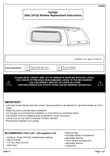
Canopy Platform – VoIP Architecture Application NoteCanopy – VoIP Architecture Application Note:1.0 Abstract:Motorola Canopy is a Broadband Wireless Access (BWA) technology intended for thefixed and nomadic (“portable”) market and employing unlicensed electromagneticspectrum over metropolitan distances. The customer edge of Canopy is an Ethernetcable to a local Internet typically consisting of one or more computer and/or IP routers.Historically, the customer’s network is intended for data.Recently, technology has extended data to include voice; generically termed Voice overIP (VoIP). Unlike data, VoIP is sensitive to end-to-end delay, packet discard in theintermediate network due to congestion, and is a symmetrical flow.This new capability has Canopy operators wondering if and how Canopy-based BWAplays are role in formal or informal VoIP service.As a service to Canopy operators and sales teams, this Application Note describes thecharacteristics of using Canopy BWA in a VoIP architecture and the possible businessopportunities.All non-Motorola vendor examples and their characteristics are derived from publiclyavailable material and are included only to represent possibilities.2.0 Business Case for VoIPIn this section, a short review of the Canopy BWA architecture is provided to set thestage for a VoIP architecture discussion. Figure 1 shows the Canopy operator’s networkwith Canopy Base Stations and customer Subscriber Modules. Note the carrier’snetwork consists of links between packet switches, usually IP routers. In addition, thecarrier’s network is interconnected to one (or more) other Internet Service Providers toattain global Internet connectivity for the carrier’s BWA customers.The Subscriber Module (SM) is produced in several variations, namely the Classic SM,the Advantage SM, and the SM Lite. As the latter is comparatively new it is describedhere.Canopy Lite SMs work with the Canopy Advantage access points and deliver speeds of512 Kbps throughput with 768 Kbps burst and a maximum of 100 Kbps full duplexCommitted Information Rate (CIR). The Canopy Lite SMs offer substantially lower costswith the same high performance, reliability and interference tolerance as all Canopy SMs.The Canopy Lite SM can be software upgraded via floating license keys from the CanopyPrizm element management system to add incremental throughput (to 1, 2, 4 or 7 Mbps)quickly and economically. See Figure 20 for SM Lite’s performance restrictions.Issue 1, June 2006Page 7
Canopy Platform – VoIP Architecture Application NoteFigure 1. Generic Canopy-based BWA architecture.Note that Canopy Lite SM has more than enough throughput capacity to handle a one ortwo VoIP telephone call.Historically, this network architecture is for data, which excludes applications that haveextraordinary performance requirements like end-to-end delay. Now, however, variousVoIP “softphones” and “hardphone” are available for computers that support voice.These softphones either have the look-and-feel of a modern cell telephone or that of amodern instant messaging chat application that additional supports voice. Hardphoneshave the look-and-feel of ordinary digital telephones.This level of VoIP-based telephony is transparent from the underlying internetinfrastructure technology. The Canopy-based BWA and the wired internet infrastructureare oblivious to any peer-to-peer VoIP packet flows. The one exception to thistransparency is any Network Address Translator (NAT) between the voice endpoints, forexample, such as can be configured in a Canopy Subscriber Module or other customerCPE router.NAT is a problem because peer-to-peer communication, like voice, requires applicationsignaling end-to-end. This means the applications embed their own IP address inapplication layer packets, and expect to be communicating directly with the far end. NAT,by definition, breaks this by hiding the actual IP addresses from each other.This “NAT problem” leads to solutions like STUN (Simple Transversal of UDP overNATs), in which both ends of the potential peer-to-peer communication must first register.This enables the endpoints to know the intermediate public IP addresses of the NAT(s)such that proper exchange of signal can take place. Another solution is to make thevoice application into a web application which, because it is widely “open”, also defeatsNATs and firewalls.The important point is that Canopy-based customers may be employing voiceapplications even now without the Canopy operator even knowing or doing anything.Issue 1, June 2006Page 8
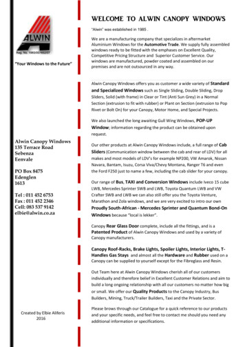
Canopy Platform – VoIP Architecture Application NoteHowever, at this level of VoIP, the Canopy operator is not functioning as a VoIP ServiceProvider nor billing for voice services. This paper discusses the VoIP businessopportunity alternatives possible for a Canopy BWA operator.2.1 Alternative VoIP Business OpportunitiesRather than the transparent VoIP use of a Canopy BWA system the Canopy operator hasseveral options for providing value added revenue enhancing VoIP services.A set of VoIP service business alternatives are listed in Figure 2 below. Note Item 1 isthe “do nothing” scenario described in Section 2.0 above.The first VoIP business alternative is for a Canopy operator to offer a Service LevelAgreement (SLA), differentially priced, stipulating Canopy’s QoS capabilities. Theseservices levels are often referred to in the “Olympic Model” of Gold, Silver, and Bronze.Prizm 2.0 offers the capability to create service plans to offer multiple service levels.The next VoIP business alternative is to provide customer VoIP capability to thecustomer’s usual analog telephones. The box is generically termed an Analog TerminalAdaptor (ATA). Motorola and many of vendors make ATA devices intended for theresidential SOHO consumer. Here the Canopy BWA operator either sells the ATA orcharges a recurring monthly fee to the customer.1.Offer nothing but BWA; no explicit VoIP service–2.Allow third party-based VoIP service or peer-to-peer voice betransported transparently; no VoIP revenueOffer stipulated QoS and CIR BWA service–3.SLA fee but without reference to “voice”Offer to provide Analog Terminal Device only––4.Or similar CPE deviceSLA fee but not be a VoIP Service providerOffer and become an “interconnected” VoIP Serviceprovider; fee: bill subscriber per minute–That is interconnected to the PSTN (Public Switched TelephoneNetwork); provide E911Figure 2. VoIP Business Alternatives for Canopy Operators.The last Canopy operator VoIP business alternative is to become a full-fledged VoIPService Provider. In this case the Canopy operator literally becomes a telephonyprovider meaning the providing of “hard” or “soft” VoIP telephone sets, providing bothinbound and outbound VoIP calls to regular Public Switched Telephone Network-based(PSTN) subscribers, provide Enhanced 911 (E911) and operator services, and of courseprovide itemized bills based on a per-minute subscription plan.The latter alternative is clearly a huge step so the business ramifications are the focus ofthis paper.The various business opportunities from a user/customer perspective are shown again inFigure 3. This diagram shows a generic Broadband Modem connecting to a genericIssue 1, June 2006Page 9
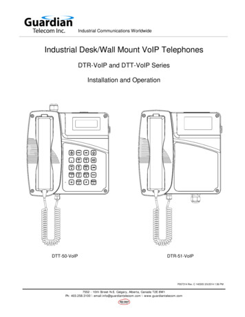
Canopy Platform – VoIP Architecture Application Noteinternet icon; of course in the Canopy context the Broadband Modem is the CanopySubscribe Module (SM) and access is wireless.Figure 3. Diagram of Voice Use Alternatives www.voipreview.org.From the top, the PC-to-PC is the “do nothing” alternative, with VoIP softphones oncomputers. This is most likely already happening over a Canopy operator’s network.The second case shown, PC-to-Phone, requires that the Canopy customer hasadditionally subscribed to a so-called inbound/outbound service. This requires asubscription fee, but of course, the Canopy operator is not participating in this scenario.Issue 1, June 2006Page 10
Canopy Platform – VoIP Architecture Application NoteThe third case, Phone-to-Phone (PC compatible adapter), requires the special ATAdevice mentioned above. Note, in context, that the ATA is directly connected to theCanopy SM, with both computers and wired analog telephone sets also attaching to theATA. Because the call could originate or terminate in the PSTN a VoIP Service Providerwith an inbound/outbound service is also required; this may or may be the Canopyoperator.The final (bottom) schematic shows Phone-to-Phone (Router) customer networking.Here the Canopy SM is connected to a home IP router, possibly with WiFi capability aswell. The latter device is then connected to computers and an Analog Terminal Adaptor(ATA), with ordinary telephones attached to the ATA. This is the case in which theCanopy operator is a full-blown telephony service provider.There are many VoIP telephony service providers, ranging from all the usual telephonecompan
Canopy Platform – VoIP Architecture Application Note Issue 1, June 2006 Page 7 Canopy – VoIP Architecture Application Note: 1.0 Abstract: Motorola Canopy is a Br