Transcription
Practical Design to Eurocode 223/11/16Practical Design to Eurocode 2The webinar will start at 12.30Course OutlineLecture DateLecture 10: FoundationsSpeakerTitle121 Sep Charles Goodchild Introduction, Background and Codes2328 Sep Charles Goodchild EC2 Background, Materials, Coverand effective spans5 Oct Paul GregoryBending and Shear in Beams412 Oct Charles Goodchild Analysis519 Oct Paul Gregory626 Oct Charles Goodchild Deflection and Crack Control72 NovPaul GregoryDetailing89 NovJenny BurridgeColumns916 Nov Jenny BurridgeFire1023 Nov Jenny BurridgeFoundationsSlabs and Flat Slabs1
Practical Design to Eurocode 223/11/16FoundationsLecture 1025th November 2015Model AnswersLecture 9 Exercise:Fire resistance of ColumnLecture 10: Foundations2
Practical Design to Eurocode 223/11/16Fire resistance of columnUsing Equation 5.7, work out the fire resistance of a 250x 750 column with an axial capacity of 3750kN and anaxial load in cold conditions of 3500kN. The column is onthe ground floor of a three storey building and the lengthis 4.5m. The cover is 30mm, main bars are 20mm andthe links are 10mm diameter.Design Exercise Answers 120( 120 ).μfi 0.7 x 3500/3750 0.65Rηfi 83(1 - 0.65) 28.8a 30 10 10 50mmRa 1.6(50 - 30) 32l0,fi 0.5 x 4.5 2.25mRl 9.6(5 - 2.25) 26.4b’ 1.2 x 250 300mmRb 0.09 x 300 27n 4Rn 12R 120((Rηfi Ra Rl Rb Rn)/120)1.8 131 minutesLecture 10: Foundations3
Practical Design to Eurocode 223/11/16FoundationsOutline – Week 10, FoundationsWe will look at the following topics: Eurocode 7: Geotechnical design –Partial factors, spreadfoundations. Pad foundation – Worked example & workshop Retaining walls PilesLecture 10: Foundations4
Practical Design to Eurocode 223/11/16Eurocode 76(p43 et seq)Eurocode 7 has two parts:Part 1: General RulesPlus NAPart 2: Ground Investigation and testingPlus NAEurocode 7How to 6. FoundationsThe essential features of EC7, Pt 1 relatingto foundation design are discussed.Note:This publication covers only the design ofsimple foundations, which are a small partof EC7.It should not be relied on for generalguidance on EC7.Lecture 10: Foundations5
Practical Design to Eurocode 223/11/16Limit StatesThe following ultimate limit states apply to foundationdesign:EQU: Loss of equilibrium of the structureSTR: Internal failure or excessive deformation of thestructure or structural memberGEO: Failure due to excessive deformation of the groundUPL: Loss of equilibrium due to uplift by water pressureHYD: Failure caused by hydraulic gradientsCategories of StructuresCategory DescriptionLecture 10: FoundationsRisk of geoExamples fromtechnical failure EC71Small and relativelysimple structuresNegligibleNone given2Conventional types ofstructure – no difficultgroundNo exceptionalriskSpreadfoundations3All other structuresAbnormal risksLarge or unusualstructures6
Practical Design to Eurocode 223/11/16EC7 – ULS DesignEC7 provides for three Design ApproachesUK National Annex - Use Design Approach 1 – DA1For DA1 (except piles and anchorage design) there are twosets of combinations to use for the STR and GEO limitstates.Combination 1 – generally governs structural resistanceCombination 2 – generally governs sizing of foundationsSTR/GEO ULS –Actions partial factorsPermanent Accompanying variableactionsExp 6.101.35Gk1.0Gk1.5QkExp 6.10a1.35Gk1.0GkExp �0,iQkMainOthersCombination 11.5ψ0,iQk1.5ψ0,1Qk1.5ψ0,iQkCombination 2Exp 6.10Notes:If the variation in permanent action is significant, use Gk,j,sup and Gk,j,infIf the action is favourable, γQ,i 0 and the variable actions should be ignoredLecture 10: Foundations7
Practical Design to Eurocode 223/11/16Factors for EQU, UPL and HYDLimitstatePermanent eEQU1.10.91.50UPL1.10.91.50HYD1.350.91.50Partial factors –ParameterVariable Actionsmaterial propertiesSymbolCombination Combination12EQUAngle of shearingresistanceγφ1.01.251.1Effective cohesionγc’1.01.251.1Undrained shearstrengthγcu1.01.41.2Unconfined strengthγqu1.01.41.2Bulk densityγγ1.01.01.0Lecture 10: Foundations8
Practical Design to Eurocode 223/11/16Geotechnical ReportThe Geotechnical Report should: be produced for each project (if even just a single sheet) contain details of: the site, interpretation of ground investigation report, geotechnical recommendations, adviceFoundation design recommendations should state: bearing resistances, characteristic values of soil parameters and whether values are SLS or ULS , Combination 1 orCombination 2 valuesSpread FoundationsEC7 Section 6Three methods for design: Direct method – check all limit states: Load and partial factor combinations (as before) qult c’Ncscdcicgcbc q’Nqsqdqiqgqbq ��––Lecture 10: Foundationsc cohesionq overburdenγ body-weightNi bearing capacity factorssi shape factorsdi depth factorsii inclination factorsgi ground inclination factorsbi base inclination factors“We just bung it in aspreadsheet”Settlement often criticalSee Decoding Eurocode 7 by ABond & A Harris, Taylor & Francis9
Practical Design to Eurocode 223/11/16Spread FoundationsEC7 Section 6Three methods for design: Direct method – check all limit states Indirect method – experience and testingused to determine SLS parameters thatalso satisfy ULS Prescriptive methods – use presumedbearing resistance (BS8004 quoted in NA).Used in subsequent slides).Spread FoundationsDesign procedures in:Lecture 10: Foundations10
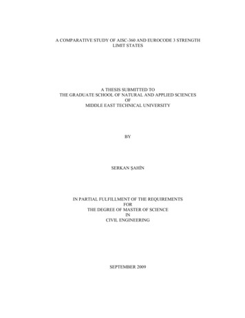
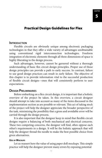
Practical Design to Eurocode 223/11/16Fig 6/1 (p46)Procedure for depth ofspread foundationsPressure distributionsSLS pressuredistributionsULS pressuredistributionLecture 10: Foundations11
Practical Design to Eurocode 223/11/16Load casesEQU : 0.9 Gk 1.5 Qk (assuming variable action isdestabilising e.g. wind, andpermanent action is stabilizing)STR : 1.35 Gk 1.5 Qk (Using (6.10). Worse case of Exp(6.10a) or (6.10b) could be used)Plain Concrete Strip Footings &Pad Foundations:Cl. 12.9.3, Exp (12.13)0,85 hF (3σgd/fctd,pl)ahFwhere:σgd is the design value of the ground pressure as a simplification hf/a 2 may be usedaabFLecture 10: Foundations12
Practical Design to Eurocode 223/11/16Plain Concrete Strip Footings &Pad Foundationsallowablepressure C30/37hF /ahF /ahF/ahF 0.951.101.23e.g. cavity wall 300 wide carrying 80 kN/m onto 100 kN/m2ground:bf 800 mma 250 mmhf say assuming C20/25 concrete0.85 x 250 213 say 225 mm0.520.740.901.041.17hFaabFReinforced Concrete Bases Check critical bending moments at column faces Check beam shear and punching shearFor punching shear theground reaction withinthe perimeter may bededucted from thecolumn loadLecture 10: Foundations13
Practical Design to Eurocode 223/11/16Pad foundationWorked exampleWorked ExampleDesign a square pad footing for a 350 350 mm columncarrying Gk 600 kN and Qk 505 kN. The presumedallowable bearing pressure of the non-aggressive soil is200 kN/m2.Answer:Category 2. So using prescriptive methods:Base area: (600 505)/200 5.525m2 2.4 x 2.4 base x 0.5m (say) deep.Lecture 10: Foundations14
Practical Design to Eurocode 223/11/16Worked ExampleLoading 1.35 x 600 1.5 x 505 1567.5 kNULS bearing pressure 1567.5/2.42 272 kN/m2Critical section at face of columnMEd 272 x 2.4 x 1.0252 / 2 343 kNmd 500 – 50 – 16 434 mmKUse C30/37 concrete 343 x106/(2400 x 4342 x30) 0.025Worked Example z 0.95d 0.95 x 434 412mm As MEd/fydz 343 x 106 / (435 x 412) 1914mm2 Provide 10H16 @ 250 c/c b.w (2010 mm2) (804 mm2/m)Beam shear:Check critical section d away from column faceVEd 272 x (1.025 – 0.434) 161kN/mvEd 161 / 434 0.37MPaρ 2010/ (434 x 2400) 0.0019 0.19%vRd,c (from table) 0.42MPa6/Table 6 (p47)Concise Table 15.6 beam shear ok.Lecture 10: Foundations15
Practical Design to Eurocode 223/11/16Worked ExamplePunching shear:Basic control perimeter at 2d from face of columnvEd βVEd / uid vRd,cβ 1, ui (350 x 4 434 x 2 x 2 x π) 6854mmVEd load minus net upward force within the area of thecontrol perimeter) 1567.5 – 272 x (0.352 π x .8682 .868 x .35 x 4) 560kNvEd 0.188 MPa; vRd,c 0.42 (as before) okRetaining WallsChapter 9Lecture 10: Foundations16
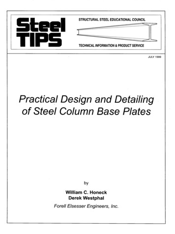
Practical Design to Eurocode 223/11/16Ultimate Limit Statesfor the design ofretaining wallsCalculation Model ARankine theoryModel applies if bh ha tan (45 - ϕ’d/2)Lecture 10: Foundations17
Practical Design to Eurocode 223/11/16Calculation Model BInclined ‘ virtual’ plane theoryModel applies to walls of all shapes and sizesGeneral expressionsGeneralWs b sHγ k,ch tb H bh tanβWb tbBγ k,c b tanβ Wf bh H h γk,f2 bLf bt bs h2Ω βbh B b s b tbL s bt s2BLb 2Lecture 10: FoundationsModel AModel BLvp B18
Practical Design to Eurocode 223/11/169 (Figure 4)Overall designprocedureInitial sizingbs tb h/10 to h/15B 0.5h to 0.7hbt B/4 to B/3Lecture 10: Foundations19
Practical Design to Eurocode 223/11/169 (Figure 4)Overall designprocedure9 (Figure 6)Figure 6 for overalldesign procedureLecture 10: Foundations20
Practical Design to Eurocode 223/11/16Soil DensitiesEx Concrete BasementsDesign value of effective angleof shearing resistance, φ’dtan φ’d tan (φ’k/γφ)whereφ’k φ’max for granular soils and φ’ for clay soils,φ’max and φ’ are as defined as followsγφ 1.0 or 1.25 dependent on theCombination being considered.Ex Concrete BasementsLecture 10: Foundations21
Practical Design to Eurocode 223/11/16Angle of shearing resistanceGranular SoilsEstimated peak effective angle of shearing resistance,φ’max 30 A B CEstimated critical state angle of shearing resistance,φ’crit 30 A B, which is the upper limiting value.Ex Concrete BasementsClay soilsLong term Granular SoilsEx Concrete BasementsLecture 10: Foundations22
Practical Design to Eurocode 223/11/16Calcs –Material properties & earth pressures9 (Panel 2)9 Panel 2(p71)2’9 (Figure 4)Overall designprocedureLecture 10: Foundations23
Practical Design to Eurocode 223/11/169 (Figure 7)Design againstsliding(Figure 7)Sliding Resistance9 (Panel 3)Lecture 10: Foundations24
Practical Design to Eurocode 223/11/169 (Figure 4)Overall designprocedureDesign against Toppling9 (Figure 9)Lecture 10: Foundations25
Practical Design to Eurocode 223/11/169 (Figure 4)Overall designprocedureDesign against bearing failure9 (Figure 10)Lecture 10: Foundations26
Practical Design to Eurocode 223/11/16Expressions for bearing resistance9 (Panel 4,Figure 11)9 (Figure 4)Overall designprocedureLecture 10: Foundations27
Practical Design to Eurocode 223/11/16Structural design9 (Figure 13)Remember: Load and PartialFactor CombinationsParameterSymbolComb. 1Comb. 2γG,unfav1.351.0γG,fav1.001.00γQ1.501.30Angle of shearing resistanceγφ1.01.25Effective cohesionγc’1.01.25Undrained shear strengthγcu1.01.4Unconfined strengthγqu1.01.4Bulk densityγγ1.01.0ActionsPermanent action : unfavourablePermanent action: favourableVariable actionSoil PropertiesLecture 10: Foundations28
Practical Design to Eurocode 223/11/16PilesFlexural and axial resistanceof piles‘Uncertainties related to the cross-section of cast in place piles andconcreting procedures shall be allowed for in design’‘In the absence of other provisions’, the design diameter of cast in placepiles without permanent casing is less than the nominal diameter Dnom: Dd Dnom – 20 mm for Dnom 400 mm Dd 0.95 Dnom for 400 Dnom 1000 mm Dd Dnom – 50 mm for Dnom 1000 mmICE Specification for piling and embedded retaining walls (ICE SPERW)B1.10.2 states ‘The dimensions of a constructed pile or wall element shallnot be less than the specified dimensions’. A tolerance of 5% on augerdiameter, casing diameter, and grab length and width is permissible.Lecture 10: Foundations29
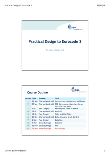
Practical Design to Eurocode 223/11/16Flexural and axial resistanceof piles The partial factor for concrete, γc, should be multiplied by afactor, kf, for calculation of design resistance of cast in placepiles without permanent casing. The UK value of kf 1.1, therefore γc,pile 1.65 “If the width of the compression zone decreases in the directionof the extreme compression fibre, the value η fcd should bereduced by 10%”Bored pilesReinforcement should be detailed for free flow ofconcrete.Minimum diameter of long. reinforcement 16mmMinimum number of longitudinal bars 6[BUT – BS EN 1536 Execution of special geotechnical work Bored Pilessays 12 mm and 4 bars!]Minimum areas:Pile crosssection: AcAc 0.5 m20.5m2 Ac 1.0Ac 1.0 m2Lecture 10: Foundationsm2Min area of long.rebar, As,bpminPilediameters 0.5% Ac 800 mm 2500mm2 0.25% Ac 1130 mm30
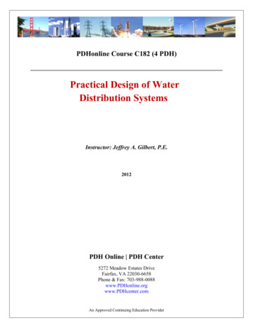
Practical Design to Eurocode 223/11/16Minimum area of reinforcement,As,bpmin (mm2)Minimum 00002004006008001000120014001600Pile diameter, mmWorkshopDesign a pad foundation for a 300mm square columntakingGk 600kN, Qk 350kN.Permissible bearing stress 225kPa.Concrete for base C30/37.Work out size of base, tension reinforcement and any shear reinforcement.Lecture 10: Foundations31
Practical Design to Eurocode 223/11/16Workshop ProblemCategory 2, using prescriptive methodsBase size: (Gk Qk)/bearing stress m2 x base x mm deep (choose size of pad)Use C 30/37 (concrete)Loading γg x Gk γq x Qk kNULS bearing pressure / 2 kN/m2Critical section at face of columnMEd x x 2 / 2 kNmd – cover – assumed ø mmK M/bd2fck Workshop Problem z d As MEd/fydz x mmTable 15.5mm2 Provide H @ c/c ( mm2)Check minimum steel100As,pr
Practical Design to Eurocode 2 23/11/16 Lecture 10: Foundations 14 Pad foundation Worked example Worked Example Design a square pad footing for a 350 350 mm column carrying Gk 600 kNand Qk 505 kN.The presumed allowable bearing pressure of the non-aggressive soil is 200 kN/m 2. Answer: Category 2. So using prescriptive methods: