Transcription
DIAGNOSTIC SERVICE MANUALAMERICANA & AMERICANA PLUSRM 2351, RM 2354, RM 2451, RM 2454RM 2551, RM 2554, RM 2652, RM 2662RM 2663, RM2852, RM2862 & NDR1062USASERVICE OFFICEDometic Corporation2320 Industrial ParkwayElkhart, IN 46516574-294-2511CANADADometic Distribution46 Zatonski Unit 3Brantford, OntarioCANADA N3T 5L8519-720-9578For Service CenterAssistance Call:800-544-4881Form No. 3311143.000 02/07 2007 Dometic CorporationLaGrange, IN 46761
Safety InstructionsForewordThis service manual is the result of the dedication of The Dometic Corporation Technical staffand its engineers in giving service people thenecessary instruction for making accurate analyses of certain conditions. Provided is a diagnostic chart leading a qualified mechanic into theservice manual pages to locate and solve symptoms which may occur. Dometic has continuedits commitment in providing service people withthis, the most up-to-date information about servicing Dometic RV accessories.This manual has safety information and instructions to help users eliminate or reduce the riskof accidents and injuries.Recognize Safety InformationThis is the safety-alert symbol. When you see thissymbol in this manual, be alert to the potentialfor personal injury.Follow recommended precautions and safe operating instructions.Understand Signal WordsA signal word , WARNING OR CAUTION is usedwith the safety-alert symbol. They give the levelof risk for potential injury.Indicates a potentially hazardous situation which, if not avoided, could resultin death or serious injury.Indicates a potentially hazardous situation which, if not avoided may result inminor or moderate injury.When used without the safetyalert symbol indicates, a potentially hazardoussituation which, if not avoided may result in property damage.Read and follow all safety information and instructions.
CONTENTSPAGE NO.DIAGNOSTIC FLOW CHART. 4SECTION 1OPERATIONRefrigerator Operation .6SECTION 2AC VOLTAGEAC Voltage Requirements.9SECTION 3AC COMPONENTSHeating Element .10SECTION 4DC VOLTAGEDC Voltage Requirements .10SECTION 5DC .135.14DC heating Element .11Thermistor .11Solenoid Valve.11Igniter .11High Voltage Cable .12Electrode.12DC Relay.12Upper Circuit Board .13Lower Circuit Board .13Door Switch .18Climate Control Heater & Switch .18Low Ambient Switch .18Fuses.18Thermofuse.18SECTION 6LP GASLP Gas Requirements .19SECTION 7LP GAS COMPONENTS7.17.27.37.4Manual Gas Shut-Off Valve .19Orifice .19Thermocouple .20Burner .20
CONTENTSPAGE NO.SECTION 77.5 Flue Baffle.207.6 Flue Cap .207.7 Flue Tube .20SECTION 8COOLING ion.21Air Leaks.23Interior Liner Seal to Frame.23Door Position.24Ambient Temperature.24Cooling Unit.25Food Storage.26High Humidity.26SECTION 9WIRING9.1 Internal Wiring.269.2 External Wiring.269.3 Wiring Schematics.26SECTION 10ICE MAKER10.1 Operation.2610.2 Mold Heater.2710.3 Ice Ejector.2710.4 Mold Thermostat.2710.5 Shut Off Arm.2710.6 Mold Switches.2710.7 Timing Motor.2810.8 Water Valve.2810.9 Ice Maker Replacement.2810.10 Water Fill Adjustment.2810.11 Water Supply.2910.12 Wiring Schematics.29
This program will address the most common system problems associated with the RM2351, RM2354, RM2451, RM2454,RM2551, RM2554, RM2652 ,RM2662,RM2663,RM2852and RM2862 refrigerators supplied by The Dometic Corporation.Our intent is to provide you with a guideline of checks to make, should you encounter one of the following symptoms.SYMPTOMCAUSESECTION & PAGE1.No operation - no panel lightsOperationDC VoltsFuseWiringUpper Circuit BoardLower Circuit Board1, page 064, page 105, page 189, page 265, page 135, page 132.No operation - has panel lightsOperationDC VoltsThermistorWiringLower Circuit Board1, page 064, page 105, page 119, page 265, page 143.No AC operation - operates on gas modeOperationAC VoltsFuseHeating ElementWiringLower Circuit Board1, page 072, page 095, page 193, page 119, page 245, page 134.No Gas operation - operates on AC modeOperationLP GasManual Gas ValveIgniterHigh Voltage CableElectrodeSolenoidWiringLower Circuit Board1, page 066, page 197, page 195, page 115, page 125, page 125, page 119, page 245, page 135.Insufficient cooling on all modes.VentilationLevelingAmbient TemperatureAir LeaksThermistorCooling Unit8, page 218, page 218, page 248, page 235, page 118, page 256.Insufficient cooling on AC - cools properlyon gas mode.AC VoltsHeating ElementLower Circuit Board2, page 093, page 105, page 137.Insufficient cooling on Gas - cools properlyon AC mode.LP GasOrificeFlue BaffleFlue TubeBurnerLower Circuit Board6, page 197, page 197, page 207, page 207, page 205, page 138.Freezes.OperationThermistorLower Circuit Board1, page 065, page 125, page 14
SYMPTOMCAUSESECTION & PAGE9.DC VoltsWiringLP GasManual Gas ValveSolenoidOrificeBurnerThermocoupleLower Circuit Board4, page 109, page 266, page 197, page 195. page 117. page 197. page 207. page 205. page 1310. Interior light on when door is closedWiringLow Ambient SwitchDoor SwitchDoor Position9. page 265. page 185. page 188. page 2411. Rapid formation of frostFood StorageInterior Liner to FrameHigh HumidityAir Leaks8. page 268. page 238. page 268. page 2312.Interior Liner to FrameHigh HumidityAir LeaksClimate Control Heater8. page 238. page 268. page 235. page 18Check light onWater on frame
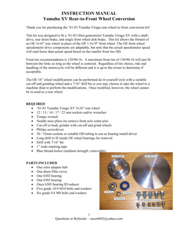
SECTION 1REFRIGERATOR OPERATIONDISPLAY PANEL RM2351, RM2451, RM2551, RM2652, RM2852AUTO TEMPERATURE CONTROLRefrigerator Control PanelRM2652 & RM2852RM2662 & RM2862AMERICANA 2-WAY MODEL1. Main Power Button ON/OFF2. AUTO/GAS Mode Selector ButtonRM2451 & RM2551A. AUTO Mode indicator lampB. CHECK indicator lamp (Gas ModeOnly)C. Climate control switch only onRM2652 & RM2862Travel Latch RM2351
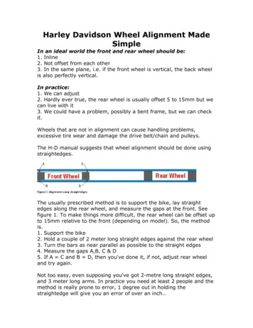
DISPLAY PANEL RM2354, RM2454, RM2554 RM2663 3-wayDISPLAY PANEL RM2662, RM2862 2-WAYRefrigerator Control Panels3-WAY2-WAY3-WAYRM2454 & RM2554Travel Latch RM23541. Main Power Button ON/OFF2. DC Mode Selector Button3. AUTO/GAS Mode Selector Button4. Temperature Selector ButtonA. DC Mode Indicator LampB. AC Mode Indicator LampC. GAS Mode Indicator LampD. AUTO Mode Indicator LampE. CHECK Indicator Lamp(Gas Operation Only)F. Temperature Indicator Lamps2-WAY1. Main Power Button ON/OFF2. AUTO/GAS Mode Selector Button3. Temperature Selector ButtonB. AC Mode Indicator LampC. GAS Mode Indicator LampD. AUTO Mode Indicator LampE. CHECK Indicator Lamp( GAS Mode Only)F. Temperature Indicator Lamps
OPERATION INSTRUCTIONSOPERATIONAuto ThermostatA. A continuous 12 volt DC supply must be available forthe electronic control to function.B. Press the main power ON/OFF button (1) tothe DOWN position.C. In AUTO mode, the AUTO lamp A will be illuminated.The control system will automatically select betweenAC and GAS operation with AC having priority. Thetemperature is controlled by a factory preset temperature setting.D. In GAS mode operation, no lamps will be illuminatedand the temperature is controlled by a factory presettemperature setting.IMPORTANCE OF LEVELING AREFRIGERATORIn an absorption refrigerator system, ammonia is liquefiedin the finned condenser coil at the top rear of the refrigerator. The liquid ammonia then flows into the evaporator(inside the freezer section) and is exposed to a circulating flow of hydrogen gas, which causes the ammonia toevaporate, creating a cold condition in the freezer. Whenstarting this refrigerator for the very first time, the coolingcycle may require up to four hours of running time before the cooling unit is fully operational. The tubing in theevaporator section is specifically sloped to provide a continuous movement of liquid ammonia, flowing downwardby gravity through this section. If the refrigerator is operated when it is not level and the vehicle is not moving, liquid ammonia will accumulate in sections of the evaporatortubing. This will slow the circulation of hydrogen and ammonia gas, or in severe cases, completely block it, resulting in a loss of cooling. Any time the vehicle is parked forseveral hours with the refrigerator operating, the vehicleshould be leveled to prevent this loss of cooling. The vehicle needs to be leveled only so it is comfortable to live in(no noticeable sloping of floor or walls). When the vehicleis moving, the leveling is not critical, as the rolling andpitching movement of the vehicle will pass to either sideof level, keeping the liquid ammonia from accumulating inthe evaporator tubing.OPERATIONAdjustable ThermostatA. A continuous 12 volt DC supply must be available forthe electronic control to function.B. Press the main power ON/OFF button (1) to the DOWNposition.C. In AUTO mode, the AUTO lamp D will be illuminated.The control system will automatically select betweenAC and GAS operation with AC having priority. Temperature is selected by the user.D. In GAS mode operation, the GAS lamp C will be illuminated and only operate on LP only. Temperature isselected by user.E. In DC mode, the DC lamp A will be illuminated and theunit will only operate on DC until DC volts drops below9.6 VDC.OPERATIONBefore starting the refrigerator, check that all the manualgas valves are in the ON position. DO NOT forget themanual shutoff valve on the rear of the refrigerator. Thisrefrigerator is equipped with a control system which canbe set to automatically select either 120 volt AC or LP gasoperation (AUTO mode), or if desired LP gas only (GASmode) or DC volts (DC Heater) where applicable.Auto ThermostatIn both AUTO mode and GAS mode operation, the temperature is controlled by a factory preset temperature setting. The refrigerator controls will work down to 9.6 voltDC.Auto ModePress the AUTO/GAS button 2 (Auto Thermostat) or button 3 (Adjustable Thermostat) to the DOWN position. TheAUTO mode indicator lamp (A auto or D adjustable thermostat) will illuminate. If 120 volts AC is available, thecontrol system will select AC operation. If 120 volts AC isnot available, the control system will automatically switchto GAS operation. Within 45 seconds the burner shouldbe ignited and operating normally. If the CHECK indicatorlamp (B auto or E adjustable thermostat) illuminates, thecontrol has failed to ignite the burner on GAS. To resetwhen the CHECK indicator lamp, press the main powerON/OFF button (1) to the OFF then ON position. Systems with the new lower control board are a three (3) trysystem on gas. On the initial refrigerator start-up on gas(120 volts AC is not available), it may take longer than 45seconds to allow air to be purged from the gas line. If therefrigerator has not been used for a long time or the LPtanks have just been refilled, air may be trapped in thesupply lines. To purge the air from the lines may requireresetting the main power ON/OFF button (1) three or fourtimes. If repeated attempts fail to start the LP gas operation, check to make sure that the LP gas supply tanks arenot empty and all manual shutoff valves in the lines areopen.Most LP gas appliances used in recreational vehicles are vented to the outside of thevehicle. When parked close to a gasolinepump, it is possible that the gasoline fumescould enter this type of appliance and ignitefrom the burner flame, CAUSING A FIRE ORAN EXPLOSION.FOR YOUR SAFETY, when refueling, shutoff all LP gas appliances which are ventedto the outside.
a period of approximately 45 seconds with two minutes (purge) interval after each trial. If unsuccessful, theCHECK indicator lamp (B) will illuminate. To restart GASoperation, press the main power ON/OFF button (1) tothe OFF and then ON position. The control system willattempt a new ignition sequence. If the refrigerator hasnot been used for a long time or the LP tanks have justbeen refilled, air may be trapped in the supply lines. Topurge the air from the lines may require resetting the mainpower ON/OFF button (1) three or four times. If repeatedattempts fail to start the LP gas operation, check to makesure that the LP gas supply tanks are not empty and allmanual shutoff valves in the lines are turned on.Note: Do not continue to reset GAS operation if theCHECK indicator lamp continues to be illuminated afterseveral tries.GAS ModeMove the AUTO/GAS button 2 (Auto Thermostat) or button3 (Adjustable Thermostat) to the UP position. The AUTOmode indicator lamp (A) will go off. Within 45 seconds theburner should be ignited and operating normally.DC Mode 3 Way Units OnlyPress the DC mode indicator button (2) to the DOWNposition. (Lamp [A] will light). Press the TEMPERATURESELECTOR button (4) until the lamp (F) at the desiredposition is illuminated. The refrigerator will continue to operate in the DC mode until switch (2) is moved to the UPposition or control voltage falls below 9.6 VDC. The DCmode overrides all the other operating modes. Discharging of the battery will occur if the vehicle engine is notrunning.Note: The DC mode is a holding mode not a full cooling mode. DC should be used once the unit is cooleddown and constant supply of DC available (drivingdown the road).DC Mode 3 Way Units OnlyPress the DC mode indicator button (2) to the DOWNposition. (Lamp [A] will light). Press the TEMPERATURESELECTOR button (4) until the lamp (F) at the desiredposition is illuminated. The refrigerator will continue to operate in the DC mode until switch (2) is moved to the UPposition or control voltage falls below 9.6 VDC.The DC mode overrides all the other operating modes.Discharging of the battery will occur if the vehicle engineis not running.Note: The DC mode is a holding mode not a full cooling mode. DC should be used once the unit is cooleddown and constant supply of DC available (drivingdown the road).To Shut Off The RefrigeratorThe refrigerator may be shut off while in any mode ofoperation by pressing the main power ON/OFF button tothe UP (OFF) position. This shuts off all DC power to thecontrol system.Description Of Operating ModesAuto ModeTo Shut Off The RefrigeratorWhen operating in the AUTO mode, the AUTO mode indicator lamp (A) will illuminate. The control system willautomatically select between AC and GAS operation withAC having priority over GAS. If the control system is operating with AC energy and it then becomes unavailable,the system will automatically switch to GAS. As soon asAC becomes available again the control will switch backto AC operation. Gas operation (120 volts AC is not available). The control system will activate the ignition system and will make three attempts to light the burner fora period of approximately 45 seconds with two minutesrest (purge) interval. If unsuccessful, the CHECK indicator lamp (B) will illuminate. To restart an ignition attemptwith the CHECK lamp illuminated or to clear (turn off) theCHECK lamp, press the main power ON/OFF button tothe OFF position and wait a few seconds, then return tothe ON position. The control system will attempt a new ignition sequence. If 120 volts AC becomes available whilethe CHECK indicator lamp is on, the CHECK lamp will notturn off until the main power ON/OFF button is pressedto the OFF then ON position but the unit will operate onAC.The refrigerator may be shut off while in any mode ofoperation by pressing the main power ON/OFF button tothe UP (OFF) position. This shuts off all DC power to thecontrol system.Limp ModeThis control system contains a feature where it will continue to operate the cooling system in event of a failure ofa major operating component. If the control cannot readthe temperature sensor and control to the preset temperature, then the control will run the cooling unit continuously at the energy source available. The refrigerator willcontinue to operate in this mode indefinitely or until a newsensor is installed and the system is reset.SECTION 2 AC VOLTAGEAC VOLTAGE REQUIREMENTSThis is an energized circuit. Shock can occurif not tested properly. Testing is to be doneby a qualified ser
Dometic Corporation 2320 Industrial Parkway Elkhart, IN 46516 574-294-2511 CANADA Dometic Distribution 46 Zatonski Unit 3 Brantford, Ontario CANADA N3T 5L8 519-720-9578 For Service Center Assistance Call: 800-544-4881 Form No. 3311143.000 02/07