Transcription
AutoCAD ElectricalSymbol LibrariesAutoCAD Electrical 2005Symbol file names should conform to the AutoCAD Library Symbol NamingConventionsElectrical naming convention. Though not mandatory,you are encouraged to follow the convention in order to Using Multiple Symbol Libraries Substituting Symbols in theLibrarytake full advantage of the AutoCAD Electrical features.The following pages describe the naming conventionsthat should be followed when you create or modifylibrary symbols. Schematic Library Symbols
Library Symbol Naming ConventionsThe default symbol subdirectory, jic1, and a companion 0.125 uniform textheight library, jic125, each contain many hundreds of component symbolsin standard AutoCAD ".dwg" file format. These are referenced by AutoCADElectrical and its icon menuing system and are inserted as standard AutoCADblocks with attributes.Cable Marker SymbolsAutoCAD Electrical cable conductor marker symbols follow this convention: The first character is “H” or “V” for horizontal or vertical wire insertion. The next two characters are “W0.”A zero (0) means that the symbol does not trigger a wire number changethrough it. The fourth character is 1 or 2.1 parent marker; 2 child marker The remaining characters are not specified.ExamplesHW01.dwgparent cable conductor marker, horizontal wire insertionHW02.dwgchild cable marker, horizontal wire insertionVW01.dwgparent cable conductor marker, vertical wire insertionVW02.dwgchild cable marker, vertical wire insertionComponent Location Mark SymbolsAutoCAD Electrical expects the location symbol names to begin with thecharacters “WDXX.”2
Configuration and Ladder Master Line ReferenceSymbolsAutoCAD Electrical expects to find these block inserts:WD M.dwgblock insert consisting of about 50 invisible attributes.These carry the drawing’s settings.WD PNLM.dwgoptional block insert consisting of several invisibleattributes. These carry the drawing’s settings for panellayout functions.WD MLRH.dwgblock insert that carries a ladder’s first line referencenumber and additional information such as rung spacingand ladder length.WD MLRV.dwgsame as above but for a ladder that lies on its side.WD MLRHX.dwgoptional, user-defined alternative to WD MLRH.dwg.This symbol name is used by AutoCAD Electrical whenyou select ‘User Block’ from the Referencing tab on theDrawing Configuration dialog box.WD MLRVX.dwgsame as above but for a ladder that lies on its side.NOTE The ladder line reference block used by AutoCAD Electrical isdetermined by the ladder reference configuration selected in the Referencingtab on the Drawing Configuration dialog box.Dumb In-Line Wire Marker SymbolsDumb in-line wire marker symbols must be constructed with a tiny piece of"pigtail" line entity at each connection point. This can be very small but itneeds to be present for AutoCAD Electrical to correctly see the in-lineinserted block as it traces the wire network. In-line wire marker symbolsfollow this naming convention: The first character is “H” or “V” for horizontal wire or vertical wireinsertion. The next three characters are “T0 ”. The remaining characters are undefined.ExampleHT0 RED.dwgred in-line marker, horizontal wire insert3
General ComponentsSchematic components such as relays, switches, pilot lights, and discretemotor control devices (but not PLC I/O symbols) follow this namingconvention: 32 character block name maximum; the first character is either “H” or “V”for horizontal or vertical wire insertion. The next two characters are reserved for family type (such as PB for pushbuttons, CR for control relays, or LS for limit switches).A zero (0) as the second character of the family type means that thesymbol does not trigger a wire number change through it (for example, T0for terminals, W0 for cable markers, and so on). The fourth character is generally a 1 or 2.1 parent or stand-alone components; 2 child contacts If the symbol is a contact, the fifth character is a 1 or 2.1 normally open; 2 normally closed. 4The remaining characters are not specified. They are used to keep namesunique.ExamplesHCR1.dwgcontrol relay coil, horizontal rung insertionVCR1.dwgcontrol relay coil, vertical rung insertionHCR21.dwghorizontal relay contact, N.O.HCR22.dwghorizontal relay contact, N.C.HCR22T.dwghorizontal relay contact, N.C. with in-line terminalnumbersVPB11.dwgvertical push button, parent contact, N.O.VPB21.dwgvertical push button, child contact, N.O.HLS11.dwghorizontal limit switch, parent, N.O.HLS11H.dwghorizontal limit switch, parent, N.O. Held closedVLT1RP.dwgvertical pilot light, red, press-to-testHW01.dwghorizontal cable marker, no wire number change throughit
Panel Layout Footprint SymbolsThere isn’t a required naming convention to follow, but the name mustadhere to the AutoCAD 32-character block name limit.PLC I/O Parametric Build SymbolsThese symbols begin with "HP" or "VP" (horizontal rung versus vertical)followed by a digit 1 through 9. The digit corresponds to the selected PLCmodule style or "look" (1 through 5 are provided in the AutoCAD Electricallibrary, 6 through 9 can be user-defined).Plug/Jack Connector Pin SymbolsAutoCAD Electrical connector symbols follow this convention: The first character is “H” or “V” for horizontal or vertical wire insertion. The next two characters are “C0” if the connector doesn’t trigger a wirenumber change through it, or “CN” if the connector triggers a wirenumber change. The fourth character is 1 or 2.1 parent marker; 2 child marker The remaining characters are not specified.Source/Destination Wire Signal Arrow SymbolsAutoCAD Electrical wire signal arrow symbols follow this convention: The first four characters of these symbol names are either "HA?S" forsource signal arrows or "HA?D" for destination symbol arrows. The "?"character is the arrow style digit (1 through 4 are provided in theAutoCAD Electrical library; 5 through 9 can be user-defined). Characters 5 through 11 can be user defined.You can create your own arrow styles using these unused digits (ex: HA5S and HA5D ). For example, copy Autodesk\Acade {versionnumber}\Libs\jic1\ha1s*.dwg to ha5s*.dwg and Autodesk\Acade {versionnumber}\Libs\jic1\ha1d*.dwg to ha1d*.dwg. Call up each of the copiedarrow symbols in AutoCAD and edit to suit. Then, to access your new arrowstyle, set the default arrow style to "5" in the Drawing Configuration dialogbox.5
Stand-Alone Cross-Reference SymbolsSame naming convention as the Source/Destination Signal symbols (i.e.HA?S* and HA?D*) but without a WIRENO attribute present on the symbol.Stand-Alone PLC I/O Point SymbolsThese symbols begin with "PLCIO" and can be up to 32 characters long. Thereis no naming convention referenced by AutoCAD Electrical other than the"PLCIO" prefix.ExamplesPLC1050E1761-L16AWA.dwgAB 1761 model L16-AWA with 0.5 unit rung spacingPLCIOI1T.dwgStand-alone input point, single wire connectionStand-Alone Terminal SymbolsStand-alone terminals follow this naming convention: The first two characters are “HT.” The third character is a “0” if the wire number does not change throughthe terminal or “1” if the terminal symbol should trigger a wire numberchange. The fourth character is an underscore ( )if the terminal carries noattributes for AutoCAD Electrical to process (such as a dumb, unannotatedterminal symbol).Otherwise the 4th-8th character positions of the symbol file name are userdefined.ExamplesHT0001.dwg6square terminal with annotation, wire number does notchangeHT1001.dwgsquare terminal with annotation, wire number changesthrough the terminalHT0 01.dwgdumb, square terminal with no annotation, no wirenumber change
Wire Dot SymbolsAutoCAD Electrical expects this symbol name to be “WDDOT.dwg.”Wire Number SymbolsAn AutoCAD Electrical wire number is a block insert consisting of a singlewire number attribute. The origin of the block insert lies on its wire with thewire number attribute floating above, below, or off to the side of the block’sinsertion point.ExamplesWD WNH.dwgwire number for horizontal wire insertionWD WNV.dwgwire number for vertical wire insertionWD WCH.dwgextra wire number copy for horizontal wireWD WCV.dwgextra wire number copy for vertical wireAutoCAD Electrical also supports in-line wire numbers that follow the valueof the main wire number. An in-line wire marker has a block name thatfollows that of a terminal symbol that does not trigger a wire number change.ExamplesHT0 W1.dwgin-line wire number marker, horizontal wire insertion,short wire number lengthHT0 W3.dwgin-line wire number marker, horizontal wire insertion,longer wire number lengthVT0 W1.dwgin-line wire number marker, vertical wire insertion, shortwire number lengthVT0 W2.dwgin-line wire number, vertical wire insertion, medium wirenumber length7
Using Multiple Symbol LibrariesYou can select the library you want to use for each project. One project mightrequire a JIC-style library and another an IEC-style library. Each symbollibrary set must be in its own subdirectory but adhere to the AutoCADElectrical file naming convention.To set a symbol library to use for a particular project, enter the library’s pathinto the Projects Projects Project New/Existing Symbol Librarysubdialog box. Enter the library’s path into the upper input box.NOTE You can include electrical, pneumatic, or other schematic librariesin the path.You can also include a series of library paths for AutoCAD Electrical to use.To do this, enter the names of the libraries (in order) with a semicolonbetween them. For example, C:/Program Files/Autodesk/Acade {versionnumber}/Libs/;C:/user path/userlibrary.NOTE You cannot have duplicate symbols in the various symbol libraries.Substituting Symbols in the LibraryYou can temporarily substitute an altered symbol for a symbol that is foundin the standard library. Put the altered symbol’s ".dwg" file in your USERsubdirectory (select the Projects Project Project New/Existing Settingsbutton to find the full path). The AutoCAD Electrical component insertioncommand always looks at this directory for the requested symbol prior togoing to the selected symbol library.NOTE AutoCAD Electrical deals with regular AutoCAD blocks. If you insert ablock from one library and then try to insert the same block name, but from adifferent library, you’ll just get a copy of the original version of the block. Use theAutoCAD Electrical SWAP BLOCK command to make the change.8
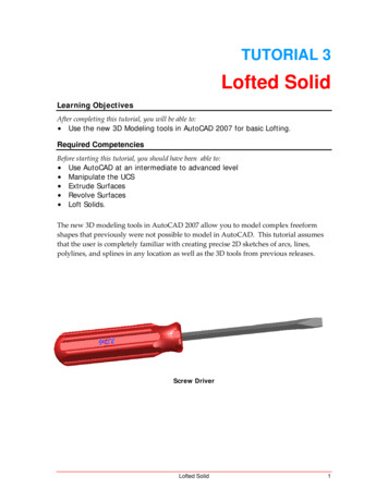
Schematic Library SymbolsBelow is an illustrated listing of the schematic symbols (along with theappropriate block name) supplied with AutoCAD Electrical. The schematicsymbols are illustrated here along with the appropriate block name.Push Buttons9
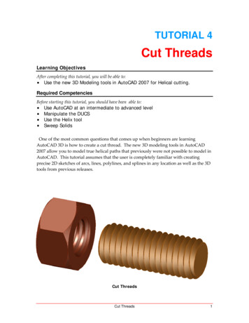
Illuminated Push Buttons10
Selector Switches11
Selector Switches (continued)12
Illuminated Selector Switches13
Limit SwitchesPressure SwitchesTemperature Switches14
Flow SwitchesLevel SwitchesProximity Switches15
Foot SwitchesPull Cord SwitchesAnti-Plugging Switches16
Toggle Switches17
Photo EyesPower Distribution Blocks18
Timers19
Relays20
Wire Markers21
Terminals22
Connectors - Wire Number Change23
Connectors - Wire Number Change (continued)24
Connectors - No Wire Number Change25
Connectors - No Wire Number Change(continued)26
Standard Pilot Lights27
Press to Test Pilot LightsNeon Pilot Lights28
Master Test Pilot Lights29
Miscellaneous30
Electronics31
ReceptaclesGeneric Boxes32
Stand-Alone Cross ReferenceWire Arrows - Reference Only33
FusesDisconnect Switches34
Circuit Breakers35
Motor ControlCapacitors36
TransformersSolenoids37
Instruments38
AutoCAD Electrical expects this symbol name to be “WDDOT.dwg.” Wire Number Symbols An AutoCAD Electrical wire number is a block insert consisting of a single wire number attribute. The origin of the block insert lies on its wire with the wire number attribute floati ng above, below, or off to the side of the block’s insertion point. ExamplesFile Size: 234KBPage Count: 38Adding a multiple catalog attribute value (user1) to a symbol .Dec 31, 2020Network symbols for AutoCAD Electrical? AutoCAD Electrical Libraries Catalogues Overview of symbol naming conventions